
DEFINITIONS - SAFETY GUIDELINES
indicates an imminently hazardous situation which, if not
avoided, will result in death or serious injury.
indicates a potentially hazardous situation which, if not avoided,
could result in death or serious injury.
indicates a potentially haz ard ous situation which, if not avoided,
may result in minor or mod er ate injury.
NOTICE
used without the safety alert symbol indicates potentially
hazardous situation which, if not avoided, may result in property damage.
To reduce the risk of injury, read the instruction manual.
GENERAL POWER TOOL SAFETY WARNINGS
Read all safety warnings and all instructions Failure to follow the
warnings and instructions may result in electric shock, fire and/or serious
injury.
SAVE ALL WARNINGS AND INSTRUCTIONS
FOR FUTURE REFERENCE
The term “power tool” in the warnings refers to your mains-operated (corded) power tool or battery-
operated (cordless) power tool.
1) WORK AREA SAFETY
a) Keep work area clean and well lit. Cluttered or dark areas invite accidents.
b) Do not operate power tools in explosive atmospheres, such as in the presence of
flammable liquids, gases or dust. Power tools create sparks which may ignite the dust or
fumes.
c) Keep children and bystanders away while operating a power tool. Distractions can
cause you to lose control.
2) ELECTRICAL SAFETY
a) Power tool plugs must match the outlet. Never modify the plug in any way. Do not
use any adapter plugs with earthed (grounded) power tools. Unmodified plugs and
matching outlets will reduce risk of electric shock.
b) Avoid body contact with earthed or grounded surfaces such as pipes, radiators,
ranges and refrigerators. There is an increased risk of electric shock if your body is earthed
or grounded.
c) Do not expose power tools to rain or wet conditions. Water entering a power tool will
increase the risk of electric shock.
d) Do not abuse the cord. Never use the cord for carrying, pulling or unplugging the
power tool. Keep cord away from heat, oil, sharp edges or moving parts. Damaged
or entangled cords increase the risk of electric shock.
e) When operating a power tool outdoors, use an extension cord suitable for outdoor
use. Use of a cord suitable for outdoor use reduces the risk of electric shock.
f) If operating a power tool in a damp location is unavoidable, use a ground fault circuit
interrupter (GFCI) protected supply. Use of a GFCI reduces the risk of electric shock.
3) PERSONAL SAFETY
a) Stay alert, watch what you are doing and use common sense when operating a
power tool. Do not use a power tool while you are tired or under the influence of
drugs, alcohol or medication. A moment of inattention while operating power tools may
result in serious personal injury.
b) Use personal protective equipment. Always wear eye protection. Protective equipment
such as dust mask, non-skid safety shoes, hard hat, or hearing protection used for
appropriate conditions will reduce personal injuries.
c) Prevent unintentional starting. Ensure the switch is in the off position before
connecting to power source and/or battery pack, picking up or carrying the tool.
Carrying power tools with your finger on the switch or energizing power tools that have the
switch on invites accidents.
d) Remove any adjusting key or wrench before turning the power tool on. A wrench or
a key left attached to a rotating part of the power tool may result in personal injury.
e) Do not overreach. Keep proper footing and balance at all times. This enables better
control of the power tool in unexpected situations.
f) Dress properly. Do not wear loose clothing or jewelry. Keep your hair, clothing and
gloves away from moving parts. Loose clothes, jewelry or long hair can be caught in
moving parts.
g) If devices are provided for the connection of dust extraction and collection facilities,
ensure these are connected and properly used. Use of dust collection can reduce dust-
related hazards.
4) POWER TOOL USE AND CARE
a) Do not force the power tool. Use the correct power tool for your application. The
correct power tool will do the job better and safer at the rate for which it was designed.
b) Do not use the power tool if the switch does not turn it on and off. Any power tool that
cannot be controlled with the switch is dangerous and must be repaired.
c) Disconnect the plug from the power source and/or the battery pack from the power
tool before making any adjustments, changing accessories, or storing power tools.
Such preventive safety measures reduce the risk of starting the power tool accidentally.
d) Store idle power tools out of the reach of children and do not allow persons
unfamiliar with the power tool or these instructions to operate the power tool. Power
tools are dangerous in the hands of untrained users.
e) Maintain power tools. Check for misalignment or binding of moving parts, breakage
of parts and any other condition that may affect the power tool’s operation. If
damaged, have the power tool repaired before use. Many accidents are caused by
poorly maintained power tools.
f) Keep cutting tools sharp and clean. Properly maintained cutting tools with sharp cutting
edges are less likely to bind and are easier to control.
g)
Use the power tool, accessories and tool bits, etc. in accordance with these
instructions, taking into account the working conditions and the work to be
performed. Use of the power tool for operations different from those intended could result in
a hazardous situation.
5) SERVICE
a) Have your power tool serviced by a qualified repair person using only identical
replacement parts. This will ensure that the safety of the power tool is maintained.
ADDITIONAL SPECIFIC SAFETY RULES
• Hold power tools by insulated gripping surfaces, because the cutter may contact its
own cord. Cutting a “live” wire will make exposed metal parts of the tool “live” and shock
the operator.
• Use clamps or another practical way to secure and support the workpiece to a stable
platform. Holding the work by your hand or against the body leaves it unstable and may
lead to loss of control.
• DO NOT cut metal.
• Keep handles and gripping surfaces dry, clean, and free from oil and grease. This will
enable better control of the tool.
• Maintain firm grip with both hands on router to resist starting torque.
• Keep hands away from cutting area. Never reach under the workpiece for any reason.
Keep the router base firmly in contact with the workpiece when cutting. These precautions will
reduce the risk of personal injury.
• Never run the motor unit when it is not inserted in one of the router bases. The motor
is not designed to be handheld.
• Keep cutting pressure constant. Do not overload motor.
• Check to see that the cord will not snag or impede the routing operation.
• Use sharp cutters. Dull cutters may cause the router to swerve or stall under pressure.
• Be sure that the motor has stopped completely before you lay the router down. If the
cutter head is still spinning when the tool is laid down, it could cause injury or damage.
• Be sure that the router bit is clear of the workpiece before starting the motor. If the bit
is in contact with the workpiece when the motor starts it could make the router jump, causing
damage or injury.
• ALWAYS disconnect tool from power source before making adjustments or changing
bits.
• Keep hands clear of bit when motor is running to prevent personal injury.
• Never touch the bit immediately after use. It may be extremely hot.
• Provide clearance under workpiece for router bit when through-cutting.
• Tighten collet nut securely to prevent the bit from slipping.
• Never tighten collet nut without a bit.
• Do not use router bits with a diameter in excess of 1-3/8" (34.9mm) in this tool.
• Always use cutters with a shank diameter of 1/4" (6.4 mm) which corresponds to the size of the
collet in your tool.
• Always follow the bit manufacturer's speed recommendations as some bit designs
require specific speeds for safety or performance. If you are unsure of the proper speed
or are experiencing any type of problem, contact the bit manufacturer.
• Not recommended for use in a router table.
• Avoid climb-cutting (cutting in direction opposite that shown in Figure 12).
Climb-cutting increases the chance for loss of control resulting in possible injury.
When climb-cutting is required (backing around a corner), exercise extreme caution to maintain
control of router. Make smaller cuts and remove minimal material with each pass.
• An extension cord must have adequate wire size (AWG or American Wire Gauge) for
safety. The smaller the gauge number of the wire, the greater the capacity of the cable, that is
16 gauge has more capacity than 18 gauge. An undersized cord will cause a drop in line voltage
resulting in loss of power and overheating. When using more than one extension to make up
the total length, be sure each individual extension contains at least the minimum wire size. The
following table shows the correct size to use depending on cord length and nameplate ampere
rating. If in doubt, use the next heavier gauge. The smaller the gauge number, the heavier the
cord.
Minimum Gauge for Cord Sets
Ampere Rating
Volts Total Length of Cord in Feet (meters)
120V 25 (7.6) 50 (15.2) 100 (30.5) 150 (45.7)
240V 50 (15.2) 100 (30.5) 200 (61.0) 300 (91.4)
More
Than
Not More
Than
AWG
0 6 18 16 16 14
610 18161412
10 12 16 16 14 12
12 16 14 12 Not Recommended
ALWAYS use safety glasses. Everyday eyeglasses are NOT safety glasses.
Also use face or dust mask if cutting operation is dusty. ALWAYS WEAR CERTIFIED SAFETY
EQUIPMENT:
• ANSI Z87.1 eye protection (CAN/CSA Z94.3),
• ANSI S12.6 (S3.19) hearing protection,
• NIOSH/OSHA/MSHA respiratory protection.
Some dust created by power sanding, sawing, grinding, drilling, and other
construction activities contains chemicals known to the State of California to cause cancer, birth
defects or other reproductive harm. Some examples of these chemicals are:
• lead from lead-based paints,
• crystalline silica from bricks and cement and other masonry products, and
• arsenic and chromium from chemically-treated lumber.
Your risk from these exposures varies, depending on how often you do this type of work. To reduce
your exposure to these chemicals: work in a well ventilated area, and work with approved safety
equipment, such as those dust masks that are specially designed to filter out microscopic particles.
• Avoid prolonged contact with dust from power sanding, sawing, grinding, drilling, and
other construction activities. Wear protective clothing and wash exposed areas with
soap and water. Allowing dust to get into your mouth, eyes, or lay on the skin may promote
absorption of harmful chemicals.
Use of this tool can generate and/or disburse dust, which may cause
serious and permanent respiratory or other injury. Always use NIOSH/OSHA approved
respiratory protection appropriate for the dust exposure. Direct particles away from face
and body.
Always wear proper personal hearing protection that conforms to ANSI
S12.6 (S3.19) during use. Under some conditions and duration of use, noise from this product
may contribute to hearing loss.
• The label on your tool may include the following symbols. The symbols and their definitions are
as follows:
V .....................volts A .........................amperes
Hz ................... hertz W ........................watts
min .................minutes or AC .............alternating current
or DC .....direct current or AC/DC......alternating or direct current
...................Class I Construction
n
o .......................no load speed
.......................
(grounded) n .........................rated speed
................... Class II Construction .......................earthing terminal
(double insulated)
........................safety alert symbol
…/min ............per minute BPM ...................beats per minute
IPM .................impacts per minute RPM ...................revolutions per minute
SPM ...............strokes per minute sfpm ...................surface feet per minute
OPM ................orbits per minute
SAVE THESE INSTRUCTIONS
MOTOR
Be sure your power supply agrees with nameplate marking. 120 Volts AC means your tool will
operate on alternating current. As little as 10% lower voltage can cause loss of power and can
result in overheating. All PORTER-CABLE tools are factory-tested; if this tool does not operate,
check the power supply.
To reduce the risk of injury, turn unit off and disconnect it from power
source before installing and removing accessories, before adjusting or when making
repairs.
An accidental start-up can cause injury.
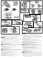
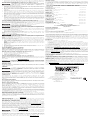
COMPONENTS (FIG. 1–11)
A. Quick release tabs R. Centering tool
B. Depth adjustment ring S. Collet nut
C. On(l)/off (o) switch T. Vacuum attachment (fixed base)
D. Spindle lock button U. Screws (vacuum attachment)
E. Guide pin groove V. Edge guide slot (plunge base)
F. Micro adjustment scale W. Router bit
G. Locking lever X. Motor unit
H. Edge guide slot (fixed base) Y. Motor stop
I. Subbase (sold separately) Z. Thumb screw
J. Vacuum attachment AA. Knurled knob
(For use with plunge base) BB. Depth adjustment scale
K. Holes for premium edge guide CC. Zero adjuster tab
(sold separately) DD. Sub-base screws
L. Turret stop EE. Edge guide screws
M. Depth adjustment rod FF. Tab (vacuum attachment)
N. Plunge lock lever GG. Snap tab (vacuum attachment)
O. Edge guide HH. Plastic washer (vacuum attachment)
P. Guide pins II. Thumb screw (vacuum attachment)
Q. Locking lever adjustment screw
OPERATION
To reduce the risk of injury, turn unit off and disconnect it from power
source before installing and removing accessories, before adjusting or when making
repairs. An accidental start-up can cause injury.
NOTICE
Do not use router bits with a diameter in excess of 1-3/8" (34.9mm) in
this tool.
CONNECTING TO POWER SOURCE
Before connecting tool to power source, check to see that the switch is in
the "OFF" position. Also, check the power circuit to see that it is the same as that shown on
specification plate of the tool.
STARTING AND STOPPING THE MOTOR (FIG. 1)
Before starting the tool, clear the work area of all foreign objects. Also keep firm
grip on tool to resist starting torque.
To avoid personal injury and/or damage to finished work, always allow the power
unit to come to a COMPLETE STOP before putting the tool down.
To turn unit on, depress the side of the dust-protected switch (C) that reads “ON” and corresponds to
the symbol “I.” To turn the unit off, depress the side of the switch that reads “OFF” and corresponds
with the symbol “O.”
MOTOR QUICK RELEASE (FIG. 2)
To reduce the risk of injury, turn unit off and disconnect it from power
source before installing and removing accessories, before adjusting or when making
repairs. An accidental start-up can cause injury.
1. Open the locking lever (G) on the base.
2. Grasp the motor unit (X) with one hand, depressing both quick release tabs (A).
3. With the other hand, grasp the base and pull motor from the base.
BIT INSTALLATION AND REMOVAL (FIG. 3)
To reduce the risk of injury, turn unit off and disconnect it from power
source before installing and removing accessories, before adjusting or when making
repairs. An accidental start-up can cause injury.
TO INSTALL THE BIT
1. Remove the motor unit from the base unit, see Motor Quick Release (if needed).
2. Clean and insert the round shank of the desired router bit into the loosened collet as far as it
will go and then pull it out about 1/16" (1.6 mm).
Instruction manual
Manuel d'instructions
Manual de'instrucciones
450
Part No. N336759 FEB14 Copyright © 2010, 2014 PORTER-CABLE
www.portercable.com
INSTRUCTIVO DE OPERACIÓN, CENTROS
DE SERVICIO Y PÓLIZA DE GARANTÍA.
LÉASE ESTE INSTRUCTIVO
ANTES DE USAR EL PRODUCTO.
COMPACT ROUTER
TOUPIE COMPACTE
REBAJADORA
COMPACTA
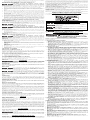
The following are PORTER-CABLE trademarks for one or more power tools and accessories: a gray and black color
scheme; a
“four point star” design; and three contrasting/outlined longitudinal stripes.

MOTOR
BLOC MOTEUR
UNIDAD DEL MOTOR
FIG. 1
FIXED BASE - BASE FIXE - BASE FIJA
G
I
F
K
L
M
N
PLUNGE BASE
BASE PLONGEANTE
BASE PARA PENETRACIÓN
Y
A
D
C
B
E
S
FIG. 2
A
P
E
G
FIG. 3
D
S
FIG. 7
O
H
EE
X
FIG. 5BFIG. 5A
DD
DD
R
FIG. 9
FF
GG
II
HH
J
P
B
V
E
3. Depress the spindle lock button (D) to hold the spindle shaft in place while turning the collet
nut (S) clockwise with the wrench provided. NOTE: The unit is equipped with multiple spindle
lock detents allowing an optional "manual ratchet" method of tightening the bit.
To tighten with the "manual ratchet" method:
a. Without removing the wrench from the collet nut (S), release pressure on the spindle lock
button (D).
b. With the wrench still on the collet nut (S), reverse the tightening direction to reset the
wrench position.
c. Depress the spindle lock button (D) again and turn the wrench clockwise.
d. Repeat the procedure until the collet nut (S) reaches desired tightness.
NOTICE
Avoid possible damage to the collet. Never tighten the collet without a bit.
TO REMOVE THE BIT
1. Remove the motor unit from the base unit, see Motor Quick Release.
2. Depress the spindle lock button (D) to hold the spindle shaft in place while turning the collet
nut (S) counterclockwise with the wrench provided.
To loosen using the "manual ratchet" method:
a. Without removing the wrench from the collet nut (S), release pressure on the spindle lock
button (D).
b. With the wrench still on the collet nut (S), reverse the loosening direction to reset the
wrench position.
c. Depress the spindle lock button (D) again and turn the wrench counterclockwise.
d. Repeat the procedure until the collet nut (S) is loose and the bit can be removed.
COLLETS
NOTE: Never tighten the collet without first installing a router bit in it. Tightening an empty collet,
even by hand, can damage the collet.
To change collet sizes, unscrew the collet assembly as described above. Install the desired collet
by reversing the procedure. The collet and the collet nut are connected. Do not attempt to remove
the collet from the collet nut.
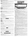
LOCKING LEVER ADJUSTMENT (FIG. 4)
To reduce the risk of injury, turn unit off and disconnect it from power
source before installing and removing accessories, before adjusting or when making
repairs. An accidental start-up can cause injury.
Excessive force should not be used to clamp the locking lever. Using excessive force may damage
the base.
When the locking lever is clamped the motor should not move in the base.
Adjustment is needed if the locking lever will not clamp without excessive force or if the motor
moves in the base after clamping.
To adjust the locking lever’s clamping force:
1. Open the locking lever (G).
2. Using a hex wrench turn locking lever adjustment screw (Q) in small increments.
Turning the screw clockwise tightens the lever, while turning the screw counterclockwise
loosens the lever.
CENTERING THE SUBBASE (FIG. 5)
To reduce the risk of injury, turn unit off and disconnect it from power
source before installing and removing accessories, before adjusting or when making
repairs. An accidental start-up can cause injury.
If you need to adjust, change, or replace the subbase, a centering tool (R) is recommended, refer
to Accessories. The centering tool consists of a cone and a pin.
To adjust the subbase:
1. Loosen but do not remove the subbase screws (DD) so the subbase moves freely.
2. Insert the pin into the collet and tighten the collet nut.
3. Insert the motor into the base and clamp the locking lever on the base.
4. Place the cone on the pin (Fig. 5A) and lightly press down on the cone until it stops as shown
in Figure 5B. This will center the subbase.
5. While holding down on the cone, tighten the subbase screws.
USING TEMPLATE GUIDES
The round subbase will accept universal template guides. Recommended accessories for use with
your tool are available at extra cost from your local dealer or authorized service center.
NOTE: The D-shape subbase does not accommodate template guides and is designed to
accommodate bits up to 1-3/8" (34.9mm) in diameter.
To use Template Guides
1. Center the subbase. See Centering The Subbase.
2. Install template guide (available as an accessory) on the subbase and tighten securely.
FIG. 6
G
B
F
B
F
FIG. 8
T
U
FIG. 10
1
4
3
2
FIG. 12
L
W
FIG. 11
N
AA
CC
Z
BB
M
ADJUSTING THE DEPTH OF CUT (FIG. 6)
To reduce the risk of injury, turn unit off and disconnect it from power
source before installing and removing accessories, before adjusting or when making
repairs. An accidental start-up can cause injury
1. Select and install the desired bit. See Bit Installation and Removal.
2. Assemble base to motor, ensuring base is attached to the depth adjustment ring. Place router
on the work piece.
3. Open the locking lever (G) and turn the depth adjustment ring (B) until the bit just touches the
work piece. Turning the ring clockwise raises the cutting head while turning it counterclockwise
lowers the cutting head.
4. Turn the micro adjustable scale (F) clockwise until the 0 on the scale lines up with the pointer
on the bottom of the depth adjustment ring.
5. Turn the depth adjustment ring until the pointer lines up with desired depth of cut marking
on the micro adjustable scale. NOTE: Each mark on the adjustable scale represents a depth
change of 1/64" or .015" (0.4 mm) and one full (360º) turn of the ring changes the depth 0.5"
(12.7mm).
6. Close the locking lever (G) to lock the base.
USING AN EDGE GUIDE (FIG. 7, 9)
An edge guide (model 45006) is available from your local retailer or service center at extra cost.
1. Remove the motor unit from the base unit, see Motor Quick Release.
2. Remove flat head screws (EE) from storage holes on edge guide.
3. Slide edge guide (O) into edge guide slot (H) on side of fixed base or (V) on side of plunge
base. Insert the two flat head screws through the appropriate holes in the sub base to secure
the edge guide. Tighten hardware.
4. Follow all instructions included with the edge guide.
NOTE: To remove the edge guide, reverse the above procedure. After removing edge guide always
replace the two flat head screws into the storage holes on the edge guide to prevent loss.
USING A PREMIUM EDGE GUIDE (PLUNGE BASE ONLY)
A Premium Edge Guide is available from your local retailer or service center at extra cost. Follow
the assembly instructions included with the edge guide.
VACUUM ATTACHMENT (FIXED BASE ONLY, FIG. 8)
To reduce the risk of injury, turn unit off and disconnect it from power
source before installing and removing accessories, before adjusting or when making
repairs. An accidental start-up can cause injury.
To connect the router to a vacuum cleaner for dust collection:
1. Remove the motor unit from the base unit, see Motor Quick Release.
2. Attach vacuum attachment accessory (T) to the base as shown. Tighten thumb screws (U)
securely by hand.
3. Attach hose adapter to vacuum attachment accessory.
4. When using vacuum attachment, be aware of the placement of the vacuum cleaner. Be sure
that the vacuum cleaner is stable and that its hose will not interfere with the work.
VACUUM ATTACHMENT (PLUNGE BASE ONLY, FIG. 9)
1. Remove the motor unit from the plunge base, see Motor Quick Release.
2. Slide tab (FF, inset) on vacuum attachment (J) into slot in plunge base and snap tab (GG, inset)
into hole in plunge base.
3. Secure to base with supplied plastic washer (HH) and thumb screw (II). Tighten thumb screw
securely by hand.
4 Attach hose adaptor to vacuum attachment.
5. When using vacuum attachment, be aware of the placement of the vacuum cleaner. Be sure
the vacuum cleaner is stable and its hose will not interfere with the work.
SET-UP: FIXED BASE (FIG. 1, 2, 10)
INSERTING THE MOTOR INTO THE FIXED BASE
To reduce the risk of injury, turn unit off and disconnect it from power
source before installing and removing accessories, before adjusting or when making
repairs. An accidental start-up can cause injury
1. Open the locking lever (G) on the base.
2. If the depth adjustment ring (B) is not on the motor, thread the depth adjustment ring (B) onto
the motor until the ring is about halfway between the top and bottom of the motor as shown.
Insert the motor into the base by aligning the groove on the motor (E) with the guide pins (P)
on the base. Slide the motor down until the depth adjustment ring snaps into place.
NOTE: Guide pin grooves (E) are located on either side of the motor so it can be positioned in
two orientations.
3. Adjust the depth of cut by turning the depth adjustment ring. See Adjusting the Depth of Cut.
4. Close the locking lever (G) when the desired depth is achieved. For information on setting the
cutting depth, see Adjusting the Depth of Cut.
ROUND SUBBASE
SEMELLE RONDE
SUB-BASE REDONDA
D-SHAPED SUBBASE
SEMELLE EN D
SUB-BASE EN FORMA DE D
TIGHTEN
SERRER
APRETAR
RESET
RÉINITIALISER
REPOSICIONAR
TIGHTEN
SERRER
APRETAR
Q
FIG. 4
G
X

SET-UP: PLUNGE BASE (FIG. 1, 10, 11)
INSERTING THE MOTOR INTO THE PLUNGE BASE
To reduce the risk of injury, turn unit off and disconnect it from power
source before installing and removing accessories, before adjusting or when making
repairs. An accidental start-up can cause injury
1. Remove the depth adjustment ring (B) from the motor. It is not used with the plunge base.
NOTE: Snap depth adjustment ring onto fixed base, when not in use, to prevent loss.
2. Insert the motor into the base by aligning the groove on the motor (E) with the guide pins (P)
on the base. Slide the motor down until the motor stops on the motor stop (Y).
3. Close the locking lever (G).
ADJUSTING THE PLUNGE ROUTING DEPTH (FIG. 11)
To reduce the risk of injury, turn unit off and disconnect it from power
source before installing and removing accessories, before adjusting or when making
repairs. An accidental start-up can cause injury
1. Unlock the plunge mechanism by pulling down the plunge lock lever (N). Plunge the router
down as far as it will go, allowing the bit (W) to just touch the workpiece.
2. Lock the plunge mechanism by releasing the plunge lock lever (N).
3. Loosen the depth adjustment rod (M) by turning the thumb screw (Z) counterclockwise.
4. Slide the depth adjustment rod (M) down so that it meets the lowest turret stop (L).
5. Slide the zero adjuster tab (CC) on the depth adjustment rod down so that the top of it meets
zero on the depth adjustment scale (BB).
6. Grasping the top, knurled section of the depth adjustment rod (M), slide it up so that the tab
(CC) aligns with the desired depth of cut on the depth adjustment scale (BB).
7. Tighten the thumb screw (Z) to hold the depth adjustment rod in place.
8. Keeping both hands on the handles, unlock the plunge mechanism by pulling the plunge
lock lever (N) down. The plunge mechanism and the motor will move up. When the router is
plunged, the depth adjustment rod will hit the turret stop, allowing the router to reach exactly
the desired depth.
USING THE ROTATING TURRET FOR STEPPED CUTS (FIG. 11)
If the depth of cut required is more than is acceptable in a single pass, rotate the turret so that depth
rod (M) lines up with taller turret stop initially. After each cut, rotate the turret so that the depth stop
lines up with shorter post until the final depth of cut is reached.
Do not change the turret stop while the router is running. This will place your
hands too near the cutter head.
FINE ADJUSTMENT OF ROUTING DEPTH (FIG. 11)
To reduce the risk of injury, turn unit off and disconnect it from power
source before installing and removing accessories, before adjusting or when making
repairs. An accidental start-up can cause injury
The knurled knob (AA) at the bottom end of the depth adjustment rod can be used to make minor
adjustments.
1. To decrease the cutting depth, rotate the knob clockwise (looking down from the top of the
router).
2. To increase the cutting depth, rotate the knob counterclockwise (looking down from the top of
the router).
NOTE: One complete rotation of the knob results in a change of about 5/128" or .04" (1 mm) in
depth.
CUTTING WITH THE PLUNGE BASE (FIG. 11)
To reduce the risk of injury, turn unit off and disconnect it from power
source before installing and removing accessories, before adjusting or when making
repairs. An accidental start-up can cause injury
NOTE: The depth of cut is locked in the plunge base's default state. The plunge lock requires user
actuation to enable the "release to lock" plunge mechanism.
1. Depress the plunge lock lever (N) and plunge the router down until the bit reaches the set
depth.
2. Release the plunge lock lever (N) when desired depth is reached.
NOTE: Releasing the plunge lock lever automatically locks the motor in place.
NOTE: If additional resistence is needed use the hand to depress the plunge lock lever.
3. Perform the cut.
4. Depressing the plunge lock lever will disable the locking mechanism allowing the router bit to
disengage from the work piece.
5. Turn the router off.
OPERATION: ALL BASES
DIRECTION OF FEED (FIG. 12)
The direction of feed is very important when routing and can make the difference between a
successful job and a ruined project. The figures show the proper direction of feed for some typical
cuts. A general rule to follow is to move the router in a counterclockwise direction on an outside cut
and a clockwise direction on an inside cut.
Shape the outside edge of a piece of stock by following these steps:
1. Shape the end grain, left to right
2. Shape the straight grain side moving left to right
3. Cut the other end grain side
4. Finish the remaining straight grain edge
SOFT START FEATURE (ALL MODELS)
The Compact Routers are equipped with electronics to provide a soft start feature that minimizes
the start up torque of the motor.
NOTE: Make several light passes instead of one heavy pass for better quality work.
MAINTENANCE
To reduce the risk of injury, turn unit off and disconnect it from power
source before installing and removing accessories, before adjusting or when making
repairs.
An accidental start-up can cause injury.
REPAIRS
For assistance with your tool, visit our website at www.portercable.com for a list of service centers,
or call the PORTER-CABLE Customer Care Center at (888) 848-5175.
CLEANING
Periodically blowing dust and chips out of the motor housing using clean, dry
compressed air is a suggested maintenance procedure. To reduce the risk of serious personal
injury, ALWAYS wear ANSI Z87.1 safety glasses while using compressed air.
When cleaning, use only mild soap and a damp cloth on plastic parts. Many
household cleaners contain chemicals which could seriously damage plastic. Also, do not use
gasoline, turpentine, lacquer or paint thinner, dry cleaning fluids or similar products which may
seriously damage plastic parts. NEVER let any liquid get inside the tool; NEVER immerse any part
of the tool into a liquid.
LUBRICATION
This tool has been lubricated with a sufficient amount of high grade lubricant for the life of the unit
under normal operating conditions. No further lubrication is necessary. However, it is recommended
that, once a year, you take or send the tool to a PORTER-CABLE service center for a thorough
cleaning and inspection.
FAILURE TO START
Should your tool fail to start, check to make sure the prongs on the cord plug are making good
contact in the outlet. Also, check for blown fuses or open circuit breakers in the line.
BRUSH INSPECTION
For your continued safety and electrical protection, brush inspection and replacement on this tool should
ONLY be performed by a PORTER-CABLE factory service center or porter-cable authorized warranty
service center.
At approximately 100 hours of use, take or send your tool to your nearest PORTER-CABLE Factory
Service center or PORTER-CABLE Authorized Warranty Service Center to be thoroughly cleaned and
inspected. Have worn parts replaced and lubricated with fresh lubricant. Have new brushes installed,
and test the tool for performance.
Any loss of power before the above maintenance check may indicate the need for immediate servicing
of your tool. DO NOT CONTINUE TO OPERATE TOOL UNDER THIS CONDITION. If proper operating
voltage is present, return your tool to the service station for immediate service.
WAXING MOTOR AND BASE
To maintain a smooth action when moving the motor unit in relation to the base, the outside of the
motor unit and the inside of the base can be waxed using any standard paste or liquid wax. Per the
manufacturers instructions, rub the wax onto the outside diameter of the motor unit and the inside
diameter of the base. Allow wax to dry and buff off residue with a soft cloth.
SERVICE
REPLACEMENT PARTS
Use only identical replacement parts. For a parts list or to order parts, visit our company’s service
website at servicenet.portercable.com. You can also order parts from your nearest PORTER-
CABLE Factory Service Center or PORTER-CABLE Authorized Warranty Service Center. Or, you
can call our Customer Care Center at (888) 848-5175.
SERVICE AND REPAIRS
All quality tools will eventually require servicing and/or replacement of parts. For information about
PORTER-CABLE, its factory service centers or authorized warranty service centers, visit our
website at www.portercable.com or call our Customer Care Center at (888) 848-5175. All repairs
made by our service centers are fully guaranteed against defective material and workmanship. We
cannot guarantee repairs made or attempted by others.
You can also write to us for information at PORTER-CABLE, 4825 Highway 45 North, Jackson,
Tennessee 38305 - Attention: Product Service. Be sure to include all of the information shown on
the nameplate of your tool (model number, type, serial number, etc.).
ACCESSORIES
A complete line of accessories is available from your PORTER-CABLE Factory Service
Center or a PORTER-CABLE Authorized Warranty Service Center. Please visit our Web Site
www.portercable.com for a catalog or for the name of your nearest supplier.
Since accessories other than those offered by PORTER-CABLE have not been
tested with this product, use of such accessories could be hazardous. For safest operation, only
PORTER-CABLE recommended accessories should be used with this product.
THREE YEAR LIMITED WARRANTY
PORTER-CABLE will repair, without charge, any defects due to faulty materials or workmanship for three
years from the date of purchase. This warranty does not cover part failure due to normal wear or tool
abuse. For further detail of warranty coverage and warranty repair information, visit www.portercable.com
or call (888) 848-5175. This warranty does not apply to accessories or damage caused where repairs
have been made or attempted by others. This warranty gives you specific legal rights and you may have
other rights which vary in certain states or provinces.
In addition to the warranty, PORTER-CABLE tools are covered by our:
1 YEAR FREE SERVICE: PORTER-CABLE will maintain the tool and replace worn parts caused by
normal use, for free, any time during the first year after purchase.
90 DAY MONEY BACK GUARANTEE: If you are not completely satisfied with the performance of your
PORTER-CABLE Power Tool, Laser, or Nailer for any reason, you can return it within 90 days from the
date of purchase with a receipt for a full refund – no questions asked.
LATIN AMERICA: This warranty does not apply to products sold in Latin America. For products sold
in Latin America, see country specific warranty information contained in the packaging, call the local
company or see website for warranty information.
To register your tool for warranty service visit our website at www.portercable.com.
WARNING LABEL REPLACEMENT
If your warning labels become illegible or are missing, call (888) 848-5175 for a free replacement.
MESURES DE SÉCURITÉ - DÉFINITIONS
indique une situation dangereuse imminente qui, si elle n’est pas
évitée, causera la mort ou des blessures graves.
indique une situation potentiellement dangereuse qui, si elle
n’est pas évitée, pourrait se solder par un décès ou des blessures graves.
indique une situation potentiellement dangereuse qui, si elle n’est
pas évitée pourrait se solder par des blessures mineures ou modérées.
indique une pratique ne posant aucun risque de dommages
corporels mais qui par contre, si rien n’est fait pour l’éviter, pourrait poser des
risques de dommages matériels.
Afin de réduire le risque de blessures, lire le mode d’emploi de l’outil.
AVERTISSEMENTS DE SÉCURITÉ GÉNÉRAUX
POUR LES OUTILS ÉLECTRIQUES
Lire tous les avertissements de sécurité et les
directives. Le non-respect des avertissements et des
directives pourrait se solder par un choc électrique, un
incendie et/ou une blessure grave.
CONSERVER TOUS LES AVERTISSEMENTS ET TOUTES LES
DIRECTIVES POUR UN USAGE ULTÉRIEUR
Le terme « outil électrique » cité dans les avertissements se rapporte à votre outil électrique à
alimentation sur secteur (avec fil) ou par piles (sans fil).
1) SÉCURITÉ DU LIEU DE TRAVAIL
a) Tenir l’aire de travail propre et bien éclairée. Les lieux encombrés ou sombres sont
propices aux accidents.
b) Ne pas faire fonctionner d’outils électriques dans un milieu déflagrant, tel qu’en
présence de liquides, de gaz ou de poussières inflammables. Les outils électriques
produisent des étincelles qui pourraient enflammer la poussière ou les vapeurs.
c) Éloigner les enfants et les personnes à proximité pendant l’utilisation d’un outil
électrique. Une distraction pourrait en faire perdre la maîtrise à l’utilisateur.
2) SÉCURITÉ EN MATIÈRE D’ÉLECTRICITÉ
a) Les fiches des outils électriques doivent correspondre à la prise. Ne jamais modifier
la fiche d’aucune façon. Ne jamais utiliser de fiche d’adaptation avec un outil
électrique mis à la terre. Le risque de choc électrique sera réduit par l’utilisation de fiches
non modifiées correspondant à la prise.
b) Éviter tout contact physique avec des surfaces mises à la terre comme des tuyaux,
des radiateurs, des cuisinières et des réfrigérateurs. Le risque de choc électrique est
plus élevé si votre corps est mis à la terre.
c) Ne pas exposer les outils électriques à la pluie ou à l’humidité. La pénétration de l’eau
dans un outil électrique augmente le risque de choc électrique.
d) Ne pas utiliser le cordon de façon abusive. Ne jamais utiliser le cordon pour
transporter, tirer ou débrancher un outil électrique. Tenir le cordon éloigné de
la chaleur, de l’huile, des bords tranchants et des pièces mobiles. Les cordons
endommagés ou enchevêtrés augmentent les risques de choc électrique.
e) Pour l’utilisation d’un outil électrique à l’extérieur, se servir d’une rallonge convenant
à cette application. L’utilisation d’une rallonge conçue pour l’extérieur réduira les risques de
choc électrique.
f) S’il est impossible d’éviter l’utilisation d’un outil électrique dans un endroit humide,
brancher l’outil dans une prise ou sur un circuit d’alimentation dotés d’un disjoncteur
de fuite à la terre (GFCI). L’utilisation de ce type de disjoncteur réduit les risques de choc
électrique.
3) SÉCURITÉ PERSONNELLE
a) Être vigilant, surveiller le travail effectué et faire preuve de jugement lorsqu’un outil
électrique est utilisé. Ne pas utiliser d’outil électrique en cas de fatigue ou sous
l’influence de drogues, d’alcool ou de médicaments. Un simple moment d’inattention
en utilisant un outil électrique peut entraîner des blessures corporelles graves.
b) Utiliser des équipements de protection individuelle. Toujours porter une protection
oculaire. L’utilisation d’équipements de protection comme un masque antipoussière, des
chaussures antidérapantes, un casque de sécurité ou des protecteurs auditifs lorsque la
situation le requiert réduira les risques de blessures corporelles.
c) Empêcher les démarrages intempestifs. S’assurer que l’interrupteur se trouve à la
position d’arrêt avant de relier l’outil à une source d’alimentation et/ou d’insérer un
bloc-piles, de ramasser ou de transporter l’outil. Transporter un outil électrique alors
que le doigt repose sur l’interrupteur ou brancher un outil électrique dont l’interrupteur est à
la position de marche risque de provoquer un accident.
d) Retirer toute clé de réglage ou clé avant de démarrer l’outil. Une clé ou une clé de
réglage attachée à une partie pivotante de l’outil électrique peut provoquer des blessures
corporelles.
e) Ne pas trop tendre les bras. Conserver son équilibre en tout temps. Cela permet de
mieux maîtriser l’outil électrique dans les situations imprévues.
f) S’habiller de manière appropriée. Ne pas porter de vêtements amples ni de bijoux.
Garder les cheveux, les vêtements et les gants à l’écart des pièces mobiles. Les
vêtements amples, les bijoux ou les cheveux longs risquent de rester coincés dans les pièces
mobiles.
g) Si des composants sont fournis pour le raccordement de dispositifs de dépoussiérage
et de ramassage, s’assurer que ceux-ci sont bien raccordés et utilisés. L’utilisation
d’un dispositif de dépoussiérage peut réduire les dangers engendrés par les poussières.
4) UTILISATION ET ENTRETIEN D’UN OUTIL ÉLECTRIQUE
a) Ne pas forcer un outil électrique. Utiliser l’outil électrique approprié à l’application.
L’outil électrique approprié effectuera un meilleur travail, de façon plus sûre et à la vitesse pour
laquelle il a été conçu.
b) Ne pas utiliser un outil électrique dont l’interrupteur est défectueux. Tout outil
électrique dont l’interrupteur est défectueux est dangereux et doit être réparé.
c) Débrancher la fiche de la source d’alimentation et/ou du bloc-piles de l’outil
électrique avant de faire tout réglage ou changement d’accessoire ou avant de
ranger l’outil. Ces mesures préventives réduisent les risques de démarrage accidentel de
l’outil électrique.
d) Ranger les outils électriques hors de la portée des enfants et ne permettre à aucune
personne n’étant pas familière avec un outil électrique ou son mode d’emploi
d’utiliser cet outil. Les outils électriques deviennent dangereux entre les mains d’utilisateurs
inexpérimentés.
e) Entretien des outils électriques. Vérifier si les pièces mobiles sont mal alignées ou
coincées, si des pièces sont brisées ou présentent toute autre condition susceptible
de nuire au bon fonctionnement de l’outil électrique. En cas de dommage, faire
réparer l’outil électrique avant toute nouvelle utilisation. Beaucoup d’accidents sont
causés par des outils électriques mal entretenus.
f) S’assurer que les outils de coupe sont aiguisés et propres. Les outils de coupe bien
entretenus et affûtés sont moins susceptibles de se coincer et sont plus faciles à maîtriser.
g) Utiliser l’outil électrique, les accessoires, les forets, etc. conformément aux
présentes directives en tenant compte des conditions de travail et du travail à
effectuer. L’utilisation d’un outil électrique pour toute opération autre que celle pour laquelle
il a été conçu est dangereuse.
5) RÉPARATION
a) Faire réparer l’outil électrique par un réparateur professionnel en n’utilisant que des
pièces de rechange identiques. Cela permettra de maintenir une utilisation sécuritaire de
l’outil électrique.
RÈGLES PARTICULIÈRES DE SÉCURITÉ ADDITIONNELLES
• Tenir l’outil électrique par ses parties isolées car l’organe de coupe pourrait entrer
en contact avec son cordon. Couper un fil sous tension met les parties métalliques
exposées de l’outil électrique sous tension et électrocute l’utilisateur.
• Utiliser des serre-joints, ou tout autre moyen, pour fixer et immobiliser le matériau sur
une surface stable. Tenir la pièce avec la main ou contre son corps n’est pas suffisamment
stable et risque de provoquer une perte de maîtrise de l’outil.
• NE découper AUCUN métaux.
• Maintenir les poignées et les surfaces de prises propres et sèches, exemptes d’huile
ou de graisse. Cela permettra un meilleur contrôle de l’outil.
• Maintenir une prise ferme sur la toupie, à deux mains, pour résister à tout couple de
démarrage.
• Garder les mains éloignées des zones de coupe. Ne jamais passer les doigts sous
le matériau pour quelque raison que ce soit. Maintenir fermement la base de la toupie
tout contre la pièce pendant la coupe. Ces précautions réduiront tout risque de dommages
corporels.
• Ne pas faire tourner le bloc-moteur de la toupie tant que celle-ci ne sera pas insérée
dans l’une de ses bases. Le moteur n’a pas été conçu pour être tenu manuellement.
• Maintenir une pression de coupe constante. Ne pas surcharger le moteur.
• Vérifier que le cordon ne s’enchevêtrera pas dans la toupie ou n’entravera pas son
fonctionnement.
• Utiliser seulement des organes de coupe bien affûtés. Les organes de coupe émoussés
pourraient faire dévier la toupie ou la faire caler sous la contrainte.
• S’assurer que le moteur est à l’arrêt complet avant de poser la toupie. Le fait de
poser l’outil alors que l’organe de coupe continue de tourner pose des risques de dommages
corporels ou matériels.
• S’assurer que la fraise à défoncer ne touche pas la pièce à travailler avant de mettre
l’outil en marche. Le fait de la mettre en contact avec la pièce alors que le moteur démarre
pourra la faire rebondir et poser des risques de dommages matériels ou corporels.
• Déconnecter SYSTÉMATIQUEMENT l’outil du secteur avant de changer de fraise ou
d’effectuer tout réglage.
• Protéger les mains de la fraise lorsque le moteur tourne pour prévenir tout risque de
dommages corporels.
• Ne jamais toucher l’organe de coupe immédiatement après usage. Il pourrait être
extrêmement chaud.
• Laisser un espace sous la pièce pour que la fraise à défoncer puisse la traverser de
part en part.
Page is loading ...
Page is loading ...
Page is loading ...
Page is loading ...
-
 1
1
-
 2
2
-
 3
3
-
 4
4
-
 5
5
-
 6
6
-
 7
7


Ask a question and I''ll find the answer in the document
Finding information in a document is now easier with AI
in other languages
- français: Porter Cable 450 Manuel utilisateur
- español: Porter Cable 450 Manual de usuario
Related papers
-
Whirlpool 6931 User manual
-
Porter Cable 6931 User manual
-
-
-
Porter Cable 892 User manual
-
Porter Cable PCE6435 User manual
-
Porter Cable 693LRPK User manual
-
Porter Cable PN350 User manual
-
Porter Cable 892 User manual
-