Page is loading ...
EtherNAV
™
D7600 Series
Installation & Operation Instructions
managed ethernet
switches
GE Security

Manageable 8/9-Port Switch
PREFACE
This manual describes how to install and use the D7600 series EtherNav”
Manageable 8/9-Port 10/100/1000 Base-TX (100/1000 Base-FX) Ethernet Switch.
This switch integrates full wire speed switching technology with SNMP/RMON web-
based management functions. The D7600 series brings
a simple answer to today’s complicated networking environments.
To get the most out of this manual, you should have an understanding of Ethernet
networking concepts.
In this manual, you will find:
• Features on the Switch
• Illustrative LED functions
• Installation Instructions
• Management Configuration
• SNMP…
• Specifications
User’s Manual

Manageable 8/9-Port Switch
INSTALLATION & OPERATION MANUAL / IFS D7600
PREFACE
TABLE OF CONTENTS
PRODUCT OVERVIEW
Package Contents............................................................................................................................................ 1
Product Features............................................................................................................................ 1
Basic Features................................................................................................................ 1
Management Support................................................................................................ 2
Front Panel Display....................................................................................................................... 3
Physical Ports................................................................................................................................... 4
Basic Functions............................................................................................................................... 5
Unicast Switching......................................................................................................... 5
Multicast Switching...................................................................................................... 7
VLAN..................................................................................................................................................... 8
Broadcast Containment............................................................................................ 9
Multi-Based Multimedia Applications.................................................................. 9
Enhanced Security....................................................................................................... 9
VLAN Membership........................................................................................................ 9
VLAN Configuration..................................................................................................... 10
Intra-VLAN Communication..................................................................................... 10
Inter-VLAN Communication..................................................................................... 10
GVRP...................................................................................................................................................... 10
IGMP Snooping and IP Multicast Filtering........................................................................... 10
Switch Management..................................................................................................................... 11
INSTALLATION............................................................................................................................................. 12
Selecting A Site For The Switch................................................................................................ 12
Methods for Mounting the D7600............................................................................................. 12-15
Connecting To Power.................................................................................................................... 16
Power-On Self Test (POST)......................................................................................... 16
Connecting To Your Network.................................................................................................... 17
Cable Type & Length................................................................................................... 17
SWITCH MANAGEMENT...................................................................................................................... 18
Management Access Overview............................................................................................... 18-19
Administration Console................................................................................................................ 20
Direct Access................................................................................................................... 20
Web Management......................................................................................................................... 21
Netscape Navigator..................................................................................................... 21
Internet Explorer............................................................................................................ 21
User’s Manual

Manageable 8/9-Port Switch
INSTALLATION & OPERATION MANUAL / IFS D7600
SWITCH MANAGEMENT CONTINUED….
SNMP-Based Network Management................................................................................... 22
Protocols............................................................................................................................................. 22
Management Architecture........................................................................................................ 22
MENU-DRIVEN CONSOLE MANAGEMENT......................................................................... 23
Logging On To The Switch......................................................................................................... 23
At The Screen Prompt................................................................................................ 23
Switch Management Screen..................................................................................................... 24
Navigating Through The Console Interface...................................................... 25
Performing Basic Management Activities.......................................................................... 25-31
Alarm Configurations................................................................................................................... 32
To Perform Advanced Management Activities................................................ 33-55
Sending and Receiving Files...................................................................................................... 56-57
Logout................................................................................................................................................. 58
Save Settings.................................................................................................................................... 58
Restore Default Settings............................................................................................................. 58
Reboot................................................................................................................................................. 58
WEB-BASED BROWSER MANAGEMENT.............................................................................. 59
Logging On To The Switch......................................................................................................... 59
Understanding The Browser Interface................................................................................ 60
Performing File Activities............................................................................................................ 61
To Perform File Activities........................................................................................... 61
Performing Basic Setup Activities.......................................................................................... 62
To Perform Basic Setup Activities......................................................................... 62-66
Performing Advanced Setup Activities................................................................................. 67
To Perform Advanced Setup Activities................................................................ 67-79
SNMP & RMON MANAGEMENT.................................................................................................... 80
Overview............................................................................................................................................. 80
SNMP Agent and MIB (RFC 1213)............................................................................................ 80
RMON Groups Supported......................................................................................... 81
Bridge Groups Supported......................................................................................... 82
SPECIFICATIONS........................................................................................................................................ 83
APPENDIX A – CONNECTOR PINOUTS.................................................................................. 84
D7600 Front Panel Layouts........................................................................................................... 85-86
User’s Manual

Manageable 8/9-Port Switch
When you unpack the product package, you shall find the items listed below.
• D7600 EtherNav” Management Switch
• D7600 Quick Start Guide
• External Power Adapter
• CD ROM
Basic Features:
- Provides up to nine (10/100/1000TX and/or 100/1000FX combination) ports
- Multimode fiber using SC connectors up to 2 km; singlemode fiber using
SC connectors up to 15 km for 100FX, 10km for 1000FX
- Auto-negotiation for speed and duplicity on all TX ports
- Store-and-Forward mechanism
- Back-pressure and IEEE 802.3x compliant flow control
- Supports 4K MAC addresses
- Redundant power supply connections
- Optional TX or FX 1000Mbps aggregation port
- Optional contact closure for fiber loss alarm
Manageable 8/9-Port Switch
PRODUCT OVERVIEW
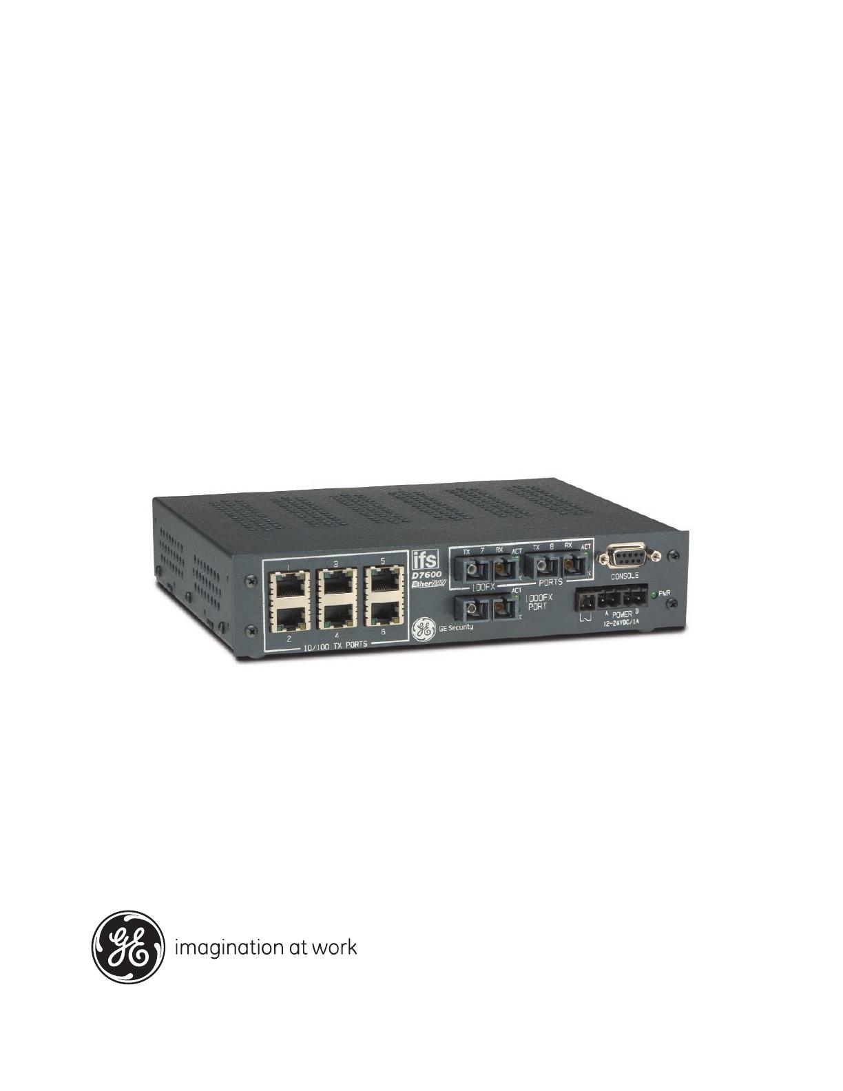
100FX Optical Ports
Console Port
10/100TX Electrical Ports
Front View (D7600-MM-E-CC shown)
10/100/1000TX Port
PACKAGE CONTENTS
PRODUCT FEATURES
User’s Manual 1
Fiber Loss Alarm
Power Ports

Manageable 8/9-Port Switch
PRODUCT FEATURES CONTINUED...
Management Support:
VLAN
- 802.1Q tagged VLAN (up to 64 VLANs)
- Quality of Service (QoS)
Link Aggregation
- Port-based Aggregation, up to four groups with a maximum
of four ports each group
- Load sharing based on source and destination MAC addresses
Port-Mirroring
- Port-mirroring provided through dedicated port, Port 1
Internet Working Protocols:
Bridging
- 802.1D Spanning Tree
- 802.1P/Q –GARP/GVRP
IP Multicast
- IP Multicast Packet Filtering
Network Management Methods:
- Console port access via RS-232 cable
- Telnet remote access
- SNMP Agent:
• MIB-2 (RFC1213)
• Bridge MIB (RFC1493)
• RMON MIB (RFC1757)-statistics, history, alarm & events
• VLAN MIB (802.1Q/RFC2674)
• Private MIB
- Web browser support based on HTTP server and CGI parser
- TFTP/Web software-upgrade capability
User’s Manual 2
User’s Manual 3
Manageable 8/9-Port Switch
FRONT PANEL DISPLAY
10/100TX Port Status
(D7600-MM-E-CC Shown)
Optical Status
10/100/1000TX Port Status
Power Indicator
1. Power Indicator
This LED comes on when the switch is properly connected to power.
2. Optical Status LED’s (FX)
The ACT LED’s come on when data is present.
(LED will flash at the rate data is transferred).
The LNK LED’s will be on for 100FX speed transmission.
3. 10/100/1000TX Port Status LED’s
The LED’s are located at each port, displaying status.
Please refer to the Table for more details.

User’s Manual 4
Manageable 8/9-Port Switch
LED State Indication
GREEN
YELLOW
Steady
A valid network connection established
Flashing
Data transfer
PHYSICAL PORTS
This EtherNav” managed switch provides up to nine (10/100/1000TX and/or 100/1000FX
combinations) ports:
CONNECTIVITY
- RJ-45 connectors
- SC connector on fiber ports
MODE SELECTION
- 10BaseT full-duplex mode
- 10BaseT half-duplex mode
- 100BaseTX full-duplex mode
- 100BaseTX half-duplex mode
- 100BaseFX full-duplex mode
- 100BaseFX half-duplex mode
- 1000BaseTX full-duplex mode
- 1000BaseTX half-duplex mode
- 1000BaseFX full-duplex mode
- 1000BaseFX half-duplex mode
- Auto-sensing mode except 100FX

Manageable 8/9-Port Switch
BASIC FUNCTIONS
In general, the D7600 is responsible for switching both VLAN tagged and untagged frames
from a receiving port to one or more transmitting ports. The switch performs multiple steps
during the switching process:
VLAN CLASSIFICATION
LEARNING
FILTERING
AGING
Below is additional information about tasks that the switch performs during unicast
and multicast switching.
User’s Manual 5
PLEASE NOTE:
I. Half-duplex mode uses back pressure flow control to prevent the receiving
buffer from being overrun by data from a source node.
II. Full-duplex mode uses 802.3x flow control standard to prevent fast data traffic
from overrunning slow data traffic.
III. Auto-sensing mode is in use after auto-negotiating with the other end of the link.
UNICAST SWITCHING
VLAN CLASSIFICATION
When the switch receives a frame, it classifies the frame in one of two ways:
- If the frame is untagged, the switch classifies the frame to an
associated VLAN.
- If the frame is tagged, the switch uses the tagged VLAN ID to identify the
broadcasting domain of the frame.

PLEASE NOTE:
I. Half-duplex mode uses back pressure flow control to prevent the receiving
buffer from being overrun by data from a source node.
II. Full-duplex mode uses 802.3x flow control standard to prevent fast data traffic
from overrunning slow data traffic.
III. Auto-sensing mode is in use after auto-negotiating with the other end of the link.
LEARNING
After VLAN classification, the switch checks the <source MAC address, VLAN> pair in the
switching database (SDB) to see whether the <source MAC address, VLAN> pair is known.
- If it is unknown, the switch inserts the <source MAC address, VLAN> into the SDB
and learns the <source MAC address, VLAN>.
- If it is known, the switch checks the <source MAC address, VLAN> for a mis
matched port ID. If the port ID associated with the <source MAC address, VLAN>
pair in the SDB is different than the receiving port, the switch modifies the port ID in
the SDB and modifies its management database (MDB) accordingly.
FILTERING
After learning the address, the switch checks:
- Whether the source port or destination port is in the forwarding state.
- Whether the source MAC address or destination MAC address is to be filtered.
- Whether the source port ID is the same as destination port ID.
If any of these conditions are met, the switch drops the receiving. Otherwise, it continues with
the forwarding process described below.
FORWARDING
During the forwarding process, the switch checks whether the <destination MAC address,
VLAN> pair is unknown.
- If it is unknown, the switch floods the receiving frame to all ports in the VLAN,
excluding the source port.
- If it is known, the switch forwards the receiving frame to the port associated
with the <destination MAC address, VLAN> pair. At the same time, the switch
ascertains the individual’s ports VLAN tagging and/or un-tagging configuration
and corresponding VLAN ID render the appropriate frame tagging when the frame
is ready to be transmitted.
Manageable 8/9-Port Switch
User’s Manual 6

User’s Manual 7
Manageable 8/9-Port Switch
MULTICAST SWITCHING
For multicast switching, the D7600 checks whether the received frame is a BPDU. If a BPDU
is received, the switch forwards the frame to the CPU for processing by the spanning tree
protocol. Otherwise, the D7600 performs the following processes:
VLAN CLASSIFICATION
Same as for unicast switching.
LEARNING
Same as for unicast switching.
FILTERING
After learning the address, the switch checks:
- Whether the source port or destination port is not in the following state.
- Whether the source MAC address or destination MAC address is to be filtered.
If any of these conditions are met, the switch drops the receiving. Otherwise, it
continues with the forwarding process described below.
FORWARDING
The D7600 floods the received multicast frame to all ports that are in the forwarding state
within the VLAN, excluding the source port. At the same time, the switch
ascertains the individual ports VLAN tagging/untagging configuration and
corresponding VLAN to render the appropriate frame tagging when the frame is
ready to be transmitted.
AGING
The switch performs the aging process for the <MAC addresses, VLAN> pair in
the switching database. Once a <MAC address, VLAN> pair is aged out, the SBD
is modified.
SPANNING TREE
The D7600 supports one Spanning Tree per bridged network.

User’s Manual 8
Manageable 8/9-Port Switch
VLAN
A virtual LAN (VLAN) is a network of computers or peripherals that behave as if they are
connected to the same wire, even though they may actually be physically located
in different locations of a LAN. VLANs are similar to a group of end stations, perhaps on
multiple physical LAN segments that are not inhibited by their physical location
and can communicate as if they were on a common LAN.
VLANs are configured through software rather than hardware, which makes the extremely
flexible. One of the biggest advantages of VLANs is that when a peripheral
is physically moved to another location, it can stay on the same VLAN without any
hardware reconfiguration.
Because VLANs are not limited by the hardware constraints that physically connect
traditional LAN segments to a network, they can define a network into various logical con-
figurations. For example, VLANs can define a network by function.
In this setting, a system integrator might create one VLAN for multimedia users
and another for email users. VLANs can also define a network by location or type of serv-
ice. For example, a location might have one VLAN for its cameras, another for it access
control, and another for its roadside signs.
VLANs can also be set up according to the organization structure within a company. For
example, the company president might have his/her own VLAN, the executive staff might
have a different VLAN, and the remaining employees might have yet another
different VLAN.
As these examples show, VLANs offer matchless flexibility. The following
sections describe how deploying VLANs can benefit system integrators and
reduce design costs.

BROADCAST CONTROL
In traditional networks, traffic broadcasts to all network devices, whether they are the intended
recipients or not. However, VLANs can be set up to contain only those devices that need to
communicate with each other. As a result, VLANs considerably reduce
network congestion. In addition, VLANs prevent broadcast storms from causing a
network from crashing due to volumes of traffic.
MULTICAST-BASED MULTIMEDIA APPLICATIONS
Multimedia applications, such as interactive training, video monitoring, and video/data trans-
missions, require large amounts of bandwidth. These applications are also extremely sensitive
to variable delays, which are inevitable on a shared Ethernet network. By
defining a VLAN based on the IP multicast address for all defined members on the
VLAN, adequate bandwidth will be available for these applications, providing true
multimedia Ethernet.
IMPROVED SECURITY
Because VLANs are independent, only the devices within the same VLAN can
communicate with each other. If a device in one VLAN wants to communicate with
a device in another VLAN, the traffic must go through a router.
VLAN MEMBERSHIP
VLAN implementation allows:
- Up to 64 VLANs in one switch.
- VLANs across multiple switches by using explicit or implicit tagging and the
GARP/GVRP protocol defined in IEEE802.1p and 802.1Q.
- An end station’s network interface card belongs to multiple VLANs.
-A switch port to be associated with multiple VLANs.
DEFINITIONS OF VLAN MEMBERSHIP
VLAN implementation allows VLAN membership to be defined based on ports.
Physical port numbers organizes port-based VLANs. For example, switch ports
1,2,4 and 6 can be grouped on VLAN, while server ports 3,5,7 and 8 can be on another VLAN.
Broadcasts from servers within each group would only go to the members of its own VLAN.
This ensures that broadcast storms cannot cause a network to crash due to
volumes of traffic.
VLAN MEMBERSHIP LEARNING
Port-based VLAN is defined using a static binding between a VLAN and its associated ports.
The switch’s forwarding decision is based on the destination MAC address and
its associated port ID. Therefore, to make valid forwarding and flooding decisions, the switch
learns the relationship of the MAC address to its related port…and thus to the VLAN…at runtime.
Manageable 8/9-Port Switch
User’s Manual 9

Manageable 8/9-Port Switch
User’s Manual 10
REMOTE VLAN MEMBERSHIP
Additionally to providing network management tools that allow network administrators to stat-
ically add and delete VLAN member ports, the switch also supports GVRP (GARP VLAN
Registration Protocol). GVRP allows for dynamic registration of VLAN port
members within switch and across multiple switches.
Other than supporting dynamic updating of registration entries in a switch, GVRP is
used to communicate VLAN registration information to other VLAN-aware switches,
so that a VLAN member can cover a wide span of switches on a network.
GVRP allows both VLAN-aware workstations and switches to issue and revoke VLAN member-
ships. VLAN-aware switches register a propagate VLAN membership to all
ports that belong to the active topology of the VLAN.
VLAN CONFIGURATION
The switch provides a Local/Remote Management Console Interface for VLAN
configuration and management. An SNMP-based VLAN MIB is also provided.
INTRA-VLAN COMMUNICATION
The switch supports intra-VLAN communication through hardware as described in
"Basic Functions" section.
INTER-VLAN COMMUNICATION
The switch supports Inter-VLAN communication using CPU-based routing software.
GVRP (GARP VLAN Registration Protocol)
IGMP SNOOPING AND IP MULTICAST FILTERING
In addition to network management tools that allow network administrators to statically add
and delete VLAN member ports, the routing switch supports GARP VLAN Registration Protocol
(GVRP). GVRP supports dynamic registration of VLAN port
members within a switch and across multiple switches.
In addition to dynamically updating registration entries with a switch, GVRP is used to commu-
nicate VLAN registration information to other VLAN-aware switches, so that
members of a VLAN can cover a wide span of switches on a network.
GVRP allows both VLAN-aware workstations and switches to issue and revoke VLAN member-
ships. VLAN-aware switches register and propagate VLAN membership to all ports that are
part of the active topology of the VLAN.
The Internet Group Management Protocol (IGMP) runs between hosts and their immediately
neighboring multicast routers. The protocol’s mechanisms allow a host to inform its local router
that it wants to receive transmissions addressed to a specific multicast group.
Routers periodically query the LAN to determine if known group members are still active.

User’s Manual 11
Manageable 8/9-Port Switch
IGMP Snooping & IP Multicast Filtering Continued...
If there is more than one router on the LAN performing IP multicasting, one of the routers is
elected ‘querier’ and assumes the reponsibility.
Based on the group membership information learned from the IGMP, a router can deter-
mine which (if any) multicast traffic needs to be forwarded to each of its ‘leaf’
sub-networks. Multicast routers use this information, along with a multicast routing
protocol, to support IP multicasting across the Internet.
Routing switches support IP Multicast Filtering by:
• Passively snooping on the IGMP Query and IGMP Report packets transferred
between IP Multicast Routers and IP Multicast host groups to learn about IP
Multicast group members, and
• Actively sending IGMP Query messages to solicit IP Multicast group members.
The purpose of IP multicast filtering is to optimize a switched network’s performance, so
multicast packets will only be forwarded to those ports containing multicast group hosts
members and routers instead of flooding to all ports in the subnet (VLAN).
Routing switches with IP multicast filtering/switching capability not only run passively mon-
itor IGMP Query and Report messages, DVMRP Probe messages, PIM, and MOSPF Hello
messages; they also actively send IGMP Query messages to learn locations of multicast
routers and member hosts in multicast groups within each VLAN.
Note, however, IGMP neither alters nor routes any IP multicast packets. Since IGMP
is not concerned with the delivery of IP multicast packets across sub-networks, an
external IP multicast router is needed if IP multicast packets have to be routed
across different sub-networks.
SWITCH MANAGEMENT
Administration Console Via RS-232 Console Port:
The switch provides an on board serial port, which allows the switch to be configured via a
directly connected terminal or a Telnet session.
Web-Based Browser Interface:
The switch also boasts a point-and-click browser-based interface that lets users access full
switch configuration and functionality from a Netscape or Internet Explorer browser.
External SNMP-Based Network Management:
The switch can also be configured via SNMP.
For more information on switch management, please refer to the "Switch Management" section.
User’s Manual
Manageable 8/9-Port Switch
INSTALLATION
This section gives step-by-step instructions about how to install
the EtherNav” D7600 switch:
Selecting a Site for the Switch
As with any electric device, you should place the switch where it will not be subjected to
temperatures, humidity, or electromagnetic interference above the rated specifications. The
site you select should meet the following requirements:
• The ambient temperature should be between –40 to 74 degrees Celsius.
• The relative humidity should be less than 95 percent, non-condensing.
• Surrounding electrical devices should not exceed the electromagnetic field
(RFC) standards for EIC 801-3, Level 2 (3V/M) field strength.
• Make sure that the switch receives adequate ventilation. Avoid blocking the
ventilation holes on all sides of the switch.
Methods for Mounting the D7600
Several mounting configurations are available for the variety of applications for which this
switch was designed. Each configuration is described as follows:
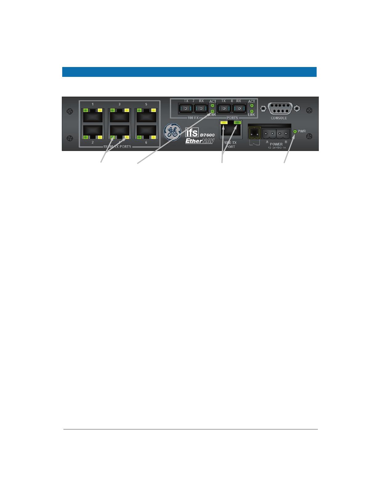
Wall Mounting (-W Option)
The brackets provided will require the removal and re-installation of the cover screws as
shown below.
Note: Insure that all screw are re-installed for adequate stability in mounting. 12
Bracket
(-W Option)
Cover Screws

Manageable 8/9-Port Switch
User’s Manual 13
DIN Rail Back Mounting (-DB Option)
The bracket provided will require the removal and re-installation of some cover screws as
shown below.
DIN Rail Side Mounting (-DS Option)
The bracket provided will require the removal and re-installation of one cover screw, the other
screws are provided with the bracket as shown below.
Bracket
(-DB Option)
Cover Screws
Note: Bracket is mounted on the Power
Supply Side (Right Side) of the switch.
Bracket
(-DS Option)
D7600 Unit
(10/100 Port Side)
Cover Screw
Provided Mounting
Screws
Manageable 8/9-Port Switch
User’s Manual 14
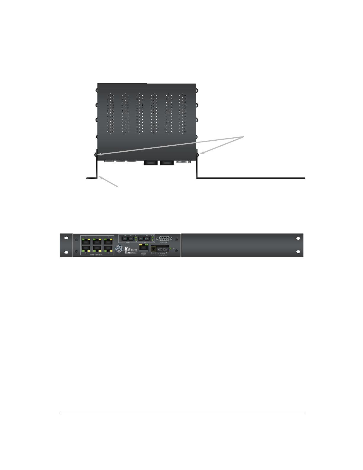
Rack Mounting Single Unit (-RS Option)
The brackets provided have screws included for proper mounting as shown below.
Note: All screws must be fastened and secured to insure adequate stability and strength.
Mounting Screws
4 Locations (Provided)
Brackets (-RS Option)
(Top View)
(Front View)
Manageable 8/9-Port Switch
User’s Manual 15
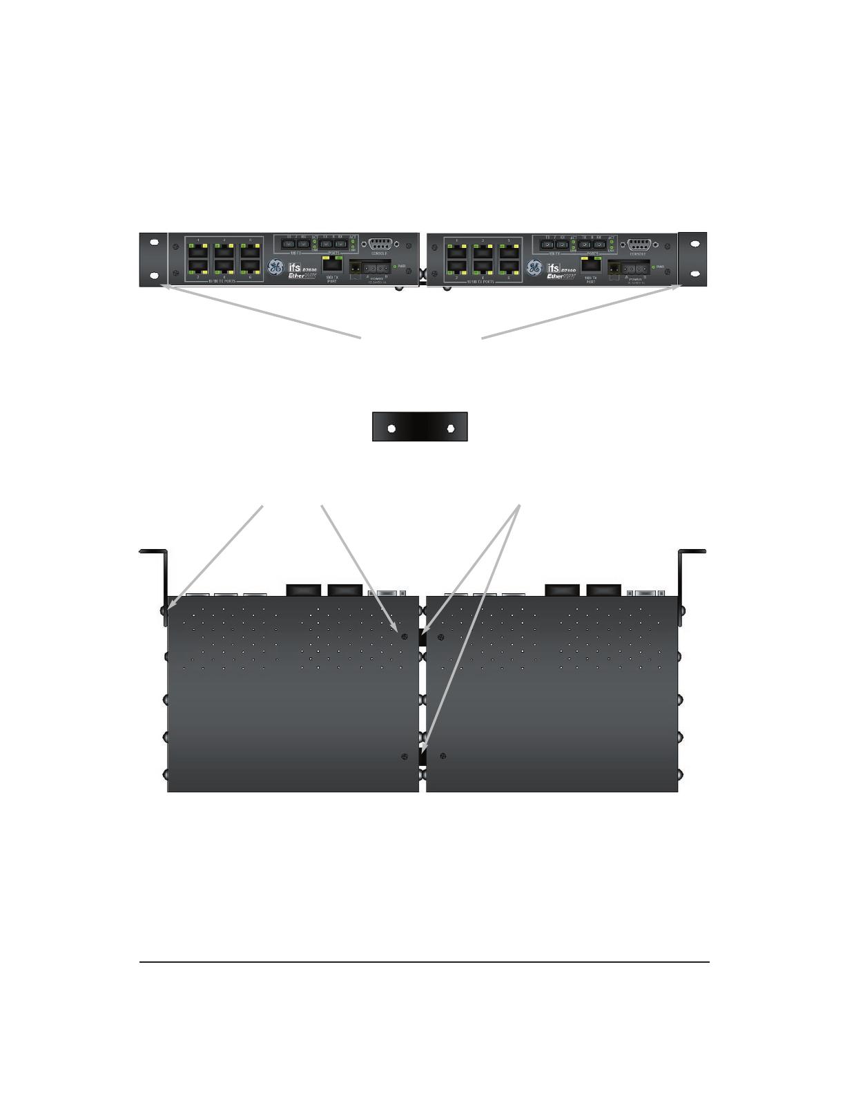
Rack Mounting Dual Units (-RD Option)
The brackets and braces provided have screws included for proper
mounting as shown below.
Brackets (2 Provided)
Mounting
Screws
Brace
Locations
(Front View)
Brace (2 Provided )
(Bottom View)
Manageable 8/9-Port Switch
User’s Manual 16
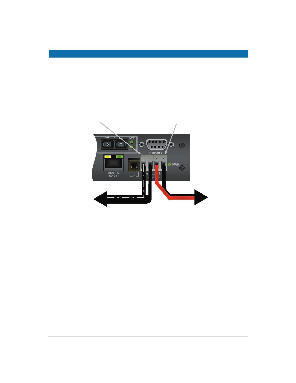
CONNECTING TO POWER
External Power
Step One: Wire the supplied AC power adapter to the “A” receptacle plug
at the front of the switch. — white stripe to pin 1 (+), black to pin 2 (-).
Step Two: Attach the plug into a standard AC outlet with the appropriate AC voltage.
Note: The secondary supply must be equal to or less than the potential of the primary supply.
To Primary Wall Supply
To Secondary Supply
Secondary “B” Power Connector
Primary “A” Power Connector
(D7600-MM-E-CC Shown))
Power On Self Test (POST)
The switch performs its Power-On Self Test (POST) when the power is applied to the switch.
During the POST, the switch CPU will:
• Perform a series of diagnostic procedures to make sure the
basic system is functioning properly
• Decompresses the main switching software runtime image from
the flash ROM into the DRAM area
/