
Frymaster, a member of the Commercial Food Equipment Service Association, recommends
using CFESA Certified Technicians.
24-Hour Service Hotline 1-800-551-8633
NOV 08
www.frymaster.com
E-mail: [email protected]
*8196203*
This manual is applicable to fryers manufactured beginning
May 2006 with serial
numbers beginning with 0604. For serial numbers between 0308 to 0604 refer to
manual 819-6004. For serial numbers prior to 0308, refer to manual 819-5184.
NAVY SURFACE SHIP ELECTRIC
FRYERS
Installation, Operation, Service, and Parts Manual
H14SC/H17SC/H22SC Single Fryers, FPH17SC Series Filtration System Fryers

NOTICE
IF, DURING THE WARRANTY PERIOD, THE CUSTOMER USES A PART FOR THIS ENODIS
EQUIPMENT OTHER THAN AN UNMODIFIED NEW OR RECYCLED PART PURCHASED
DIRECTLY FROM FRYMASTER DEAN, OR ANY OF ITS AUTHORIZED SERVICE CENTERS,
AND/OR THE PART BEING USED IS MODIFIED FROM ITS ORIGINAL CONFIGURATION, THIS
WARRANTY WILL BE VOID. FURTHER, FRYMASTER DEAN AND ITS AFFILIATES WILL NOT BE
LIABLE FOR ANY CLAIMS, DAMAGES OR EXPENSES INCURRED BY THE CUSTOMER WHICH
ARISE DIRECTLY OR INDIRECTLY, IN WHOLE OR IN PART, DUE TO THE INSTALLATION OF
ANY MODIFIED PART AND/OR PART RECEIVED FROM AN UNAUTHORIZED SERVICE CENTER.
DANGER
Copper wire suitable for at least 167°F (75°C) must be used for power connections.
DANGER
The electrical power supply for this appliance must be the same as indicated on the rating and
serial number plate located on the inside of the fryer door.
DANGER
This appliance must be connected to the voltage and phase as specified on the rating and serial
number plate located on the inside of the fryer door.
DANGER
All wiring connections for this appliance must be made in accordance with the wiring diagrams
furnished with the equipment. Wiring diagrams are located on the inside of the fryer door.
DANGER
Do not store or use gasoline or other flammable vapors and liquids in the vicinity of this or any
other appliance.
NOTICE
Drawings and photos used in this manual are intended to illustrate operational, cleaning and
technical procedures. They may differ slightly in appearance or placement between fryers but
functionality should remain the same. They may not conform to onsite management operational
procedures.
WARNING
Frymaster fryers equipped with legs are for permanent installations. Fryers fitted with legs
must be lifted during movement to avoid damage and possible bodily injury. For a moveable or
portable installation, Frymaster optional equipment casters must be used.
Questions? Call 1-800-551-8633 or email at [email protected]
DANGER
The front ledge of the fryer is not a step. Do not stand on the fryer. Serious injury can result
from slips or contact with the hot oil.
DANGER
All wiring connections for this appliance must be made in accordance with the wiring diagrams
furnished with the equipment. Wiring diagrams are located on the inside of the fryer door.
WARNING
This equipment is intended for indoor use only. Do not install or operate this equipment in
outdoor areas.

NOTICE
This appliance is intended for professional use only and is to be operated by qualified
personnel only. A Frymaster DEAN Factory Authorized Service Center (FASC) or other qualified
professional should perform installation, maintenance, and repairs. Installation, maintenance,
or repairs by unqualified personnel may void the manufacturer’s warranty.
NOTICE
This equipment must be installed in accordance with the appropriate national and local codes of
the country and/or region in which the appliance is installed.
NOTICE TO U.S. CUSTOMERS
This equipment is to be installed in compliance with the basic plumbing code of the Building
Officials and Code Administrators International, Inc. (BOCA) and the Food Service Sanitation
Manual of the U.S. Food and Drug Administration.
WARNING
No structural material on the fryer should be altered or removed to accommodate placement of
the fryer under a hood. Questions? Call the Frymaster Dean Service Hotline at 1-800-551-8633.
NOTICE TO OWNERS OF UNITS EQUIPPED WITH COMPUTERS
U.S.
This device complies with Part 15 of the FCC rules. Operation is subject to the following two
conditions: 1) This device may not cause harmful interference, and 2) This device must accept
any interference received, including interference that may cause undesired operation. While
this device is a verified Class A device, it has been shown to meet the Class B limits.
CANADA
This digital apparatus does not exceed the Class A or B limits for radio noise emissions as set
out by the ICES-003 standard of the Canadian Department of Communications.
Cet appareil numerique n’emet pas de bruits radioelectriques depassany les limites de classe A
et B prescrites dans la norme NMB-003 edictee par le Ministre des Communcations du Canada.
DANGER
Improper installation, adjustment, maintenance or service, and unauthorized alterations or
modifications can cause property damage, injury, or death. Read the installation, operating,
and service instructions thoroughly before installing or servicing this equipment.
DANGER
The crumb tray in fryers equipped with a filter system must be emptied into a fireproof container
at the end of frying operations each day. Some food particles can spontaneously combust if left
soaking in certain shortening material.
WARNING
Do not bang fry baskets or other utensils on the fryer’s joiner strip. The strip is present to seal
the joint between the frypots. Banging fry baskets on the strip to dislodge shortening will
distort the strip, adversely affecting its fit. It is designed for a tight fit and should only be
removed for cleaning.
WARNING
Never spray the fryer with water or use water jets to clean the fryer.

i
Navy Surface Ship Electric Fryers
Installation, Operation, Service, and Parts Manual
TABLE OF CONTENTS
Page
Chapter 1: Introduction
1-1
Chapter 2: Installation Instructions 2-1
Chapter 3: Operating Instructions 3-1
Chapter 4: Filtration Instructions 4-1
Chapter 5: Preventive Maintenance 5-1
Chapter 6: Operator Troubleshooting 6-1
Chapter 7: Service Procedures 7-1
Chapter 8: Parts List 8-1

1-1
NAVY SURFACE SHIP ELECTRIC FRYERS
CHAPTER 1: INTRODUCTION
1.1 General
Read the instructions in this manual thoroughly before attempting to operate this equipment. This
manual covers all configurations of Navy Surface Ship Electric Fryer models specifically configured
for use aboard surface ships of the U.S. Navy, including H14SC/H17SC/H22SC kW and FPH17SC
kW filtration system models. The fryers in this model family have most parts in common, and when
discussed as a group, will be referred to as “Navy Surface Ship Electric” fryers.
Although similar in appearance to the Footprint Pro family of Navy Electric fryers, the Navy Surface
Ship Electric fryers feature a significantly different rotating element assembly. Other features,
including the deep cold-zones, open frypots and filtration systems remain essentially unchanged. All
Navy fryers are equipped with solid-state analog controllers. Fryers in this series can be single units
or grouped in batteries of two or more fryers.
1.2 Safety Information
Before attempting to operate your unit, read the instructions in this manual thoroughly.
Throughout this manual, you will find notations enclosed in double-bordered boxes similar to the
one below.
DANGER
Hot cooking oil causes severe burns. Never attempt to move a fryer containing hot
cooking oil or to transfer hot cooking oil from one container to another.
CAUTION boxes contain information about actions or conditions that may cause or result in a
malfunction of your system.
WARNING boxes contain information about actions or conditions that may cause or result in
damage to your system, and which may cause your system to malfunction.
DANGER boxes contain information about actions or conditions that may cause or result in
injury to personnel, and which may cause damage to your system and/or cause your system to
malfunction.
Fryers in this series are equipped with the following automatic safety features:
1. Two high-temperature detection features shut off power to the elements should the temperature
controls fail.
2. A safety switch built into the drain valve prevents the elements from heating with the drain valve
even partially open.

1-2
1.3 Controller Information
This equipment has been tested and found to comply with the limits for a Class A digital device,
pursuant to Part 15 of the FCC rules. While this device is a verified Class A device, it has been
shown to meet the Class B limits. These limits are designed to provide reasonable protection against
harmful interference when the equipment is operated in a commercial environment. This equipment
generates, uses and can radiate radio frequency energy and, if not installed and used in accordance
with the instruction manual, may cause harmful interference to radio communications.
The user may find the following booklet prepared by the Federal Communications Commission
helpful: "How to Identify and Resolve Radio-TV Interference Problems". This booklet is available
from the U.S. Government Printing Office, Washington, DC 20402, Stock No. 004-000-00345-4.
1.4 Shipping Damage Claim Procedure
What to do if this equipment arrives damaged:
Please note that this equipment was carefully inspected and packed by skilled personnel before
leaving the factory. The freight company assumes full responsibility for safe delivery upon
acceptance of the equipment.
1. File Claim for Damages Immediately—Regardless of extent of damage.
2. Visible Loss or Damage—Be sure this is noted on the freight bill or express receipt and is signed
by the person making the delivery.
3. Concealed Loss or Damage—If damage is unnoticed until equipment is unpacked, notify the
freight company or carrier immediately and file a concealed damage claim. This should be done
within 15 days of date of delivery. Be sure to retain container for inspection.
1.5 Service Information
For non-routine maintenance or repairs, or for service information, contact your local Frymaster
Authorized Service Center (FASC). Service information may also be obtained by calling the
Frymaster Technical Services Department (1-800-551-8633) or via e-mail at service
@frymaster.com. The following information will be needed in order to assist you efficiently:
Model Number:
Serial Number:
Voltage:
Also be prepared to describe the specific problem.
RETAIN AND STORE THIS MANUAL IN A SAFE PLACE FOR FUTURE USE.

2-1
NAVY SURFACE SHIP ELECTRIC FRYERS
CHAPTER 2: INSTALLATION INSTRUCTIONS
2.1 Introduction
The instructions in this chapter cover all configurations of Navy Surface Ship Electric Fryer models
specifically configured for use aboard surface ships of the U.S. Navy, including
H14SC/H17SC/H22SC kW and FPH17SC kW filtration system models. The instructions do not
cover and may not be used for installations aboard submarines or ashore.
Proper installation is essential for the safe, efficient, trouble-free operation of this appliance.
Any unauthorized alteration of this equipment will void the Frymaster warranty.
NOTICE
All fryers shipped without factory supplied cords and plug assemblies must be
hardwired using flexible conduit to the terminal block located on the rear of the fryer.
These fryers should be wired to NEC specifications. Hardwired units must include
installation of restraint devices.
DANGER
Adequate means must be provided to limit the movement of this appliance without
depending on or transmitting stress to the electrical conduit
NOTICE
If this equipment is wired directly into the electrical power supply, a means for
disconnection from the supply having a contact separation of at least 3-mm in all
poles must be incorporated in the fixed wiring.
NOTICE
This equipment must be positioned so that the plug is accessible unless other
means for disconnection from the power supply (e.g., a circuit breaker) is provided.
NOTICE
If this appliance is permanently connected to fixed wiring, it must be connected by
means of copper wires having a temperature rating of not less than 167°F (75°C).
NOTICE
If the electrical power supply cord is damaged, it must be replaced by a Frymaster
Dean Factory Authorized Service Center technician or a similarly qualified person in
order to avoid a hazard.
DANGER
This appliance must be connected to a power supply having the same voltage and
phase as specified on the rating plate located on the inside of the appliance door.

2-2
DANGER
All wiring connections for this appliance must be made in accordance with the
wiring diagram(s) furnished with the appliance. Refer to the wiring diagram(s)
affixed to the inside of the appliance door when installing or servicing this
equipment.
DANGER
The appliance area must be kept free and clear of combustible material at all times.
WARNING
Do not block the area around the base or under the fryers.
All installation and service on FRYMASTER equipment must be performed by qualified, certified,
licensed, and/or authorized installation or service personnel.
Service may be obtained by contacting a local Frymaster DEAN Factory Authorized Service Center.
In the event of a power failure, the fryer(s) will automatically shut down. If this occurs, turn the
power switch OFF. Do not attempt to start the fryer(s) until power is restored.
A clearance of 6 inches (15cm) must be provided at both sides and back adjacent to combustible
construction. A minimum of 24 inches (61cm) should be provided at the front of the equipment for
servicing and proper operation.
Connections should be made by means of an approved, flexible-metallic or rubber-covered electrical
cable and quick-disconnect plug. The fryers may be installed with “hard-wired” connections, but
use of quick-disconnect plugs will facilitate service if required. Connections are made to the fryer
power input terminal block located in lower back of the fryer(s).
DANGER
Observe the following precautions when connecting the fryer to an emergency cutoff
system:
● Be sure that each fryer is connected to a dedicated set of contacts in the
emergency cutoff system.
● Do not connect the contacts in series.
● Do not connect more than one fryer to each set of contacts.
● The contacts MUST be normally closed contacts that open in an emergency.
● The contacts CANNOT have an external voltage applied.

2-3
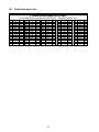
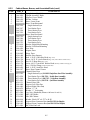
2.2 Power Requirements
AMPS PER LEG
MODEL VOLTAGE PHASE
WIRE
SERVICE
MIN.
SIZE
AWG
(mm
2
)
L1 L2 L3
H14SC 440 3 3 8 (10) 19 19 19
H14SC 480 3 3 8 (10) 17 17 17
H17SC/FPH17SC 440 3 3 6 (16) 23 23 23
H17SC/FPH17SC 480 3 3 6 (16) 21 21 21
H22SC 440 3 3 6 (16) 29 29 29
H22SC 480 3 3 6 (16) 27 27 27
The FPH17SC Navy Surface Ship electric fryers are equipped with a filter system that requires a
separate 120VAC, single-phase, 3-wire, 20 amp service (refer to wiring diagrams in sections 7.12
and 7.13).
NOTICE
If this appliance is permanently connected to fixed wiring, it must be connected by
means of copper wires having a temperature rating of not less than 167°F (75°C).
DANGER
This appliance must be connected to a power supply having the same voltage and
phase as specified on the rating plate located on the inside of the appliance door.
DANGER
All wiring connections for this appliance must be made in accordance with the
wiring diagram(s) furnished with the appliance. Refer to the wiring diagram(s)
affixed to the inside of the appliance door when installing or servicing this
equipment.
2.3 Installation
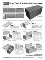
1. This equipment must be securely bolted to the deck.
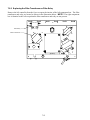
2. Install deck studs for the specific fryer configuration in accordance with the diagrams at the end
of this chapter.
3. Position the fryer on the deck studs and secure with appropriate nuts and lock washers.
DANGER
No structural material on the fryer should be altered or removed to accommodate
placement of the fryer under a hood. Questions? Call the Frymaster Dean Service
Hotline at 1-800-551-8633.

2-4
2.4 After Fryers Are Anchored At the Frying Station
DANGER
Hot oil can cause severe burns. Avoid contact. Under all circumstances, oil must be
removed from the fryer before attempting to move it to avoid oil spills, falls and
severe burns. This fryer may tip and cause personal injury if not secured in a
stationary position.
1. Close frypot drain-valve(s) and fill frypot(s) with water to the bottom oil level line.
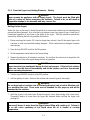
2. Boil out frypot(s) in accordance with the instructions in Section 5.1.3 of this manual.
3. Drain, clean, and fill frypot(s) with cooking oil. (See Equipment Setup and Shutdown
Procedures in Chapter 3.)
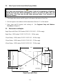
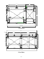
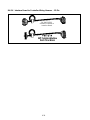
2.5 Dimensions and Weights
Single Fryer (with Filter): LWH (inches) 33.80 X 15.58 X 45.5 - 295 lbs. empty.
Single Fryer: LWH (inches) 33.38 X 15.67 X 45.5 – 190 lbs. empty.
2-Fryer Battery: LWH (inches) 33.39 X 31.45 X 45.5 – 490 lbs. empty.
3-Fryer Battery: LWH (inches) 33.24 X 47.10 X 45.5 – 570 lbs. empty.
4-Fryer Battery: LWH (inches) 33.45 X 62.55 X 45.5 – 780 lbs. empty.
24.36
24.36
10.18
2.70
15.58
14.51
16.51
2.00
Back of Fryer Unit
20.98 5.35
Front Handle
33.80
Mounting Holes
Ø .625, 4 Places
Single Fryer (with Filter)

2-5
Back of Fryer Unit
33.38
28.29
17.534
20.48
10.580
2.465
15.67
20.48
Front Handle
Mounting Holes
Ø .625,
4 Places
Single Fryer (non-filter)
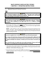
31.62
7.098
Typical
2.470
26.316
17.515
33.39
31.45
31.62
Back of Fryer Unit
Front Handle
Mounting Holes
Ø .625, 4 Places
2-Fryer Battery

2-6
7.229
17.516
27.570
14.400
33.24
32.66
32.66
47.1
22.66
22.66
Front Handle
Back of Fryer Unit
Mounting Holes
Ø .625, 4 Places
3-Fryer Battery
2.470
7.119
17.490
62.55
31.180
7.119
33.45
31.61
31.61
Front Handle
26.320
35.76
35.76
Back of Fryer Unit
Mounting Holes
Ø .625, 4 Places
4-Fryer Battery

3–1
NAVY SURFACE SHIP ELECTRIC FRYERS
CHAPTER 3: OPERATING INSTRUCTIONS
3.1 Equipment Setup and Shutdown Procedures
Setup
DANGER
Never operate the appliance with an empty frypot. The frypot must be filled with
water or cooking oil before energizing the elements. Failure to do so will result in
irreparable damage to the elements and may cause a fire.
DANGER
Remove all drops of water from the frypot before filling with cooking oil. Failure to
do so will cause spattering of hot liquid when the oil is heated to cooking
temperature.
1. Fill the frypot with cooking oil to the bottom OIL LEVEL line located on the rear of the frypot.
This will allow for oil expansion as heat is applied. Do not fill cold oil any higher than the
bottom line; overflow may occur as heat expands the oil.
NOTE: If solid shortening is used, first raise the elements, then pack the shortening into the
bottom of the frypot. Lower the elements, and then pack the shortening around and over the
elements. It may be necessary to add shortening to bring the level up to the proper mark after the
packed shortening has melted.
DANGER
Never set a complete block of solid shortening on top of the heating elements.
When using solid shortening, always pre-melt the shortening before adding it to the
frypot. If the shortening is not pre-melted, it must be packed down into the bottom of
the frypot and between the elements, and the fryer must be started in the melt-cycle
mode.
Never cancel the melt-cycle mode when using solid shortening. Doing so will result
in damage to the elements and increase the potential for a flash fire.
2. If the fryer(s) is/are not hard-wired into the power supply, ensure that the power cord(s) is/are
plugged into the appropriate receptacle(s). Verify that the face of the plug(s) is/are flush with the
outlet plate, with no portion of the prongs visible.
3. Ensure that the oil level is at the top OIL LEVEL line when the oil is at its cooking temperature.
It may be necessary to add oil to bring the level up to the proper mark, after it has reached
cooking temperature.

3–2
Shutdown
1. Turn the fryer off.
2. Filter the cooking oil and clean the fryers (See Chapters 4 and 5).
3. Place the frypot covers on the frypots.
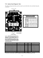
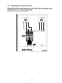
3.2 Operation of the Solid-State Analog Controller
NOTE: Refer to Chapter 4 of this manual for operating instructions for the built-in filtration system.
Fryers configured for the U.S. Navy are equipped with solid-state analog controllers.
1 3 4
5
6
2 7
U.S. Navy Solid-State Analog Controller
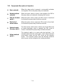
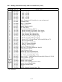
ITEM DESCRIPTION
1 Power Switch – Controls electrical power to fryer.
2 Power-On Light – Indicates when electrical power to fryer is ON.
3 Heating Mode Light – Indicates when heating element is ON.
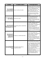
4 Trouble Light – Indicates over high-limit or problem in heat control circuitry.
5 Thermostat Control Knob – Sets desired frying temperature.
6 Hi-Limit Test Switch – Tests high-limit thermostat.
7 Second Hi-Limit Test Light – Indicates fryer is in second high-limit test mode.
The analog controller, illustrated above, is used to adjust and maintain oil at the temperature
indicated by the thermostat knob.
The fryer has two built-in high-limit protection features. If the temperature in the frypot reaches
approximately 410°F, the controller opens the heat relay circuit, turning the elements off. If the
temperature in the frypot reaches 450°F, a mechanical high-limit shuts off electrical power to the
elements. The operator should periodically test each of the high-limit protection features, using
the procedure at the end of this chapter, to verify that they are operating correctly.

3–3
The analog controller has no timing features. The operator must monitor shake and pull times.
WARNING
Before pressing the power switch to the ON position, ensure that the frypot is
properly filled with oil. See Section 3.1.
CONTROLLER OPERATING PROCEDURE
1. Verify that the thermostat knob is set to the desired cooking temperature.
2. Press the power switch to the ON position. The POWER light will illuminate.
3. If the frypot temperature is below 180°F, the controller will automatically enter a warm-up cycle
(often called a melt cycle). The heating elements will cycle on and off repeatedly, allowing the
oil to heat gradually, without scorching. During the warm-up cycle, the heating mode light will
alternately illuminate and go off as the elements cycle on and off. Within about 45 minutes, the
controller will exit the warm-up cycle and the heating mode light will remain continuously
illuminated.
4. When the oil temperature reaches the thermostat knob setpoint, the elements will cycle OFF and
the HEAT light will go off, indicating that the fryer is ready for the cooking process to begin.
HIGH-LIMIT TEST PROCEDURE
Tools Required: One 0-600°F pyrometer with sensing probe or an equivalent high-temperature
thermometer.
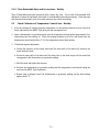
NOTE: Conduct this test when the fryer will not be needed for about one hour and when the
cooking oil is due to be changed (the test will ruin the cooking oil). Start the test with the controller
turned ON and with the cooking oil at normal frying temperature. Stir the oil thoroughly to ensure
even distribution and temperature.
DANGER
If the expected results (indicated by italics) for Steps 3 and 4 below do not occur,
turn off the fryer at the main circuit breaker panel and do not use the fryer until it has
been repaired by an authorized technician.
1. Verify that cooking oil is at the bottom OIL-LEVEL line. Add oil if necessary.
2. Turn the power switch ON and set the control knob to the normal frying temperature.
3. Insert the pyrometer probe into the frypot so that its tip is near the temperature probe on the
element (i.e., approximately 5-inches into the oil, near the center of the frypot). Press and hold
the high-limit test switch in the “1
st
” test position until the TROUBLE light illuminates. Release
the test switch.
The trouble light should have come on when the temperature was approximately 410°F (± 10°F)
and the heating elements should have de-energized (indicated by the HEAT light going out).

3–4
4. Press and hold the high-limit test switch in the “2
nd
” test position until the 2
nd
High-Limit light
illuminates. Release the switch.
The 2
nd
High-Limit light should have come on when the temperature was between 430°F and
460°F.
For fryers connected to an external shunt power supply, all fryers should have been shut off
completely and all control panel lights should have been extinguished. For fryers not connected
to an external shunt power supply, only the fryer being tested should have been shut off.
5. Place the controller power switch in the OFF position.
6. Allow the cooking oil to cool to below normal frying temperature. When the power switch is
again placed in the ON position, the elements should re-energize and the operating thermostat
should resume control of the temperature. If the TROUBLE light remains on instead, allow the
oil additional time to cool.

4-1
NAVY SURFACE SHIP ELECTRIC FRYERS
CHAPTER 4: FILTRATION INSTRUCTIONS
4.1 Introduction
The FootPrint Pro filtration system allows the cooking oil or shortening in one frypot to be safely
and efficiently filtered while the other frypots in a battery remain in operation. Section 4.2 covers
preparation of the filter system for use. Operation of the system is covered in section 4.3.
WARNING
The work center supervisor is responsible for ensuring that operators are made
aware of the inherent hazards of operating a hot oil filtering system, particularly the
aspects of oil filtration, draining and cleaning procedures.
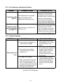
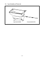
4.2 Preparing the Filter for Use
1. Rotate the pan-locking rod to either side
until it clears the filter pan, then pull the
pan out from the cabinet. Remove the
crumb tray, hold-down ring and filter
screen. Clean all components with a
solution of detergent and hot water then
dry thoroughly.
The filter pan is equipped with rollers in
rails, much like a kitchen drawer. The
pan may be removed for cleaning or to
gain access to interior components by
lifting the front of the pan to disengage
the front rollers, then pulling it forward
until the rear rollers clear the rails. The
pan cover must not be removed except
for cleaning, interior access, or to allow
a shortening disposal unit (SDU) to be
positioned under the drain.
Rotate the locking rod
to either side to allow
the pan to be pulled
out from the fryer.
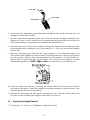
2. Inspect the filter pan connection fitting
to ensure that both O-rings are in good
condition. O-rings are located on the
tube disconnect inside the filter pan as
shown to the right.
Inspect O-Rings

4-2
3. Place the metal filter screen in the center
of the bottom of the pan, then lay a sheet
of filter paper on top of the screen, over-
lapping on all sides.
4. Position the hold-down ring over the
filter paper and lower the ring into the
pan, allowing the paper to fold up around
the ring as it is lowered to the bottom of
the pan.
Screen
Filter Paper
5. When the hold-down ring is in position, sprinkle one packet of filter powder evenly over the
paper.
6. Replace the crumb tray in the filter pan, then push the filter pan back into the fryer, positioning it
under the drain.
4.3 Operation of the Filter
DANGER
Draining and filtering of cooking oil must be accomplished with care to avoid the
possibility of a serious burn caused by careless handling. The oil to be filtered is at
or near 350°F. Ensure drain handles are in their proper position before operating
any switches or valves. Wear all appropriate safety equipment when draining and
filtering cooking oil or shortening.
DANGER
NEVER attempt to drain cooking oil from the fryer with the elements energized!
Doing so will cause irreparable damage to the elements and may cause a flash fire.
Doing so will also void the Frymaster warranty.
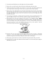
1. Ensure that the filter is prepared. See
Sec. 4.2.
2. Make sure the oil is at operating
temperature.
3. Turn the fryer power OFF. Drain the
frypot into the filter pan by rotating the
valves 90º. If necessary, use the Fryer's
Friend clean-out rod to clear the drain
from inside the frypot.
Open drain valve
by rotating 90º.

4-3
DANGER
Do not drain more than one frypot at a time into the built-in filtration unit to avoid
overflow and spillage of hot oil.
DANGER
NEVER attempt to clear a clogged drain valve from the front of the valve! Hot oil will
rush out creating the potential for severe burns. DO NOT hammer on the drain valve
with the cleanout rod or other objects. Damage to the ball inside will result in leaks
and will void the Frymaster warranty.
4. After the cooking oil has drained from
the frypot, turn the filter handle to the
ON position to start the pump and begin
the filtering process. There may be a
slight delay before the pump activates.
5. The filter pump draws the cooking oil through the filter medium and circulates it back up to and
through the frypot during a 5-minute process called polishing. Polishing cleans the oil by
trapping solid particles in the filter medium.
6. After the oil is filtered (about 5 minutes), close the drain valve and allow the fryer to refill. Let
the filter pump run 10 to 12 seconds after the oil begins to bubble. Turn the filter off.
WARNING
The filter pump is equipped with a manual reset switch (see photo below) in case the
filter motor overheats or an electrical fault occurs. If this switch trips, turn off power
to the filter system and allow the pump motor to cool 20 minutes before attempting
to reset the switch.
Filter Pump Reset Switch
7. Lower the elements into the frypot and reinstall the basket support rack. Ensure the drain
valve is fully closed. (If the drain valve is not fully closed, the fryer will not operate.) Turn
the fryer ON and allow the cooking oil to reach setpoint.
Turn filter handle
to the ON position.

4-4
DANGER
The crumb tray must be emptied into a fireproof container at the end of frying
operations each day. Some food particles can spontaneously combust if left soaking
in certain shortening.
WARNING
Do not bang fry baskets or other utensils on the fryer’s joiner strip. The strip is
present to seal the joint between the fry vessels. Banging fry baskets on the strip to
dislodge shortening will distort the strip, adversely affecting its fit. It is designed for
a tight fit and should only be removed for cleaning.
4.4 Draining and Disposing of Waste Oil
When your cooking oil has reached the end of its usable life, drain the oil into an appropriate
METAL container for transport to the disposal container. Frymaster recommends the use of the
Frymaster Shortening Disposal Unit (SDU). NOTE: If using an SDU built before January 2004
the filter pan cover must be removed to allow the unit to be positioned beneath the drain. To remove
the lid, lift up on the front edge and pull it straight out of the cabinet. Refer to the documentation
furnished with the disposal unit for specific operating instructions. If a shortening disposal unit is
not available, allow the oil to cool to 100°F, then drain the oil into a metal stockpot or similar metal
container. When draining is finished, close the fryer drain valve securely.
DANGER
Allow oil to cool to 100°F before draining into an appropriate container for disposal.
When draining oil into a disposal unit, do not fill above the maximum fill line located
on the container.
Page is loading ...
Page is loading ...
Page is loading ...
Page is loading ...
Page is loading ...
Page is loading ...
Page is loading ...
Page is loading ...
Page is loading ...
Page is loading ...
Page is loading ...
Page is loading ...
Page is loading ...
Page is loading ...
Page is loading ...
Page is loading ...
Page is loading ...
Page is loading ...
Page is loading ...
Page is loading ...
Page is loading ...
Page is loading ...
Page is loading ...
Page is loading ...
Page is loading ...
Page is loading ...
Page is loading ...
Page is loading ...
Page is loading ...
Page is loading ...
Page is loading ...
Page is loading ...
Page is loading ...
Page is loading ...
Page is loading ...
Page is loading ...
Page is loading ...
Page is loading ...
Page is loading ...
Page is loading ...
Page is loading ...
Page is loading ...
Page is loading ...
Page is loading ...
Page is loading ...
Page is loading ...
Page is loading ...
Page is loading ...
Page is loading ...
Page is loading ...
Page is loading ...
Page is loading ...
Page is loading ...
Page is loading ...
Page is loading ...
Page is loading ...
Page is loading ...
Page is loading ...
Page is loading ...
Page is loading ...
-
 1
1
-
 2
2
-
 3
3
-
 4
4
-
 5
5
-
 6
6
-
 7
7
-
 8
8
-
 9
9
-
 10
10
-
 11
11
-
 12
12
-
 13
13
-
 14
14
-
 15
15
-
 16
16
-
 17
17
-
 18
18
-
 19
19
-
 20
20
-
 21
21
-
 22
22
-
 23
23
-
 24
24
-
 25
25
-
 26
26
-
 27
27
-
 28
28
-
 29
29
-
 30
30
-
 31
31
-
 32
32
-
 33
33
-
 34
34
-
 35
35
-
 36
36
-
 37
37
-
 38
38
-
 39
39
-
 40
40
-
 41
41
-
 42
42
-
 43
43
-
 44
44
-
 45
45
-
 46
46
-
 47
47
-
 48
48
-
 49
49
-
 50
50
-
 51
51
-
 52
52
-
 53
53
-
 54
54
-
 55
55
-
 56
56
-
 57
57
-
 58
58
-
 59
59
-
 60
60
-
 61
61
-
 62
62
-
 63
63
-
 64
64
-
 65
65
-
 66
66
-
 67
67
-
 68
68
-
 69
69
-
 70
70
-
 71
71
-
 72
72
-
 73
73
-
 74
74
-
 75
75
-
 76
76
-
 77
77
-
 78
78
-
 79
79
-
 80
80


Ask a question and I''ll find the answer in the document
Finding information in a document is now easier with AI
Related papers
-
 Frymaster 8196428 User manual
-
 Frymaster H14SC User manual
-
 Frymaster BIPH14 User manual
-
 Frymaster 2836 User manual
-
 Frymaster FPPH17 User manual
-
 Frymaster RE14 User manual
-
 Frymaster e4 User manual
-
 Frymaster MPF50S Series User manual
-
 Frymaster 2836 Series Electric Fryers User manual
-
 Frymaster 2836 User manual


Other documents
-
Keating 14CM User manual
-
Keating TS User manual
-
-
Actron CP5911 Specification
-
PowerXL PAFXL-2QT User guide
-
 Plastic Development Group DB73WLG User manual
-
Imperial IFS-40-E-LOE (CE366) Owner's manual
-
SPT 30209 Operating instructions
-
Henny Penny OFE-321 Technical Manual
-
Bennett Marine ES2000 User manual
