Page is loading ...

1
Trilogy
DL4100 / DL4500 Series
Programming Instructions
WI1194B 12/04
© ALARM LOCK 2004
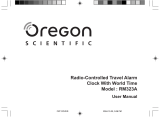
Alarm Lock Trilogy Series of
Standalone Access Control Systems
AL-IR1 PRINTER
AL-DTM
DATA TRANSFER MODULE
DL4500
"Residency Lock"
345 Bayview Avenue
Amityville, New York 11701
For Sales and Repairs 1-800-ALA-LOCK
For Technical Service 1-800-645-9440
© ALARM LOCK 2004
DL-Windows
DL4100
"Privacy Lock"

2
Table of Contents
DL Series Lock Features .................................... 3
Supported Products ........................................... 4
Lock Design Overview ....................................... 5
Terminology Used in this Manual ..................... 6
Programming Levels .......................................... 8
Conventions Used in this Manual ..................... 9
LED and Sounder Indicators ............................. 9
Product Communication Examples ................. 10
Wiring and Power Up .......................................... 11
Quick Start ............................................................ 12
Testing the Codes Entered ................................ 13
Programming Functions Overview ...................14
Programming Functions .....................................15-28
Groups and Scheduled Group 1 Examples .....29-30
Residency and Privacy Features .......................31-32
Programming Record Sheet ...............................33
User Code Record Sheet ....................................34
Schedule Record Sheet ......................................35
Glossary ................................................................36
Warranty ................................................................40
T
HE
A
LARM
L
OCK
T
RILOGY
DL-S
ERIES
S
TAND
-A
LONE
A
CCESS
C
ONTROL
S
YSTEM
IS
A
SERIES
OF
S
TATE
-
OF
-
THE
-A
RT
M
ICROPROCESSOR
-B
ASED
P
ROGRAMMABLE
K
EYPAD
-E
NTRY
S
ECURITY
L
OCKS
.
DL4100 & DL4500
Features a real-time clock/calendar that automatically adjusts for Daylight Saving Time and
allows for automated programming of events. Features three methods of programming: (1)
all features can be programmed manually through the keypad; (2) you can transfer program-
ming instructions directly from your laptop or desktop PC using DL Windows software and a
special AL-PCI cable; and (3) data can be transferred from your PC to your DL lock via the
AL DTM2 handheld Data Transfer Module. In addition, data can be retrieved from the lock in
one of three ways (1) through an infrared printer; (2) directly from the lock to the PC; or (3)
through an AL-DTM2 to your PC.
The DL Series locks include several lock types: but this manual will focus on two: the
DL4100 and DL4500. The DL4100 is a cylindrical lock, and the DL4500 is a mortise-based
lock, for extra security. Both locks allow use of "Residency" and "Privacy" features, and can
be programmed either way to suit the installation requirements. The "Residency" feature is
specially designed to prevent unintentional lock-out (typically used in retirement homes and
college dormitories), and the "Privacy" feature is designed to deny access to other users af-
ter an individual enters (typically used for rooms needing privacy from others such as bath-
rooms, dorms and meeting rooms). Out of the box (or re-started in order to load the factory
default settings), the DL4100 defaults to "Privacy" and the DL4500 defaults to "Residency".
See pages 31-32 for more information.
DL SERIES LOCKS
DL4500
DL4100

3
Audit Trail
• 40,000 Event Capacity
• Entries Logged with Time and Date
•
Critical Programming Events Logged
• Printable using the AL-IR1 Hand-Held Printer (see page 22, Function 55)
• Uploadable using Alarm Lock's DL-Windows software (see page 22, Function 58)
•
Transferable to AL-DTMs (see page 23, Function 59)
•
5000 Events with the AL-DTM2
Lock Features
•
Metal Key Override
• Keypad Lockout (see page 23, Functions 60-61)
• Non-Volatile (Fixed) Memory
•
Real-Time Clock (within one second accuracy) (see page 20, Functions 43-44)
• Programmable Relay (see page 27)
• Visual and Audible Keypad Feedback (see page 9)
•
Battery Status Monitor (see page 9)
Scheduling
•
500 Schedules with the AL-DTM2 (see pages 25-28)
•
Automated Unlock/Lock
• Enable/Disable Users (see page 16, Function 3)
• Enable/Disable Groups (see page 17)
•
Four "Quick Schedules" (contains 4 most common schedules) (see page 26)
• Real-time clock and calendar (see page 19)
• Programmable Timeout Functions (see pages 16, 18 and 20)
User Access Methods
• Keypad Entered User Codes (see pages 12, 15)
•
Metal Key Override
User Features
•
2000 Users (see page 15)
•
6 Pre-defined Administration User Levels including Master, Installer, Manager, Supervisor, Print-Only and
Basic User Codes (see page 8)
• User Code Lengths from 3-6 digits
•
Service Code (“One-Time-Only” Code) (see page 7, 16)
•
User Lockout Mode (see page 16, Function 6)
• Users Assignable to 2 Groups (see pages 18 and 29)
•
Ambush Function (see page 23, Function 66)
Keypad and Computer Programming
• All programming may be performed manually from the keypad, or from a PC using Alarm Lock's DL-
Windows Software (see page 4)
DL Series Lock Features

4
Data Transfer Module (AL-DTM)
An
AL-DTM
can be used to transfer Lock Programs (and other data) between DL-Windows and up to 48 locks.
When computers cannot be transported or when electrical power is not available, the hand-held AL-DTM device
acts as a go-between--it allows the transfer of lock data from the computer (through the AL-DTM) and to the lock,
or in reverse (from the lock through the AL-DTM back to the computer).
Infrared Printer (AL-IR1)
An
AL-IR1
printer is used to print Audit Trails and User Code lists without the need for a PC. Its infrared
reader means no cable connection to the lock is needed.
AL-DTM2 - Data Transfer Module
The enhanced
AL-DTM2
provides the same functions as the
AL-DTM
but the
AL-DTM2
may be used to
transfer program data between a PC running DL-Windows software and up to 96 locks.
Double-ended Mini Banana Plug Connector
After you create the program in DL-Windows and transfer the program from your computer to an AL-DTM,
transfer the program from the AL-DTM to the lock(s) via a double-ended mini banana plug.
DB9 to DB9 Serial Cable
Enroll User Codes into DL-Windows, then transfer this new User Code data from the computer to the AL-
PRE via this 9-pin DB9 to DB9 serial cable. Once the data is in the AL-PRE, you can transfer the data to
the lock via the double-ended mini banana plug (see above), thus avoiding the need to use an AL-PCI
cable for this process.
AL-PCI Cable
An ALARM LOCK
AL-PCI
cable is required to communicate between your computer’s RS-232 serial com-
munications port (COM 1-4) and the
AL-DTM
or lock. One end of the
AL-PCI
cable is designed to be used
on a 9-pin serial Com Port. If your computer has a 25-pin Com Port only, a 25-pin to 9-pin adapter must be
used. The other end of the
AL-PCI
cable features a 2-pin banana plug connector which is polarity sensitive-
-the TAB (marked “GND”) side must be plugged into the lock’s
black
(left) terminal.
Supported Products

5
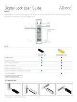
Lock Design Overview
Why Use Software inside a Lock?
With ordinary door locks, the need to make physical copies of metal keys and distributing them can be a huge organizational and financial
task -- and what will you do if someone causes a security breach by losing their key?
The answer lies in the advantage of SOFTWARE. Software (also called firmware) is not "hard" or "fixed" like hardware is. Software is
"soft" -- flexible and changeable to your needs. Software exists inside your Alarm Lock™ series lock, and can be programmed (and re-
programmed again and again) to suit your changing requirements. No more metal keys to distribute...instead, distribute User Codes --
and delete them from the software when needed. (A User Code is the software equivalent of a metal key--it is a series of numbers the
User enters into the door lock keypad to unlock the lock).
Preparing to Program your Lock
At first glance, your new DL series lock may look complicated, but it is in fact designed in a very straightforward way. The keypad
contains 12 buttons, numbers 1 through 9 plus zero, a star button (
:
) and a special "AL" button (
;
). These 12 buttons are all
you need to program your lock. In addition to manually programming your lock (using only the keypad), you can also program your
lock using a computer program called DL-Windows. DL-Windows is not needed--but it makes programming faster and easier. This
guide will show you how to program your lock using only the keypad (manually), without DL-Windows. (For more information about DL-
Windows, see User Guide OI237).
Programming your lock begins after you unpack it from the box -- there is a specific procedure outlined in "Quick Start" (page 12)
in which you "wake up" the lock to prepare it for programming. This "Quick Start" procedure shows you all the steps required to
get your lock to start working. To begin programming, you must first enter something called "Program Mode".
What is Program Mode?
Most technical people find working with "hardware" easy--they use tools to make fixes or changes to hardware. But with the soft-
ware inside the lock, you enact changes (you "interface") through the keypad. The software has only two "modes"--"Normal Mode"
and "Program Mode". When you want to make changes to the lock program, you enter "Program Mode". When you finish pro-
gramming and wish to put the lock into use, you exit Program Mode to enter "Normal Mode".
You enter Program Mode using the keypad--by pressing the Master Code of the lock that was set at the factory. The Master Code
is basically a secret passcode that allows you to enter Program Mode. But since all locks are identical and leave the factory with
the same Master Code, the factory Master Code is therefore not very secret--and should be changed to your own personal Master
Code. This way, only YOU can enter Program Mode and make changes to the lock programming.
Once the new Master Code is set , then you can continue with the Quick Start procedure and set the weekday, date and time. Af-
ter this, you can start entering User Codes for people to use. All changes to the lock are organized by their Function Number.
Want to change the date? Use Function Number 38. Want to add a User Code? Use Function Number 2. There are 99 Func-
tions in total, some that you will use often, and others that you may never need. Note: To prevent possible date and time change-
over issues, avoid entering program mode at or near midnight.
Notice that when you program your lock, programming tends to follow a
consistent 5-step pattern: (1) Enter Program Mode
(2) Press ; followed by the Function # (3) Press ; and enter data (4) Press : to end (5) Exit Program Mode.
Turn the page and learn about the special terminology used with your lock. Once that is clear, use the Quick Start proce-
dure on page 12 to help you get up and running.
Infrared LED (for Printer)
PC / AL-DTM2 Interface
Tri-Color Status LED
Special "AL" (
;
) Key
"STAR" (
:
) Key

6
Terminology Used in this Manual
What is a Lock Program?
A Lock Program contains the instructions that a lock uses to per-
form its various functions. You can use the keypad to create a
Lock Program stored within the lock. You can also use DL-
Windows (defined below) to create a Lock Program on your com-
puter, and then transfer and store the Program in the circuitry con-
tained inside the lock itself. The Lock Program is essentially a
computer database file that maintains feature settings, schedules,
audit trails, etc. Using DL Windows, Lock Programs can be cre-
ated with default information, edited on your PC, and then sent to
(and even received from) locks.
The Lock Program consists of 4 areas: User Codes, Features,
Time Zones, and Schedules, all defined below:
What are User Codes?
Also called User Access Codes or PIN No. Codes, User Codes
are numbers the User enters into the lock keypad to unlock the
lock. The User Codes are part of the Lock Program, and the Lock
Program is stored in the lock circuitry awaiting the Users to key in
their User Codes.
What are Features?
Your lock is designed to support several options and functions.
Using the keypad or DL-Windows software (the
Programmable
Features window), you can select the features you wish to acti-
vate, such as if the lock will automatically adjust for Daylight Sav-
ing Time in the spring and autumn, or if the lock sounder should be
disabled or enabled.
What is a TimeZone?
Events (recorded lock activities) can be programmed to occur at
certain times. It is these times (for example, “every Tuesday at
5PM”) that are referred to as TimeZones. In DL-Windows, you can
use the
Schedule-TimeZone
screen to create these TimeZones,
and once created, you can link events to these TimeZones.
What is a Schedule?
Your lock can be programmed to maintain a schedule in which
certain events can occur automatically. For example, you can pro-
gram the lock to allow Groups of Users (with their User Codes)
access ONLY during specific business hours. With another exam-
ple, you can program another lock to UNLOCK at 9am, LOCK at
noon for lunch, UNLOCK at 1pm, and LOCK again at 5pm--every
weekday. As you can see, many different combinations of Sched-
ules can be created to suit the needs of the Users. First you cre-
ate TimeZones (see above). Next you create events and link them
to your TimeZones (also using the Schedule-TimeZone screen in
DL-Windows). When finished, you can view (in DL-Windows) your
schedule in the Schedule View screen.
What is a User?
A User is a person who is authorized to simply use or make certain
programming changes to the lock. This User can be anyone--from
a one-time visitor (who will almost certainly have no authority to
make changes) to the owner of the building in which the lock is
installed (who will probably wish to have total authority to make
changes). The DL Series locks can hold hundreds of Users in its
programming memory, and each User possesses a pre-defined
level of authority--a Programming Level--as to their ability to use
or make changes to the lock.
What is a Programming Level?
The Programming Level defines the range of programming tasks a
User is allowed to perform. The higher the Level, the more pro-
gramming tasks the User is allowed (with Master allowing ALL
tasks).
Note: Since the Programming Level is closely associated with the
type of User and their abilities, a User who holds a certain Pro-
gramming Level is sometimes referred to by their “User Type”.
For example, DL4500 Series locks can hold up to 2000 Users in its
programming memory, and each User is associated with a User
Number (see definition of "User Number" below) and therefore a
specific Programming Level, as follows:
Master: Always associated with User Number 1. Is always en-
abled and can program all functions. (Abbreviated as
Programming Level = M).
Installer: Always associated with User Numbers 2 and 3. Can
program all functions except changing the Master Code.
(Abbreviated as Programming Level = 4).
Manager:
Always associated with User Numbers 4, 5, and 6.
Can program all functions except functions relating to lock
configuration. (Abbreviated as Programming Level = 3).
Supervisor: Always associated with User Numbers 7, 8 and 9.
Can only program functions relating to day to day operation.
(Abbreviated as Programming Level = 2).
Print Only Users: Always associated with User Numbers 10 &
11. Restricted to print event logs only. No other programming
ability allowed. (Abbreviated as Programming Level = 1).
Basic Users:
Always associated with User Number 12 and higher
(except 297-300). No programming ability allowed. Most
Users are Basic Users, who are given their own personal User
Codes and are only allowed to simply unlock the lock when
desired.
Programming Levels are hierarchical--higher levels are allowed to
do anything the levels below them can do. For example, if you are
a Manager, you are allowed to do anything that Supervisors, Print-
Only Users and Basic Users can do in addition to those tasks al-
lowed for Managers (Level 3). See page 8 for more information.
What is the Minimum Required Program Level?
This Programming Level abbreviation is the minimum program-
ming level required to access the particular Function. (The higher
the level number, the more programming tasks the User is al-
lowed, with Master allowing all tasks).
In this manual, Programming Levels for the DL series locks are
abbreviated as follows:
M
= Master,
4
= Installer,
3
= Manager,
2
= Supervisor, 1 = Print Only Users. See page 8 for more informa-
tion.
What is a User Number?
(User Number = Location Number = User Location = Slot in Lock)
User Numbers are used and are significant within each individual
lock only. The User Number determines the Programming Level
for each User. For example, DL4500 Series locks can hold up to
2000 Users in its programming memory. This memory can be
thought of as simply a numbered list from 1 through 2000. Each
entry in the list is represented by a User Number. Therefore,
where a User is located in this list--their User Location--is a com-
monly used description of their User Number. Because of their
similarities, a User Number, User Location and Location Number
can be used interchangeably. In some DL-Windows screens, the

7
word "Slot" is also used. They all mean the same thing.
Since User Numbers are fixed, knowing a User Number will spec-
ify the associated Programming Level, and will in turn indicate a
User’s programming abilities. For example, User Number 1 is
always the Master, who can perform all programming tasks.
Programming Levels are hierarchical--higher levels are allowed to
do anything the levels below them can do. For example, if you
are User 2, you are allowed to do anything that Users 3 through
11 can do. See the table on page 8 for more information.
What is a Group?
With many lock applications, it is convenient for large numbers of
similar Users to be grouped together. Placing Users into Groups
(by assigning them specific User Numbers) allows large numbers
of Users to be controlled all at once rather than individually--
saving time and effort. Groups are controlled via schedules, and
a typical example involves enabling or disabling a Group at a cer-
tain time. Default Group associations are specified in the tables
on page 8. For example, if you wish to add a User to Group 1,
assign this User a User Number between 51 and 100. These
default Group associations can be changed if needed to allow
Groups larger than the default number of 50 (by using keypad
Function 35). (See page 18 for some Group function examples).
Who are Users 297-300?
Users assigned to User Numbers 297, 298, 299 and 300 have
special abilities, as follows:
User 297: Quick Enable User 300
User 297 possesses the unique ability to enable the User Code
associated with User 300. User 297 does this by first entering
their own User 297 User Code into the lock keypad. When User
300 subsequently enters their User 300 User Code, the lock al-
lows access (for one time) and then the User 300 User Code
becomes disabled.
For example, you wish to allow one-time access to a temporary
worker. Simply enter the User 297 User Code into the lock key-
pad. Later, when the temporary worker enters the User 300
User Code into the lock keypad, the User 300 User Code allows
access (for one time only) and then becomes disabled. Later, if
you wish to grant the temporary worker re-access, simply re-
enter the User 297 User Code and the User 300 User Code will
be re-enabled (again for one time only).
User 298: Quick PC Access Code
Entering the User Code for User 298 enables that User to send
data to or from the lock. Therefore, User 298 can activate what
is the equivalent of Function 58 in Program Mode (see page 22),
without the need to enter Program Mode nor the need to know
the Master Code of the lock. An AL-PCI cable with a PC is re-
quired.
NOTE:
The User Code for User 298 is not an Access
Code.
User 299:
AL-DTM Code
This is the only User Code that will initiate data transfer with the
AL-DTM--and without allowing the User to pass through the door
(the User Code for User 299 is not an Access Code). An AL-
PCI cable and an AL-DTM (first programmed by the computer
via the DTM or DTM2 screen in DL-Windows) is required.
User 300: Temporary Access Service Code ("One-Time Only")
Temporary access User Code enabled by User 297. For exam-
ple, User Code 300 is sometimes used for guard tour duties.
See User 297: Quick Enable User 300 above.
What is DL-Windows?
DL-Windows is a computer program that allows you to program
your ALARM LOCK T3 Security Lock. You do not need DL-
Windows to program your lock, but it makes programming much
faster and easier. With DL-Windows, you can quickly create Lock
Programs (programs that make the lock perform its many func-
tions) add multiple Users (who have access), retrieve event logs,
and create Schedules. The benefit of DL-Windows is that it allows
you to set up all lock programming in advance (on your computer),
and then later send the information to the locks at your conven-
ience.
Terminology Used in this Manual (cont'd)

8
USER TYPE USER NUMBER
GROUP DEFAULT
ASSOCIATION
MINIMUM PROGRAM
LEVEL (See page 6)
Master Code 1 -
M
(All Programming Abilities)
Installer Codes 2 & 3 none
4
(Also 3, 2, 1)
Manager Codes 4 - 6 none
3
(Also 2, 1)
Supervisor Codes 7 - 9 none
2
(Also 1)
Print Only Codes 10 - 11 none
1
Basic User Codes 12 - 50 none none
Basic User Codes Group 1 51 - 100 1 none
Basic User Codes Group 2 101 - 150 2 none
Basic User Codes Group 3 151 - 200 3 none
Basic User Codes Group 4 201 - 250 4 none
Basic User Codes 251 - 296 none none
Quick Enable User 300 Code 297 none none
Quick PC Access Code 298 none none
AL-DTM Code 299 none none
Service Code 300 none none
Basic User Codes 301-2000 none none
Lock Defaults for the
DL4100 and DL4500
Users added
will default to a Group Association and a Program Level Ability as follows:
User 299 is a Non-Pass Code. This is the only code that will initiate data transfer with the AL-DTM.
NOTES:
The Programming Level defines the range of programming tasks
a User is allowed to perform. The higher the Level, the more pro-
gramming tasks the User is allowed (with Master allowing ALL
tasks).
Note: Since the Programming Level is closely associated with
the type of User and their abilities, a User who holds a certain
Programming Level is sometimes referred to by their “
User
Type
”.
For example, DL Series locks can hold hundreds of Users in its
programming memory, and each User is associated with a User
Number (see definition of "User Number" in the previous
"Terminology" section) and therefore a specific Programming
Level, as follows:
Master: Always associated with User number 1. Is always en-
abled and can program all functions. (Abbreviated as
Programming Level = M).
Installer:
Always associated with Users 2 and 3. Can program
all functions except changing the Master Code. (Abbreviated
as Programming Level = 4).
Manager: Always associated with Users 4, 5, and 6. Can pro-
gram all functions except functions relating to lock
configuration. (Abbreviated as Programming Level = 3).
Supervisor: Always associated with Users 7, 8 and 9. Can only
program functions relating to day to day operation.
(Abbreviated as Programming Level = 2).
Print Only Users: Always associated with Users 10 & 11.
Restricted to print audit trails only. No other programming
ability allowed. (Abbreviated as Programming Level = 1).
Basic Users: Always associated with User number 12 and
higher (except 297-300). No programming ability allowed.
Programming Levels are hierarchical--higher levels are allowed to
do anything the levels below them can do. For example, if you
are a Manager, you are allowed to do anything that Supervisors,
Print-Only Users and Basic Users can do in addition to those
tasks allowed for Managers (Level 3).
Programming Levels

9
ACTIVITY LED SOUNDER COMMENTS
Keypress 1 RED Flash 1 Beep Normal Operation
Access Granted 3 GREEN Flashes 3 Beeps
Invalid Code 6 RED Flashes 6 Beeps Re-enter User Code
Successful Program Entry 2 GREEN Flashes 2 Beeps When in Program Mode
Unsuccessful Program Entry 7 RED Flashes 7 Beeps When in Program Mode
Exit Program Mode Flashes: 1 Red, 2 Green,
then 1 Red
10 Beeps "73" in Continuous Wave
(Morse Code)
Valid but Disabled Code 1 Green, 4 Red Flashes 1 long, 5 short beeps Code exists in memory, but disabled
Low Battery Yellow Flash during key
presses
Long Beep See page 11 before changing batteries
User Code Entered Yellow Flash Sequence of 7 Beeps
Repeated 4 Times
Non-fatal memory or clock error has been
detected. Under this condition,
unexpected operation is possible. Re-
move power and restart.
Inside Lever Depressed and held down 7 Red Flashes, 1 Red Flash 7 Beeps. 1 Beep Example: Inside lever not released for 5
seconds after User Code access granted.
Outside Lever Depressed and held down 7 Red Flashes, 2 Red
Flashes
7 Beeps. 2 Beeps Example. Outside lever depressed for 5
seconds after User Code access denied.
Deadbolt Engaged / Button Pressed and
button held down
7 Red Flashes, 3 Red
Flashes
7 Beeps. 3 Beeps Example: Valid User Code entered while
Deadbolt extended.
Programming Key Sequence
.
Programming
Information
General Program Mode Information
If a wrong key is pressed during code entry, hold any key continuously until the error sound is heard (7 short beeps), this will clear the entry. Re-enter the key
sequence again.
All program sequences are followed by the
:
key; 2 short beeps indicate a successful program sequence.
Enabling/Disabling Users (By User Number)
3. Disable User
;
3
;
[ _ _ _ ]
:
4. Enable User
;
4
;
[ _ _ _ ]
:
User Number must be between 2 and 2000.
NOTE: Will Enable/Disable users even if the user is associated with an enabled group.
2
Conventions Used in this Manual
LED and Sounder Indicators
The DL Series locks provide visual and audible keypad feedback. With a fully charged battery, the LED and sounder feedback
is as follows:
Minimum Required Program Level
Program Levels are abbreviated as follows:
M
= Master
4
= Installer
3
= Manager
2
= Supervisor
1
= Print Only Users
This Program Level abbreviation is the
minimum
program level required to
access the particular Function. (The
higher the level, the more programming
tasks the User is allowed, with
Master
allowing all tasks).
Function
Description
Function
Number
Function Name

10
NOTE:
The AL-PCI cable is designed to be used on a 9 pin serial COM port. If your computer has a 25 pin COM port, a 25 pin to 9 pin adapter must be used.
Warning:
Polarity MUST be observed when connecting cables to the lock. The tab (-) must plug into the negative (black) hole.
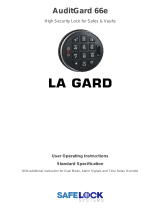
Scenario 4
Use the AL-IR1 Infrared printer to print your lock’s audit trail (event log), User Code list, clock settings and software
version. No cable required.
AL-IR1
INFRARED PRINTER
Scenario 1
Create the program in DL-Windows on your computer, then transfer the program from the computer directly to the lock via an
AL-PCI cable. You must always enter the User 298 User Code to send or receive data Using DL-Windows.
IBM COMPATABLE
LAPTOP OR DESKTOP PC
NOTE:
OBSERVE TAB DIRECTION WHEN
INSERTING CABLE INTO LOCK
AL-PCI CABLE
CONNECT TO SERIAL PORT
(COM 1-4)
Scenario 2
Create the program in DL-Windows and transfer the program from your computer to an AL-DTM (via an AL-PCI cable)…
then transfer the program from the AL-DTM to the lock(s) (via a double-ended mini banana plug). The hand-held AL-DTM is useful
because you do not have to transport (or find electricity for) your computer. Data can also flow in reverse, from the lock, through
the AL-DTM, back to the computer for examination.
IBM COMPATABLE
LAPTOP OR DESKTOP PC
NOTE:
OBSERVE TAB DIRECTION WHEN
INSERTING CABLE INTO LOCK
AL-PCI CABLE
CONNECT TO SERIAL PORT
(COM 1-4)
AL-DTM DATA
TRANSFER
MODULE
NOTE:
OBSERVE TAB DIREC-
TION WHEN INSERTING CABLE
INTO AL-DTM AND LOCK
DOUBLE-ENDED MINI BANANA
PLUG CONNECTOR
Product Communication Examples
Send to lock
Receive from lock
DL4500 LOCK
DL4500 LOCK
DL4500 LOCK

11
WIRING
See the Installation Manual for more information.
Batteries:
Use only 1.5 volt Duracell Alkaline size-AA batteries.
External Power:
Red / Black wires - External 7.5 VDC Power Source
must be used for operation without batteries in the
lock. Use an external UL-Listed power supply pro-
vided with backup battery power and current limiting
protection that is approved for the application.
Relay:
COM-Blue / NO-Yellow / NC-Green - See page 24
(Function 67) for programming options for the Relay.
Wiring to Disarm a Burglary Control Panel
Burglary Control Panel wiring. See page 27.
POWER UP
•
When applying power to the lock for the first time
, stop
and follow the procedure outlined in "Quick Start, First time
Power Up" further in this manual.
•
When power is re-applied to a lock that was already op-
erational, proceed as follows:
1. Disconnect battery pack connector.
2. With battery power disconnected, press
and hold
down
; for 10 seconds to insure discharge of all ca-
pacitors.
3. Re-connect battery pack (lock will sound 3 short beeps). If
beeps are not heard, then restart at step 1.
4. Do not press any keys for 15 seconds.
5. After 15 seconds, the LED will flash red 6 times and 6
beeps will sound.
The lock is now ready for use. The pre-existing program is
loaded from fixed memory. Set the clock using functions 38,
39 and 40.
ERASE ALL PROGRAMMING
(The "out of box" factory default will be loaded)
1. Remove the battery pack.
2. With battery power disconnected, press
and hold
down
;
for 10 seconds to ensure discharge of all ca-
pacitors.
3. Re-install the battery pack (lock will sound 3 short beeps).
If beeps are not heard, then restart at step 1.
4. Within 5 seconds after hearing the 3 short beeps, press
and hold
; until the lock begins to beep, then release.
5. A series of 5 RED LED and 5 beeps will be heard followed
by 10 seconds of silence, then 3 GREEN LEDs and 3 fast
beeps.
All settings and programming have been erased and the lock is
now ready for use. Note: All lock programming can also be
erased (without need to disconnect the batteries) by entering
Function 99.
BATTERY REPLACEMENT
When a valid code is entered and the batteries are weak, the
yellow LED will light and the sounder will sound for 4 seconds.
DL Series locks use five (5) AA-size 1.5 volt alkaline batteries.
Always replace weak batteries as soon as possible.
CAUTION: Do not press any keys while batteries are dis-
connected or you may erase the real-time clock settings.
1. At the back of the lock, remove the screw at the bottom of
the lock housing and remove the cover.
2. Pull out the battery pack and quickly replace all 5 batteries -
within 1 minute.
3. If you
do not
hear the 3 beeps when power is re-applied,
all programming and settings have been retained, and the
lock is ready for use. Go to step 5.
4. If you do hear 3 beeps when power is re-applied, do not
press any keys for 15 seconds
. After the 15 second
period, the LED will flash red 6 times and 6 beeps will
sound. Reset the clock using functions 38, 39 and 40.
5. Replace the cover and tighten the screw.
Wiring and Power Up

12
Quick Start
First Time Start Up
1. Unpack the lock.
2. With the batteries disconnected, hold down the ; key for 10 seconds and release.
3. Connect the batteries and listen for 3 beeps. Within 5 seconds of hearing the 3 beeps, press and hold ; until beeping
starts. This will clear the lock of all programmed data. Important: If you do not hear these 3 beeps, you must start over at
step 2.
4. Listen for another series of beeps and LED flashes followed by 10 seconds of silence. The lock is now ready to program.
Failure to follow this exact procedure can result in erratic lock behavior. Important Note: When entering any key se-
quence below, do not pause more than 25 seconds between any key presses--otherwise you must start again.
Enter Program Mode and Change Factory Master Code
1. Press the default Master Code: 1 2 3 4 5 6.
2. Wait for the green light and press
;
until multiple beeps are heard. You are now in Program Mode.
Note:
The lock will beep every 6 seconds as a reminder that you are in Program Mode.
3. Enter a new personal 6-digit Master Code number by pressing the following keys:
; 1 ; [
new Master Code
] ; [
new Master Code
] : (the second set of digits must be exactly the same).
(For example, if you want your new Master Code to be “664433”. Press:
;
1
;
664433
;
664433
:
).
Now that the Master Code has been changed, there is no need to change it again (unless you want to). Since you are
still in Program Mode, you can now proceed directly below and program various functions.
Note:
Programming any
Function, such as setting the clock, follows a consistent 5-step pattern: (1) Enter Program Mode (2) Press
;
[Function #] (3) Press ; and enter data (4) Press : to end (5) Exit Program Mode.
Note: There is a 3 minute Program Mode timeout if no keys are pressed when in Program Mode. A steady tone will sound
for the final 15 seconds of the 3 minute timeout period as a warning. To remain in Program Mode, press any key.
Note:
To prevent possible date and time changeover issues, avoid entering program mode at or near midnight.
Set the Weekday
1. Enter Program Mode (if not in already).
2. Press
;
40
;
[
number of weekday
]
:
. (Use 1= Sunday, 7 = Saturday).
(For example - Friday - press
;
40
;
6
:
).
Set the Date
1. Enter Program Mode (if not in already).
2. Press ; 38 ; [
MMDDYY
] :.
(For example - May 10, 2002 - press ; 38 ; 051002 :).
Set the Time
1. Enter Program Mode (if not in already. If you just finished the above procedure, you are still in Program Mode).
2. Press
;
39
;
[
HHMM
]
:
. (Use 24-hour military format, where PM adds 12 hours).
(For example - 2:30pm - press
;
39
;
1430
:
).
Enter User Codes
1. Enter Program Mode (if not in already).
2. Press
;
2
;
[
User Number
]
;
[
new User Code
]
:
.
(For example, John Smith is designated as User 21. You want him to use the code of “232323” to unlock the door.
Program the lock by pressing:
;
2
;
21
;
232323
:
).
3. Repeat step 2 for each new user.
Delete a User Code
1. Enter Program Mode (if not in already).

13
Quick Start (cont’d)
2. Press
;
2
;
[
User Number
]
:
.
The lock will flash a green LED and beep continuously for 6 seconds. When the red LED flashes, the User Code is deleted.
3. Repeat step 2 for each new User.
User Code Conflicts
Care should be taken not to program a new User Code which matches the first digits of any other User Code (only the User
Code with the least number of digits will be recognized).
Example:
If User Codes 123 and 123456 are both entered in the
system, only code 123 would be recognized, unless the ENTER Key has been enabled (see Function 69, see page 25). In ad-
dition, an error will sound if you try to program a new User Code that matches the first digits of the Master Code.
WARNING: When attempting to change an existing Master Code, it is HIGHLY recommended that you enable all
Groups (see Function 23), exit Program Mode, and enter the new anticipated Master Code to verify that the anticipated
sequence does not currently open the lock. If the lock does not open, the anticipated Master Code can be used as the
new Master Code; if the lock opens, the anticipated Master Code already exists in the lock (as a User Code), and the
anticipated Mater Code should NOT be used. Always repeat this procedure with any new anticipated Master Codes.
Exit Program Mode
Hold Down any key for 3 seconds. Program Mode exit is confirmed by several beeps. You are now in normal operation.
Re-enter Program Mode
If you wish to re-enter Program Mode, key-in your new 6-digit Master Code, and press ;.
You are now ready to mount and install your DL series lock and give out your User Codes. Before installation, it is suggested
you test and verify that all User Codes entered are active (see below).
Verifying Basic Keypad User Codes
Test a valid User Code:
VALID CODE -
The Green LED will flash momentarily and the sounder will beep a few times after a valid code is entered.
INVALID CODE -
The RED LED will flash several times and the sounder will beep several times after an invalid code is entered.
Use Function 2 to re-program the code.
Testing the Codes Entered

14
Function 1 Change Master Code
See page 15
Function 2 Add/Delete/Change User Codes
See page 15
Function 3 User Disable (By User Number)
See page 16
Function 4 User Enable (By User Number)
See page 16
Function 5 User Enable with Timeout
See page 16
Function 6 Enable Total User Lockout
See page 16
Function 7 Disable Total User Lockout
See page 16
Function 8 Reserved
---
Function 9 Enable User 300 (Service Code)
See page 16
Function 10 Erase All Users Except the
Master Code
See page 16
Function 11 Reserved
---
Function 12 Clear All Schedules and Timeout
Functions
See page 17
Function 13 Clear All Timeout Functions
See page 17
Function 14 - 17 Group 1-4 Disable
See page 17
Function 18 Disable All Groups
See page 17
Function 19 - 22 Group 1-4 Enable
See page 17
Function 23 Enable All Groups
See page 17
Function 24 Reserved
---
Function 25 - 28 Group Disable with Timeout
See page 18
Function 29 Disable All Groups with Timeout
See page 18
Function 30 - 33 Group Enable with Timeout
See page 18
Function 34 Disable All Groups with Timeout
See page 18
Function 35 Group Add/Delete Association
See page 18
Function 36 - 37 Reserved
---
Function 38 Set Date
See page 19
Function 39 Set Time
See page 19
Function 40 Set Weekday
See page 19
Function 41 Set Daylight Savings Time
See page 19
Function 42 Reserved
---
Function 43 Speed Up Clock
See page 20
Function 44 Slow Down Clock
See page 20
Function 45 - 46 Passage Mode Enable/Disable
See page 20
Function 47 Timed Passage Mode
See page 20
Programming Functions--Overview
Function 48 Enable Permenent Passage Mode
See page 21
Function 49 Disable Permenent Passage
Mode
See page 21
Function 50 Return Lock to Normal Passage
Mode Schedule
See page 21
Function 51 Passage Mode Configuration
See page 21
Function 52 - 54 Pass Time
See page 21
Function 55 Print Audit Trail
See page 22
Function 56 Print User Code List
See page 22
Function 57 Print Clock Settings and Software
Version
See page 22
Function 58 Upload/Download PC Data
See page 22
Function 59 AL-DTM2 Door Number
See page 23
Function 60 Number of Attempt Before
Lockout
See page 23
Function 61 Set the Attempts Lockout Time
See page 23
Function 62 - 63 Reserved
---
Function 64 - 65 Reserved
---
Function 66 Ambush Code
See page 23
Function 67 Add Relay/System Features
See page 24
Function 68 Delete All Relay Functions and
System Options added by
Function 67. Also Privacy Time-
out duration.
See page 24
Function 69 - 70 Enable/Disable Enter Key
See page 25
Function 71 Reserved
---
Function 72 - 73 Scheduled Enable/Disable
Passage Mode
See page 25
Function 74 - 77 Schedule Enable Group 1 - 4
See page 25
Function 78 Schedule Enable All Groups
See page 25
Function 79 - 82 Schedule Disable Group 1 - 4
See page 25
Function 83 Schedule Disable All Groups
See page 25
Function 84 - 87 Quick Schedules - Enable Group
See page 26
Function 88 Passage Mode
(Open Time Window)
See page 26
Function 89 Passage Mode
(Close Time Window)
See page 26
Function 90 Relay Activation
(Open Time Window)
See page 27
Function 91 Relay Activation
(Close Time Window)
See page 27
Function 92 Enable Group 4
(Open Time Window)
See page 28
Function 93 Enable Group 4
(Close Time Window)
See page 28
Function 94 - 98 Reserved
---
Function 99 Clear All Lock Programming
See page 28

15
1. New Master Code
(User Number 1)
2. Add/Delete/Change User Codes 2-2000
; 1 ;
[ _ _ _ _ _ _ ]
; [ _ _ _ _ _ _ ] :
(New Master Code) (Confirm New Master Code)
; 2 ;
[ _ _ _ _ ] * ; [ _ _ _ _ _ _ ] :
(User Number) (User Code)
•
User Number must be between 2 and 2000.
•
To delete a code/card, leave the User Code blank and wait for the rapid beeping to stop.
•
User Code must be 3-6 digits.
•
Each User Code can be thought of as a person. As long as each person possesses their own
unique User Code, you can control access to the lock by adding or deleting User Codes. See
"Terminology Used in this Manual" on page 6 for more information.
•
Master Code must be 6 digits-only.
•
Master Code is Keypad Code Access only.
•
Factory Default =
123456
•
See "Lock Design Overview" on page 5 for more information about Master Codes.
3
M
USERS
Lock Defaults for the
DL4100 and DL4500
See page 8. Users added
will default to a Group Association and a Program Level Ability as follows:
USER TYPE USER NUMBER GROUP DEFAULT MINIMUM PROGRAM
Master 1 -
M
(All Programming Abilities)
Installers 2 & 3 none
4
(Also 3, 2, 1)
Managers 4 - 6 none
3
(Also 2, 1)
Supervisors 7 - 9 none
2
(Also 1)
Print Only Users 10 - 11 none
1
Basic Users 12 - 50 none none
Basic Users in Group 1 51 - 100 1 none
Basic Users in Group 2 101 - 150 2 none
Basic Users in Group 3 151 - 200 3 none
Basic Users in Group 4 201 - 250 4 none
Basic Users 251 - 296 none none
Quick Enable User 300 297 none none
Quick PC Access 298 none none
AL-DTM2 Code 299 none none
Service User 300 none none
Basic Users 301-2000 none none
Programming Functions
User 299 is a Non-Pass Code. This is the only code that will initiate data transfer with the AL-DTM.

16
USERS (Continued)
; 6 :
6. Enable Total User Lockout Mode
(This Function enabled through keypad only)
Note:
Do not use this function with Passage Mode.
7. Disable Total User Lockout Mode
(This Function enabled through keypad only)
; 7 :
User Lockout Mode
Prevents all User Codes (Except User 1 Code) from operating the lock.
Note:
No other programming
functions or schedules will re-enable Users. Users must
be re-enabled with Function 7.
Note:
Does not change the User enable/disable status.
Note:
If the lock is currently in Passage Mode
(door "unlocked") and Function 6 is programmed, the lock will remain in Passage Mode.
M
5. User Enable with Timeout
(Enter Timeout, XXX Hours)
(This Function enabled through keypad only)
; 5 ; [ _ _ _ _ ]
; [ _ _ _ _ ] :
(User Number) (XXX Hours)
•
With Function 5, User Numbers must be between 2-2000, hours must be between 1-999.
•
Function 5 can
temporarily
override a disabled User (disabled using Function 3 above).
•
Since this is a temporary feature, Function 5 can only be enabled using the keypad.
•
Example:
Brian, User Number 1157, rarely works at the office, but when he does, enable him for his 8 hour work day by entering
Program Mode and pressing:
;
5
;
1157
;
008
:
.
•
NOTE:
Up to 4 Timeout Functions may be pending at any one time. An error beep will sound when attempting to program more
than 4 Timeout Functions.
2
Service Code is a One-Time-Only Code. Once it is used, it is disabled until enabled again.
NOTE:
User Number 297 is used to reset Service Code Use. See "Terminology Used in
this Manual" on page 7 for more information and examples regarding special Users 297-300.
; 9 :
9. Enable User 300
(Service Code)
2
2
; 1 0 ; 0 0 0 :
10. Erase All Users Except the Master Code
(User 1)
(This Function enabled through keypad only)
Erases all User Codes except the Master Code (User 1).
•
Function 10 can only be performed using the keypad.
M
11. Reserved
3. Disable User
; 3 ; [ _ _ _ _ ] :
(User Number)
4. Enable User
; 4 ;
[ _ _ _ _ ]
:
(User Number)
User Enable/Disable
(By User Number)
•
User Number must be between 2 and 2000.
NOTE:
Will Enable/Disable Users even if the User is associated with an enabled Group. Use Feature 3 to disable a specific User
Number and their associated User Code. If the disabled User Code is entered, the lock will flash 1 Green and 4 Red Flashes (with
1 long and 5 short beeps) indicating that the User Code exists in memory, but is disabled. Function 4 will "undo" Function 3.
2
8. Reserved
Programming Functions (cont'd)

17
; 1 2 ; 0 0 0
:
12. Clear All Schedules and Timeout Functions
Function 12 clears all programmed
Schedules
and all
Timeout Functions
. (To clear All Timeout Functions only, see
Function 13 below). Function 12 will clear all of the following: All Schedule Functions 72 through 93, Timeout Functions
5, 25 through 34 and Function 47.
Note:
Function 12 also resets Passage Mode and any disabled Groups. After using
Function 12, your Scheduled/Timeout features must be manually re-programmed.
NOTE:
Up to 4 Timeout Functions may be pending at any one time. An error beep will sound when attempting to
program more than 4 Timeout Functions.
3
; 1 3 ; 0 0 0
:
Function 13 clears all
Timeout Functions
. (To clear All Schedules and Timeout Functions, see Function 12 above).
Function 13 will clear all of the following: All Timeout Functions 5, 25-34 and Function 47. After using Function 12, your
Scheduled/Timeout features must be manually re-programmed.
NOTE:
Up to 4 Timeout Functions may be pending at any one time. An error beep will sound when attempting to
program more than 4 Timeout Functions.
3
13. Clear All Timeout Functions
(This Function enabled through keypad only)
CLEAR FUNCTIONS
Group Enable/Disable
Enter the functions below to Enable/Disable Groups. Functions 14 - 23 will each override
existing scheduled events. Therefore, Functions 14 - 23 are temporary, take effect im-
mediately, and are always overridden by future scheduled events that already exist within
the lock programming.
2
GROUPS
24. Reserved
; 1 4 :
; 1 5 :
16.
Disable Group 3
; 1 6 :
17.
Disable Group 4
; 1 7 :
18.
Disable All Groups
; 1 8 :
19. Enable Group 1
; 1 9 :
20. Enable Group 2
; 2 0 :
21. Enable Group 3
; 2 1 :
22. Enable Group 4
; 2 2 :
23. Enable All Groups
; 2 3 :
14.
Disable Group 1
15. Disable Group 2
Programming Functions (cont'd)
Important:
It is the responsibility of the lock programmer to verify the proper lock/unlock conditions and Group conditions
after programming the lock with Function 12 and 13.
PRIORITY ORDER
1. Disabled Users
2. Enabled Groups
3. Disabled Groups
4. Enabled Users
The Priority Order details which Function will
take effect before ("have priority over") others.
For example, as per the list above, Enabled
Users have the lowest priority, and other Func-
tions can affect the status of these Users. Dis-
abling a Group (Functions 14-18) will take pri-
ority over the enabled Users in that Group,
disabling them. Enabling Groups (Functions
19-23) will take priority over those tasks lower
in the list, and finally disabling a User (Function
3) takes priority over all other tasks listed.

18
GROUPS
Group Enable/Disable with Timeout
(Enter Timeout, XXX Hours)
(Functions 25-34 are enabled through the keypad only)
•
Hours must be between 1-999. Enter the functions below to Enable/Disable Groups for the amount of time entered in hours.
NOTE:
Only 4 Timeout Functions are allowed at any one time. An error beep will sound when attempting to program more than
4 Timeout Functions. Functions 25 - 34 will each override existing scheduled events. Therefore, Functions 25 - 34 are tem-
porary, take effect immediately, and are always overridden by future scheduled events that already exist within the lock
programming.
NOTE:
Functions 25-34 are enabled through the keypad only.
•
Example:
All 15 members of the Accounting Department are members of Group 4, and a schedule programmed in the
department's door lock reflects their normal working hours of 9 AM through 5 PM, Monday through Friday. But one day a
special event occurs, and all Accounting Department members are requested to stay an extra hour until 6 PM. Therefore,
at 5 PM, the manager (wishing to temporarily enable Group 4 users for an extra hour) enters Program Mode and
presses:
;
33
;
001
:
. Likewise, if the manager wished to send his department home
early at 3 PM, the manager could enter
;
28
;
002
:
.
2
; 3 5 ; [ _ _ _ ] ; [ _ _ _ _ ]
:
(User Number) (Groups)
35. Group Add/Delete Association
As per the chart on page 8, the lock's default programming from the factory associates certain User Numbers with certain
Groups. To override these default Group associations, Function 35 manually associates (or disassociates) a selected
User with a selected Group. During programming, Groups not selected are then disassociated from the User. Function
35 is helpful when the number of Users you wish to add to a Group outgrows the number of User Numbers defaulted to a
Group (50); or if an existing User joins a department and you wish to simply add them to a Group.
•
User Number must be between 2 and 2000; Groups 1-4 (to associate with User) may be selected.
Add Example
: To associate User 67 with Groups 1, 2 and 4;
Enter:
; 3 5 ; 6 7 ; 1 2 4 :
Delete Example
: To remove all Group associations for User 67;
Enter:
; 3 5 ; 6 7 :
NOTE:
If a User is associated with more than one Group,
all
associated Groups would have to be disabled before the User is disabled.
; 2 5 ; [ _ _ _ ] :
(XXX Hours)
25. Timed Disable Group 1
; 2 6 ;
[ _ _ _ ]
:
(XXX Hours)
26.
Timed Disable Group 2
; 2 7 ;
[ _ _ _ ]
:
(XXX Hours)
27.
Timed Disable Group 3
; 2 8 ; [ _ _ _ ] :
(XXX Hours)
28. Timed Disable Group 4
; 2 9 ; [ _ _ _ ] :
(XXX Hours)
29. Timed Disable All Groups
; 3 0 ; [ _ _ _ ] :
(XXX Hours)
30. Timed Enable Group 1
; 3 1 ;
[ _ _ _ ]
:
(XXX Hours)
31. Timed Enable Group 2
; 3 2 ;
[ _ _ _ ]
:
(XXX Hours)
32.
Timed Enable Group 3
; 3 3 ; [ _ _ _ ] :
(XXX Hours)
33. Timed Enable Group 4
; 3 4 ; [ _ _ _ ] :
(XXX Hours)
34. Timed Enable All Groups
3
36 - 37. Reserved
Clear All Timeout Functions by entering Function 13.
NOTE:
Programming Functions (cont'd)

19
; 3 8 ;
[ _ _ _ _ _ _ ]
:
(Date)
38. Set Date
42. Reserved
•
Use Month Day Year format - MMDDYY - Single digit months and days are entered with
a preceding zero.
•
Enter ONLY the last two digits of the year.
For Example:
March 8, 2002;
Enter:
; 3 8 ; 0 3 0 8 0 2 :
3
39. Set Time
; 3 9 ; [ _ _ _ _ ] :
(Time)
•
Time must be 4 digits
•
Use 24 Hour Format (add 12 hours to program PM time).
For Example:
To set time to 8:25 PM;
Enter:
; 3 9 ; 2 0 2 5 :
For Example:
To set time to 8:25 AM;
Enter:
; 3 9 ; 0 8 2 5 :
3
; 4 0 ;
[ _ ]
:
(Day)
40. Set Weekday
•
For day enter: 1 for Sunday, 2 for Monday, 3 for Tuesday, 4 for Wednesday, 5 for Thursday,
6 for Friday
and 7 for Saturday.
For Example:
To set day to Sunday;
Enter:
; 4 0 ; 1 :
3
41. Set Daylight Saving Time
; 4 1 ;
[ _ _ ]
:
(DST Mode)
NOTE:
Daylight Saving Time (DST) adjustment is programmable as shown in the table below.
All modes adjust time at 2AM.
*
Default DST Mode is 12.
4
CLOCK SETTINGS
DST Mode Time Forwarded Time Regressed
01
02 1st Sunday in March 4th Tuesday in Sept.
03 Last Sat. in March Last Sat. in Sept.
04 Last Sunday in March Last Sunday in Sept.
05 Last Sunday in March 4th Sunday in Oct.
06 Last Sunday in March Last Sunday in Oct.
07 Last Sunday in March 1st Sunday in Sept.
08 April 1st September 30th
09 April 1st October 1st
10 April 1st Last Sunday in Oct.
11 1st Sunday in April 2nd Sunday in Oct.
*
12 (U.S.A. & Canada)
1st Sunday in April Last Sunday in Oct.
No DST Adjustment
DST Mode Time Forwarded Time Regressed
13 Last Friday in April Last Thurs. in Sept.
14 May 1st September 30th
15 1st Sunday in Sept. 1st Sunday in April
16 2nd Tuesday in Sept. 3rd Tuesday in April
17 1st Sunday in Oct. Last Sunday in Feb.
18 1st Sunday in Oct. 3rd Sunday in March
19 1st Sunday in Oct. Last Sunday in Mar.
20 2nd Sunday in Oct. 2nd Sunday in Mar.
21 3rd Sunday in Oct. 2nd Sunday in Feb.
22 Last Sunday in Oct. 1st Sunday in March
23 Last Sunday in Oct. Last Sunday in Mar.
24 1st Sunday in Nov. Last Sunday in Feb.
Programming Functions (cont'd)

20
CLOCK ADJUST
; 4 3 ; [ _ _ ] :
(seconds)
43. Speed Up Clock
(This Function enabled through keypad only)
; 4 4 ;
[ _ _ ]
:
(seconds)
44. Slow Down Clock
(This Function enabled through keypad only)
Number of seconds to adjust (speed up/slow down) the clock each day must be between
0-55 seconds.
Always consider the current setting when using this function, because this function is not
cumulative. For example, if the clock needs to be sped up 10 seconds per day and the
current setting is already 10, program 20 seconds using Function 43 (below).
Example 1
: Clock is losing 13 seconds every day, enter:
; 4 3 ; 1 3 :
.
This example assumes that the Clock Adjust setting was at the factory default of zero.
Function 57 can be used to print the current Clock Adjust setting.
Example 2
: Clock is gaining 13 seconds every day, enter:
; 4 4 ; 1 3 :
.
This example assumes that the Clock Adjust setting was at the factory default of zero.
Function 57 can be used to print the current Clock Adjust setting.
Example 3
: To set the clock adjust setting back to the factory default of zero, enter
:
; 4 3 :
or
; 4 4 :
NOTE:
Subsequent use of these functions are not cumulative.
Clock Adjust
4
; 4 5 :
45. Enable Passage Mode
(This Function enabled through keypad only)
; 4 6 :
46. Disable Passage Mode
(This Function enabled through keypad only)
47. Timed Passage Mode
(This Function enabled through keypad only)
; 4 7 ; [ _ _ _ ] :
(XXX Hours)
•
Function 45 allows passage through the door without the need for a User Code. Re-Lock using Function 46.
•
Programmed Schedules will override the state of the lock when Functions 45 and 46 are used. If it is required that
programmed schedules do not
override Passage Mode, enable/disable Passage Mode using Functions 48/49.
Note:
Be-
cause of the temporary nature of these features, Functions 45-47 can only be enabled using the keypad.
Passage Mode Enable/Disable - Schedule will Override
2
•
Hours must be between 1 - 999.
Function 47 allows passage through the door without the need for a User Code for the programmed amount of time.
•
For example, if you wish your office door lock to be unlocked (unlocked = "Passage Mode") for the next 3 hours,
enter Program Mode and press:
;
47
;
003
:
2
PASSAGE MODE
Programming Functions (cont'd)
/