Carl Goldberg GPMA1967 Owner's manual
- Category
- Toys & accessories
- Type
- Owner's manual
This manual is also suitable for

1
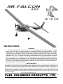
INSTRUCTIONS
WARNING
A radio-controlled model is not a toy and is not intended for persons under 16 years old. Keep
this kit out of the reach of younger children, as it contains parts that could be dangerous. A radio-
controlled model is capable of causing serious bodily injury and property damage. It is the buyer's
responsibility to assemble this aircraft correctly and to properly install the motor, radio, and all other
equipment. Test and fly the finished model only in the presence and with the assistance of another
experienced R/C flyer. The model must always be operated and flown using great care and common
sense, as well as in accordance with the Safety Code of the Academy of Model Aeronautics
(www.modelaircraft.org). We suggest you join the AMA and become properly insured prior to flying
this model. Also, consult with the AMA or your local hobby dealer to find an experienced instructor in
your area. Per the Federal Communications Commission, you are required to use only those radio fre-
quencies specified "for Model Aircraft."
LIMITED WARRANTY
Carl Goldberg Products has inspected and certified the components of this aircraft. The company urges the buyer to perform his
own inspection, prior to assembly, and to immediately request a replacement of any parts he believes to be defective for their
intended use. The company warrants replacement of any such components, provided the buyer requests such replacement with-
in a period of 90 days from the date of purchase and provided the defective part is returned, if so requested by the company.
No other warranty, expressed or implied, is made by the company with respect to this kit. The buyer acknowledges and under-
stands that it is his responsibility to carefully assemble the finished flying model airplane and to fly it safely. The buyer hereby
assumes full responsibility for the risk and all liability for personal or property damage or injury arising out of the buyer's use of the
components of this kit.
CARL GOLDBERG PRODUCTS, LTD.
P.O. Box 88 Oakwood GA 30566 Phone #678-450-0085 Fax # 770-532-2163 www.carlgoldbergproducts.com
© Copyright 2004 Carl Goldberg Products LTD
TM

2
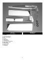
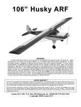
Parts List
(Items Shown)
Hardware List
(Not Shown)
1. Fuselage
2. Wings with Ailerons
3. Stab with Elevators
4. Fin
5. Rudder
6. Tank Hatch
7. Dihedral Brace
8. Fuel Tank with hardware
9. Main Landing Gear
10. Nose Gear
11. Clear Canopy
12. Wheels (3)
13. Pushrods

3
ITEMS NEEDED TO COMPLETE THIS AIRCRAFT
1 RADIO GUIDANCE SYSTEM (4 CHANNEL
MINIMUM REQUIRED, 5 STANDARD SER-
VOS )
1 Y-HARNESS
1 ENGINE .40-.46 2-CYCLE
1 CA ACCELERATOR
1 2 OZ. BOTTLE MEDIUM CA GLUE
1 1/2 OZ. BOTTLE THIN CA GLUE
1 20 MIN EPOXY
1 1/2” FOAM RUBBER
1 SWITCH MOUNT
1 2-1/4” SPINNER
TOOLS AND SUPPLIES FOR ASSEMBLY.
MODELING OR UTILITY KNIFE
WORK SURFACE (24" X70")
ELECTRIC DRILL
1/16”, 3/32”,1/8", 5/32”, 1/4” DRILL BITS
SMALL STANDARD & PHILLIPS SCREW-
DRIVERS
MASKING TAPE
NEEDLE NOSE PLIERS
36” RULER OR TAPE MEASURE
FLEXIBLE STRAIGHT-EDGE
T-SQUARE
30-60-90° x 6" TRIANGLE
SOFT PENCIL
A FEW STRAIGHT OR "T" PINS
ADJUSTABLE WRENCH
WIRE CUTTER
OPTIONAL HEAT GUN/COVERING IRON
ACID BRUSH
NOTE: The Sr. falcon Mark II ARF colors match
Midnight Blue(885), Deep Red(871) and White
(#870) UltraCote
®
.
USING THIS INSTRUCTION MANUAL
Before you begin assembling your Sr. falcon Mark II ARF,
take some time to read through this entire instruction book.
It is designed to take you step-by-step through the process
and to give you added information on engine and radio
selection and set-up, balancing your aircraft, and flying
your model. The time you spend will speed the assembly
process and help you avoid problems.
PREPARING FOR ASSEMBLY
You will need a work area of approximately 24 x 70" which has
been covered to protect it from adhesive, as well as cuts and
other damage. Many people cover their work area with a
sheet of dry wall (sheet rock) and/or waxed paper t o pre-
vent CA Glue and Epoxy from ruining the work surface.
CONSTRUCTION TIPS
IMPORTANT: ALWAYS READ A FEW STEPS AHEAD.
This will alert you to coming instructions and will help you
plan accordingly.
Using the Parts Identification section, familiarize yourself
with the various items included in your kit box.
As you work, CHECK OFF EACH STEP in the box provid-
ed, so that you are sure you do not forget anything.
Do not hesitate to ask questions. Your local hobby dealer
and area flyers will most likely be happy to help, as they
want you to have a successful flying experience. You may
also receive technical assistance from Carl Goldberg
Products, Ltd. via by telephone 1-678-450-0085.
ADHESIVES & GLUING TECHNIQUES
CA adhesives are specially formulated to firmly glue the
plywood, hardwood, and balsa used in your model and to
withstand the vibration and stresses of high performance
flight. However, there are times, such as when you are
installing the stabilizer and fin on the fuselage and want
more set-up time for careful alignment and positioning,
then you should use epoxy.. Occasionally, you also will
want to use thin CA, which "wicks" into the surrounding
areas. Aliphatic resin glue or similar water-based glues can
also be used, but they will add to the assembly time
because they dry so much more slowly than CA glue.
Remember, when ever using any CA, you must be careful
to read instructions thoroughly, as you will have only sec-
onds for positioning of parts. Be sure to trial fit parts
together before gluing. Also, never use watery THIN type
CA glue for gluing plywood and hardwood parts. Thin CA's
do not adequately bond these areas.
CAUTION
Some people may experience an allergic reaction when
exposed to fumes from CA glue or epoxy. As with paints,
thinners, and solvents, it is always important to use glues
only where there is adequate ventilation to carry fumes
away. A fan is recommended. Also, special care must be
taken when using CA, as it will bond skin as well as other
surfaces. Before using any CA, carefully read all label pre-
cautions. When using CA, protective eye-wear and care in
keeping the glue away from the face is highly recommend-
ed. If CA does happen to get into the eye, hold lid open
and flush with water only. Seek immediate medical atten-
tion.
Notice:
Before building, inspect all parts for
shipping damage. Once assembly
has been started, all warranty on
parts are void.

4
COVERING
The Sr.Falcon ARF is covered in a premium polyester film
chosen by many of the world's top flyers for its beauty,
toughness, and ease of application and repair. It is not
uncommon for ARF's to develop a few wrinkles in transit.
If this is true of your model, the situation is easily correct-
ed. Before you begin putting the pieces together, run over
out side edges of the covering with an iron. This is to make
sure that the surface of the edges are sealed and will not
move when heat is applied to the center of the covering.
Then go over the center of each section with the iron
(either specially designed for airplane use or the more
cumbersome household iron) or use a modeling heat gun.
Apply the heat (set at about 350° F), following along with a
soft cloth and pressing down on the covering as you go
around. This will more firmly set the covering adhesive into
the wood and keep your aircraft covering tight and smooth
in the future.
One of the great advantages of polyester film is that it can
be applied over itself without causing gas bubbles. This
allows you to repair your aircraft, as well as to customize it
in a number of ways. If, due to a flight mishap, you get a
hole or similar covering damage, simply trim away the
ragged edges and then apply a patch, following the direc-
tions that come with your covering , which is available at
your hobby dealer.
RADIO EQUIPMENT & CARE
There are many fine radio systems on the market. Your
local hobby dealer and club members are good sources of
information on equipment and its suitability for various
projects. It is recommended that you speak to them before
making a final choice.
Today's RC systems are very well engineered and con-
structed. However, they will remain only as good as the
way in which they are USED. Always follow the rules of
proper usage and all manufacturer's instructions for your
particular piece of equipment.
TRANSMITTERS: Keep your transmitter clean and free
from fuel residue and dirt. Battery condition and RF output
should be monitored, and the system should be aligned
and tuned annually. Do not transport under vibration (such
as on the floor of a car) without cushioning.
RECEIVERS: Receivers must be vibration free. When
installing in the aircraft, wrap them in a minimum of ¼" soft
foam rubber (not plastic foam). Keep well clear of all
cables and batteries. Tune annually (or as recommended
by the manufacturer), as indicated below under "Check-
Ups."
SERVOS: Servos are vibration prone. Be sure to mount
them with grommet shock mounts in servo trays which are
also shock mounted. Also be sure to keep them clean. If
the neutral position "drifts," this is a sign of change which
should not be ignored; find out WHY before flying again.
BATTERIES: Nicads also can suffer from vibration, so they
too should be wrapped in soft foam rubber before
installing. Check their condition periodically by measuring
the voltage with a volt meter or battery tester. Charge the
batteries before EVERY flying session. When not used for
a period of time (such as during the winter months) the bat-
teries should be charged every 30 days. Never store bat-
teries in a discharged condition.
PUSHRODS: Obviously, pushrods should be installed to
operate freely, so that they place no load on the servo.
Using a servo's power to move a tight rod or heavy surface
by force increases the battery drain, shortens the electron-
ic life, and can cause neutralizing problems. In addition, it
is important the pushrods do not flex or vibrate. Any vibra-
tion is transferred directly to the servo, and its gear, motor,
and pot. To avoid flexing and vibration, use guides and fair-
leads on the rods.
CONNECTORS: In using connectors, never pull on the
wires to disconnect; grasp the plugs instead. Clean them
by dunking in a solvent, such as dope thinner. Tape the
connectors together when installing and make sure there is
no strain on the cables.
CHECK-UPS: A full check-up by the factory or an author-
ized service center should be done AT LEAST ONCE A
YEAR, as well as any time something unusual occurs dur-
ing usage. A malfunction or "glitch" is the first sign of an
impending failure; it should not be ignored. The checkup
should include tuning and alignment of the system, as well
as battery testing.
Important
Information
Covering coming loose is not
COVERED UNDER WARRANTY. Due to tem-
perature changes the plane may develop
some wrinkles in the covering that you will
need to remove with an iron. Be sure to seal
the edges down first so that you do not
cause the covering to shrink and leave
exposed areas of wood. Please inspect the
plane before beginning to assemble to make
sure you are happy with it. After assembly
has begun you cannot return the kit. If you
find a problem before beginning to assemble
the plane you must contact us, please do
not return it to the dealer.
Caution:
Before starting, care-
fully go over all high
stress areas with an
epoxy or wood glue to
confirm all areas are
well glued.

5
WING ASSEMBLY & INSTALLATION
AILERON INSTALLATION
1. Collect the following parts:
(1) Left wing
(1) Right wing
(1) Left aileron
(1) Right aileron
(8) CA hinge
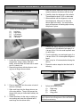
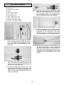
1. Locate the pre-cut aileron hinge slots in both
wing halves. Using a hobby knife (#11
blade), slide the blade into each slot to make
sure it is cleanly cut.
Repeat this process with the ailerons, mak-
ing sure all hinge slots are clean.
2. Place a straight pin into the center of each of
the four CA hinges.
Slide each hinge into the hinge slots on one
of the wing halves. The pin will prevent the
hinges from going in further than halfway into
the wing.
3.
Select the aileron for the wing on which you
are working and insert the exposed half of
each hinge into the aileron slots.
Slide the aileron toward the wing until no gap
remains between the aileron and the wing.
4.
Carefully check the alignment of the aileron.
There should be about 1/32" on both ends.
When satisfied with the alignment, remove
the straight pins, being sure to keep the
aileron tight to the wing. You may wish to
apply a few pieces of masking tape to keep
the pieces in place.
5. Keeping the aileron and wing in position, flex
the aileron to it full deflection and apply 3 or
4 drops of thin CA to the small exposed area
of each hinge.
Turn the assembly over and again apply 3 or
4 drops of thin CA to the exposed hinge sur-
faces.
Allow to dry for 10 minutes before flexing the
aileron.
6.
Repeat the above steps for the other half of
the wing.
JOINING THE WING
1. Collect the following items:
(1) Right wing
(2) Left wing
(1) Wing joiner
NOTE: If the covering on your wing has loosened in
transit, refer to the covering section of the INTRODUC-
TION before continuing.

6
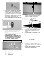
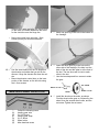
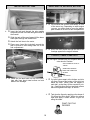
1. Holding the wing joiner with the angle cut
facing up, insert them into the joiner pockets
in both wing halves. The joiner should fit eas-
ily in the pockets and the wing halves should
meet in the middle, with the wing dihedral
forming a broad "V".
2.
Working on a protected surface, and with a
paper towel handy for cleaning fingers,
THOROUGHLY mix 1-2 large (soup) spoons
each from bottle A and bottle B of Epoxy.
(Use equal amount of each part and mix with
a stick in a plastic or paper cup, or on a
sheet of waxed paper.)
Spread epoxy on the joiner on all sides.
Put additional epoxy in the joiner pockets
and in the dowel hole and spread a thin
layer of epoxy along one side of the
entire center joint area. Immediately pro-
ceed to the next step.
3.
Working rapidly, so that the epoxy does
not set before you are finished, slide the
laminated wing joiner into one wing pock-
et.
Place additional tape at several locations
across the center seam of the wing, so that
the halves stay firmly together while the
epoxy sets.
Fit the wing on the fuselage and install the
wing bolts to make sure the dowels on the
front and the wing bolts at the rear align.
AILERON SERVO INSTALLATION
The following pictures may not exactly match the hard-
ware you are using. Always check the radio manufac-
turer's instructions when installing radio equipment.
1. Collect the following items:
(1) Wing
(2) Servos with rubber grommets installed
(8) Servo Mounting Screw (supplied with radio)
(2) servo extensions 12”
2. Plug the servo extension wire into the servo.
There is a string provided to pull the wire
through the wing, it is inside the servo cut
out.
IMPORTANT! To ensure that any connections located
inside the wing will not come loose, when the wires are
pulled, and during flying, always tape them securely
together with electrical tape.
4. With masking tape, tape the wing halves
together at the trailing edge and close to the
leading edge, as shown. This will help keep
the wing from twisting.

Aileron
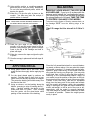
AILERON CONTROL HORN INSTALLATION
1. Collect the following items
(2) Large control horn with back plate
(4) 3/4" screw
(2) Metal clevis
(2) 10” threaded rod
(2) Swivel keepers
2. With the aileron servo arm in place, make a
mark at a 90º degree angle to the trailing
edge and in line with the servo arm.
1.5mm x 20mm
MACHINE SCREWS
METAL CLEVIS
CONTROL
HORN
PLACE CONTROL HORN AT HINGE LINE
Bottom of wing
Wing is upside
down in this view
3. Position the control horn so that the clevis
holes are right next to the hinge line, as
shown.
4.
Using a 3/32" drill bit, make a hole in each
screw location.
Mount the control horn with the 1.5mm x
20mm machine screws.
5. Thread the 10" rod onto the metal clevis.
Make sure the rod shows in the center of the
metal clevis.
Place the metal clevis in the second hole
from the top on the control horn.
7
3. Gently pull the string out of the aileron servo
hole and tie it or tape it to the servo wire.
From the bottom of the wing remove the cov-
ering over the hole that is next to the center
rib.
Pull the servo wire towards the center of the
wing using the string inside the wing.
When the servo plug exits the wing then tape
the plug to the bottom of the wing.
4. Slide the servo into the servo hole in the
wing with the out put arm towards the
aileron.
Using the screws that come with your radio,
mount the servo into the wing.
Repeat these steps for the other half of the
wing, so that both servo extensions are exit-
ing the holes in the center of the wing and
the servos are installed in the wing.

Mark wire
STAB & ELEVATOR INSTALLATION
1. Collect the following parts:
(1) Stabilizer
(2) Elevator
(1) Wing/fuse assembly
(6) Jet hinges
(1) Fin and Rudder
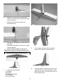
2. Insert the fin in the slot in the top of the stab.
3. Use a marker and draw a line around the
base of the fin where it enters the stab.
4. Using the mark as a guide, remove the cover-
ing inside the line. Use a sharp knife or razor
blade and cut about 1/8” inside the line so no
bare wood will show.
6. Make sure the aileron is in neutral (level)
position, mark where the wire meets the hole
on the servo arm.
Remove the wire and cut it about 1/2"
beyond the mark.
7. Bend the wire 90 degrees up at the mark you
just made.
Slide the swivel keeper over the wire and clip
onto the pushrod.
Slide the silicone keeper over the clevis.
Repeat these steps for the other aileron servo.
8

9
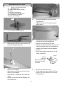
7. Remove the covering inside the line you drew
on the stab also.
5. Epoxy the fin to the stab making sure it is
perpendicular.
6. Place the stab on the fuselage with the fin in
the notch on top and center the stab at the
rear of the fuselage. Mark the bottom of the
stab next to the fuselage.
10. Check the alignment of the stab-fin with the
wing and make sure it is parallel. Use mask-
ing tape to hold the structure in place till the
epoxy set.
8. Remove the covering on the stab saddle of
the fuselage so the stab will glue to bare
wood.
9. Bolt the wing in place and epoxy the stab-fin
structure to the fuselage.
Remove covewring
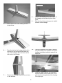
11. Install the rudder using the CA hinges and
mark the location on the rudder horn in line
with the slot on the right side of the fuselage.
Do not glue yet.

10
12. Remove the rudder and align the control horn
on the mark you made. Make sure the holes
for the clevis are over the hinge line.
Mount the control horn using the 1.5mm
screws just as you did on the ailerons.
13. Use the same method for the CA hinges on
the elevator and rudder that you did on the
ailerons. Hinge the elevator first then the rud-
der.
Mount the elevator control horn on the inner
portion of the elevator on the left side using
the 1.5mm screws.
MAIN GEAR & WHEEL INSTALLATION
1. Collect the following items:
(2) Landing gear wire
(4) 2 x 5/16"screw
(2 Landing gear strap
(3) 2-1/2" wheel
(4) Wheel collar
(4) Allen head set screw
3. Insert the other gear leg in the hole on the
other side of the fuselage. One hole is at the
back of the slot and the other is at the front of
the slot. The two wires will lie next to each
other in the slot.
Use the two straps and four screws to retain
the gear.
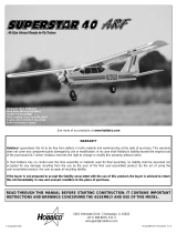
4. Install the wheels on the axles, as shown.
First the wheel collar goes on, followed by the
wheel, then the second wheel collar, and the
set screw. Tighten the set screw.
AXLE
WHEEL
SET SCREW
WHEEL COLLAR
WHEEL COLLAR
2. Insert one gear leg in the hole in the bottom of
the fuselage.

11
NOSEGEAR INSTALLATION
1. COLLECT THE FOLLOWING PARTS
(1) Nosegear strut
(3) Wheel Collars and set screws
(1) Wheel
(1) Nosegear steering arm
(1) 1.5mm x 43 cm wire and tube
(1) EZ connector and screw
(1) Nylon Swivel Keeper
Cut
2. Cut one side off the steering arm.
3. Slide a wheel collar with a set screw onto the
top of the nosegear gear strut.
4. Insert the nosegear strut thru the hole on the
bottom of the fuselage.
Adjust the strut so that the coil is just off the
bottom of the fuselage.
When satisfied, tighten the wheel collar set
screw.
Holding the strut up inside the fuselage, turn
the fuselage over.
5. Slide the steering arm on the top of the
nosegear strut.
Tighten the screw in the steering arm as
shown above.
6. slide the push rod tube through the former
and into the fuel tank compartment.
Insert the 1.5mm wire into the tube.
Make a 1/2” bend in the end of the wire and
insert it through the hole in the steering arm.
Install a swivel keeper over the nosegear
pushrod.
Mount the nosegear wheel just as you did
earlier on the wing.
Pushrod
Connector
Broken View Through
Servo Wheel To Show
Installation
7. Remove the rudder servo arm.
On the rudder servo arm install the EZ con-
nector in the servo hole next to the center
mounting screw.
Nut
Screw

12
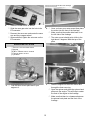
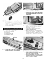
ENGINE INSTALLATION
1. C
OLLECT THE FOLLOWING PARTS
(1)
ENGINE
(4) #6
X 3/4SHEET METAL SCREWS
(1)
MOTOR MOUNT PLATES
(1) SPINNER
2. Find the Motor mount plate and fit your
engine to it.
2. Once you have your motor mount then place
the mount into the front of the fuselage.
Make sure that the smaller side beam is on
the left side of the fuselage.
The motor mount should point a little to the
right about 2 degrees. Mark the top of the
plate.
Left side of the fuselage
Gap
3. Slide the engine into the motor mount and
through the front nose ring.
Open the spinner and place the spinner back
plate onto the engine. This will help to center
the front of the engine to the fuselage
Make sure that there is a clearance between
the spinner back plate and the front of the
fuselage .
8. Install the rudder servo as shown.
Slide the nose gear wire into the hole in the
EZ connector.
Remount the servo arm and center the servo
arm and the nosegear wheel.
When satisified, tighten the set screw on the
EZ connector.

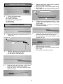
4. Mark the location of the engine mounting
holes.
Also at this time mark the location of where
the throttle pushrod should exit the firewall.
Remove the engine and the motor mount
plate.
5. Drill the engine mounting holes in the plate.
6. Drill the hole for the engine throttle pushrod.
7. Install the motor on the plate using the 4mm
blind nuts and bolts.
8. Remove the motor and put the motor plate in
the opening and mark the location of the blind
nuts.
9. Mark the area of the beams that will be under
the blind nuts and remove enough material to
allow the plate to sit flush on the beams.
13

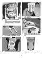
4. Make a 1/4” bend at the end of the throttle
pushrod and connect the push rod to the
throttle arm on the motor.
Slide a swivel keeper in place over the
pushrod and snap in place.
Move the throttle open and close to make
sure you have clearance. If you do not have
enough clearance then cut away some of the
fuselage sides to make enough clearance.
Hole
1. C
OLLECT THE FOLLOWING PARTS
(1) 1.5MM X 40CM PUSHROD
(1) NYLON TUBE
(1)
PUSHROD CONNECTOR
(1) NYLON SWIVEL KEEPER
THROTTLE PUSH ROD INSTALLATION
2. You will need to drill a hole for the throttle rod
through the number 2 and 3 bulkheads.
drill hole
5. Install the throttle servo as shown.
Install the servo connector on the servo out-
put arm as you did for the rudder.
Adjust you throttle arm on the motor to open
and set your servo to fully open. Tighten the
screw on the servo connector.
10. Remount the motor to the plate. If you wish to
have a break away motor mount you can use
four #6 X 3/4” sheet metal screws (not includ-
ed) and screw the plate to the beams, if not,
epoxy the plate in place.
3. Slide the throttle pushrod tubing into the hole
in the firewall that you drilled earlier.
Push the tube through the fuel tank compart-
ment and through the small hole on the side
of the former.
14

15
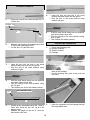
PUSH ROD INSTALLATION
1. Collect the following parts
(2) 19” Wood dowels
(2) 1.5mm x 25cm wire
(2) 1.5mm x 25cm threaded wire
(2) Metal clevis
(4) shrink tubing
ELEVATOR PUSHROD
2. Remove the metal clevis from the end of a 1.5
x 25cm wire.
Threaded end
10”
1/2”
3. Measure, starting from the threaded end, back
10” and make a 90 degree bend.
Cut the wire 1/2” past the bend.
4. Insert the wire into the hole in the wood
pushrod and push down into the groove.
Glue the wire to the wood pushrod using
medium CA glue.
5. Slide the heat shrink tubing over the pushrod
and shrink using a blow drier.
Glue the tubing to the wood pushrod using
thin CA glue.
This finishes one end of the elevator pushrod.
1/2”
7”
NON THREADED WIRE
6. Starting at the non-threaded end of the 1.5mm
x 25cm wire, bend the last 1/2” up at a 90
degree angle.
Measure the length of the wire 7” from the
bend and cut the wire.
7. Insert the wire into the hole in the wood
pushrod and push down into the groove.
Glue the wire to the wood pushrod using
medium CA glue.
8. Slide the heat shrink tubing over the pushrod
and shrink using a blow drier.
Glue the tubing to the wood pushrod using
thin CA glue.
This finishes the elevator pushrod.

16
RUDDER PUSHROD
1. Remove the metal clevis from the end of a 1.5
x 25cm wire.
Threaded end
8”
1/2”
2. Measure, starting from the threaded end, back
8” and make a 90 degree bend.
Cut the wire 1/2” past the bend.
3. Insert the wire into the hole in the wood
pushrod and push down into the groove.
Glue the wire to the wood pushrod using
medium CA glue.
4. Slide the heat shrink tubing over the pushrod
and shrink using a blow drier.
Glue the tubing to the wood pushrod using
thin CA glue.
This finishes one end of the rudder pushrod.
1/2”
6”
NON THREADED WIRE
5. Starting at the unthreaded end of the 1.5mm x
25cm wire, bend the last 3/8” up at a 90
degree angle.
Measure the length of the wire 6” from the
bend and cut the wire.
6. Insert the wire into the hole in the wood
pushrod and push down into the groove.
Glue the wire to the wood pushrod using
medium CA glue.
8. Slide the heat shrink tubing over the pushrod
and shrink using a blow drier.
Glue the tubing to the wood pushrod using
thin CA glue.
This finishes the rudder pushrod.
INSTALLING PUSHRODS
1. Collect the following parts
(1) Elevator Pushrod
(1) Rudder Pushrod
(1) Fuselage
2. Find the hole under the stabilizer on both
sides of the fuselage.
Cut the covering over each of the push rod
exit holes.
3. Insert the pushrods into the fuselage through
the wing saddle area.

17
5. Tape the rudder so that it stays in the neutral
position.
Align the servo arm so that it is sitting at 90
degrees to the servo.
Mark the location where the pushrod wire
meets the outer hole of the servo arm.
6. Bend the wire up 90 degrees at that mark.
Slide the swivel keeper over the end of the
pushrod and snap to the wire.
7. Repeat steps 1 thru 4 for the elevator servo.
3. Bring the elevator pushrod out the right side
and the rudder pushrod out the left side.
4. Put the clevis and the silicone keeper on the
pushrod end and connect to the control horn.
Repeat on the other side for the rudder.
8 Finished pushrods.

18
1. GATHER THE FOLLOWING ITEMS
(1) FUEL TANK
(1) RUBBER TANK STOPPER
(1) CLUNK
(1) 3MM X 25MM SCREW
(1) CAP WASHER LARGE
(1) CAP WASHER SMALL
(1) 3MM X
40MM BRASS TUBE
(1) 3MM X 60MM BRASS TUBE
(1) SILICONE TUBE 4
MM X 80MM
(2)
SILICONE TUBE 5MM X 165MM
2. Insert the 3mm screw through the center
hole in the large washer, through the center
hole in the rubber washer against the large
side, and screw the small washer on the
back side.
FUEL TANK ASSEMBLY
3. Insert the brass tubes through two of the
holes. They should be arranged so as the long
one will be on the right side of the plane and
the short one on the left side.
The tubes should extend out the front of the
cap 5/8”. Bend the long tube up at about a 20
degree angle. This should be adjusted so the
end of the tube almost touches the top of the
tank when installed.
4, Install the 4mm silicone tube to the short
brass tube and install the clunk to the other
end of the silicone tube. This is the fuel pick-
up and must be free to “flop” around in the
tank so it can pick up fuel in any attitude.
5. Install the assembly into the tank so the vent
tube is turned up to the top of the tank and is
positioned on the right side of the tank.
Tighten the screw to expand the rubber cap.
Don’t over tighten or you could split the tank.
6. Attach the two pieces of 5mm tubing to the
two tank outlets. Make a note of which one
you attach to which tube. The short brass with
the clunk is the fuel pickup and must go to the
carburetor. The long brass tube is the vent
and should go to the pressure outlet on the
muffler.

19
INSTALLING FUEL TANK
1. Insert the fuel tank through the wing saddle
area and feed the fuel lines through the hole in
the firewall.
Slide the tank all the way forward till the brass
tubes pass through the firewall hole.
Attach the fuel lines to the motor.
Place some foam (Not included) around the
tank to prevent it from sliding back out of the
fuel compartment.
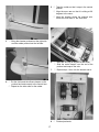
1. install the fuel tank hatch on top of the fuse-
lage with 2mm sheet metal screws on both
sides of the fuselage.
RADIO SWITCH, RECEIVER, BATTERY
1. We mounted the receiver and battery in front
of the servo tray. Depending on what engine
you use, you might need to move the battery
pack forward in to the fuel tank compartment.
2. Mount the radio switch through the side of the
fuselage opposite the engine exhaust.
COCKPIT, CANOPY AND PILOT
The pilot figure included with your airplane adds an
extra touch of realism.
APPLY DABS OF GLUE AT
JOINTS
WHEN DRY, REMOVE
TAPE AND COMPLETE
GLUING
1. Cut pilot halves apart at the bottom and trim
off scrap. Remove the bottom of the pilot just
below his neck. Gently sand the edges of
each half, so that they will be smooth for join-
ing. Carefully align the front and back pieces
and hold together with tape, as shown.
1. Tack glue the figure by applying a few drops of
CA glue at key joint areas. When dry, remove
tape and apply a small amount of glue all
along the seam.
PAINT PILOT AS
DESIRED
Cut line

20
Using artist's acrylics or modeling enamels,
paint the pilot to suit your fancy. WARNING:
Do not use lacquer-based paints, which will
destroy the plastic.
When dry, CA glue the pilot in place on the
cockpit. You also may paint the cockpit, if
added realism is desired.
HINT: WHEN PAINTING THE PILOT'S FACE, LEAVE THE EYES
WHITE. LATER, WHEN THE FACE HAS DRIED, CAREFULLY ADD
EYE DETAILS WITH A FINE BUSH OR TOOTHPICK.
2. Sand the glue edge of the cockpit insert
smooth, try to get the cockpit insert as flat as
possible. Using canopy glue, glue the cockpit
insert to the top of the fuselage and hold in
place with tape.
When dry, remove the tape and glue the pilot
in place.
Glue the canopy in place and hold with tape till
dry.
APPLYING DECAL
1. Using glass cleaner and a soft cloth, clean
model surface thoroughly before applying the
decal.
Cut the decal sheets apart in sections, as
needed. Fold the decal in half, front to rear.
Open at the fold and lay the decal out straight.
The protective backing will bubble away from
the decal at the fold.
Using a scissors, cut the backing along the
bubble, removing a strip of backing about 1"
wide. Carefully position the decal on the
model and stick it in place. Then, working
from the center, rub the decal down while
peeling off the remainder of the backing.
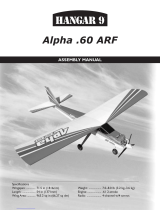
BALANCING
IMPORTANT: NEVER NEGLECT THIS STEP WITH
ANY AIRPLANE. If you try to fly a plane with the
balance point behind the recommended range,
you run the risk of having an unstable aircraft and
the strong likelihood of a crash. TAKE THE TIME
TO PROPERLY BALANCE YOUR MODEL!
To determine the Center of Gravity, measure back on
the fuselage
3-1/2" from the leading edge of the
wing.
The C.G. range for this aircraft is 3-1/4 to 3-
3/4".
Place the fully assembled aircraft on a model balanc-
ing stand, as shown above. You can make this simple
set-up with a couple of ¼" dowels with rounded tops,
spaced 5" apart. Alternatively, lift the model under the
wing near the fuse by your finger tips. (You may wish
to get help from a friend if using the latter method.)
Referring to the recommended balance range for
your model, move the position of the plane on the bal-
ance stand until the model is level or the nose slight-
ly down. If the is tail heavy, shift the R/C equipment
away from the heavy end of the model and recheck
until the model will balance within the acceptable
range. If shifting the R/C gear still doesn't balance the
model, add weight to the far end of the nose or tail,
respectively, until the model is correctly balanced.
The least weight is needed when added as far back
or forward as possible. Fasten the weight perma-
nently in place.
Page is loading ...
-
 1
1
-
 2
2
-
 3
3
-
 4
4
-
 5
5
-
 6
6
-
 7
7
-
 8
8
-
 9
9
-
 10
10
-
 11
11
-
 12
12
-
 13
13
-
 14
14
-
 15
15
-
 16
16
-
 17
17
-
 18
18
-
 19
19
-
 20
20
-
 21
21


Carl Goldberg GPMA1967 Owner's manual
- Category
- Toys & accessories
- Type
- Owner's manual
- This manual is also suitable for
Ask a question and I''ll find the answer in the document
Finding information in a document is now easier with AI
Related papers
-
Carl Goldberg Products GBGA0053 Owner's manual
-
-
Carl Goldberg GBGA1064 Owner's manual
-
-
-
-
-
-
-
Other documents
-
 Hangar 9 Easy Fly 40 User manual
-
 Richmond HORNET 40-52 ARF ECS Assembly & Operation Manual
-
 Hobbico Husky ARF User manual
-
Tower Hobbies Trainer 40 ARF User manual
-
 Hobbico Superstar 40 ARF User manual
-
 Hangar 9 Alpha.60 ARF Assembly Manual
-
AeroWorks BD-5B ELECTRIC ARF Assembly Manual
-
Horizon Hobby Ultra Stick Lite Assembly Manual
-
 Hobbico avistar 40 User manual
-
 Irvine Tutor 40 II User manual


