Page is loading ...

AIR CONDITIONERS CITY MULTI
Models PURY-80TMU, 100TMU
PURY-80TMU-A, 100TMU-A
CMB-104, 105, 106, 108, 1010, 1013, 1016NU-F
Service Handbook

–1–
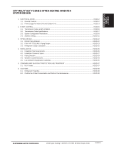
Contents
1PRECAUTIONS FOR DEVICES .............................................................. 3
[1] Storage of Piping Material ................................................................. 3
[2] Brazing .............................................................................................. 4
[3] Airtightness Test ................................................................................ 5
[4] Vacuuming ........................................................................................ 5
2COMPONENT OF EQUIPMENT ............................................................. 6
[1] Appearance of Components ............................................................. 6
[2] Refrigerant Circuit Diagram and Thermal Sensor ........................... 13
[3] Electrical Wiring Diagram ................................................................ 14
[4] Standard Operation Data ................................................................ 18
[5] Function of Dip SW and Rotary SW ................................................ 20
3TEST RUN ............................................................................................. 23
[1] Before Test Run .............................................................................. 23
[2] Test Run Method ............................................................................. 27
4GROUPING REGISTRATION OF INDOOR UNITS WITH REMOTE
CONTROLLER ....................................................................................... 28
5CONTROL .............................................................................................. 34
[1] Control of Outdoor Unit ................................................................... 34
[2] Control of BC Controller .................................................................. 37
[3] Operation Flow Chart ...................................................................... 38
[4] List of Major Component Functions ................................................ 44
[5] Resistance of Temperature Sensor ................................................. 47
6REFRIGERANT AMOUNT ADJUSTMENT ............................................ 48
[1] Refrigerant Amount and Operating Characteristics ........................ 48
[2] Adjustment and Judgement of Refrigerant Amount ........................ 48
7TROUBLESHOOTING ........................................................................... 54
[1] Principal Parts ................................................................................. 54
[2] BC Controller Disassembly Procedure ........................................... 80
[3] Self-diagnosis and Countermeasures Depending on the Check
Code Displayed ............................................................................... 86
[4] LED Monitor Display ..................................................................... 108
8PREPARATION, REPAIRS AND REFRIGERANT REFILLING WHEN
REPAIRING LEAKS ............................................................................. 118
[1] Location of leaks: Extension piping or indoor units (when cooling) 118
[2] Location of leaks: Outdoor unit (Cooling mode) ............................. 118
[3] Location of leaks:
Extension piping or indoor units (Heating mode)
119
[4] Location of leaks: Outdoor unit (when heating) ............................. 119

–2–
Safety precautions
Before installation and electric work
Before installing the unit, make sure you read all
the “Safety precautions”.
The “Safety precautions” provide very important
points regarding safety. Make sure you follow
them.
This equipment may not be applicable to
EN61000-3-2: 1995 and EN61000-3-3: 1995.
This equipment may have an adverse effect on
equipment on the same electrical supply system.
Please report to or take consent by the supply.
authority before connection to the system.
Symbols used in the text
Warning:
Describes precautions that should be observed to
prevent danger of injury or death to the user.
Caution:
Describes precautions that should be observed to
prevent damage to the unit.
Symbols used in the illustrations
: Indicates an action that must be avoided.
: Indicates that important instructions must be followed.
: Indicates a part which must be grounded.
: Beware of electric shock (This symbol is displayed on the
main unit label.) <Color: Yellow>
Warning:
Carefully read the labels affixed to the main unit.
Warning:
• Use the specified cables for wiring. Make the connections
securely so that the outside force of the cable is not
applied to the terminals.
- Inadequate connection and fastening may generate heat and
cause a fire.
• Have all electric work done by a licensed electrician
according to “Electric Facility Engineering Standard” and
“Interior Wire Regulations”and the instructions given in
this manual and always use a special circuit.
- If the power source capacity is inadequate or electric work is
performed improperly, electric shock and fire may result.
• Securely install the cover of control box and the panel.
- If the cover and panel are not installed properly, dust or water
may enter the outdoor unit and fire or electric shock may
result.
• After completing service work, make sure that refrigerant
gas is not leaking.
- If the refrigerant gas leaks and is exposed to a fan heater,
stove, oven, or other heat source, it may generate noxious
gases.
• Do not reconstruct or change the settings of the protection
devices.
- If the pressure switch, thermal switch, or other protection
device is shorted and operated forcibly, or parts other than
those specified by Mitsubishi Electric are used, fire or
explosion may result.
*
▲
▲
▲▲▲

–3–
[1] Storage of Piping Material
(1) Storage location
Store the pipes to be used indoors. (Warehouse at site or owner’s warehouse)
Storing them outdoors may cause dirt, waste, or water to infiltrate.
(2) Pipe sealing before storage
Both ends of the pipes should be sealed until immediately before brazing.
Wrap elbows and T’s in plastic bags for storage.
11
11
1PRECAUTIONS FOR DEVICES

–4–
[2] Brazing
No changes from the conventional method, but special care is required so that foreign matter (ie. oxide scale, water, dirt,
etc.) does not enter the refrigerant circuit.
Example : Inner state of brazed section
When non-oxide brazing was not used When non-oxide brazing was used
Items to be strictly observed :
1. Do not conduct refrigerant piping work outdoors on a rainy day.
2. Apply non-oxide brazing.
3. Use a brazing material (Bcup-3) which requires no flux when brazing between copper pipes or between a copper pipe
and copper coupling.
4. If installed refrigerant pipes are not immediately connected to the equipment, then braze and seal both ends of them.
Reasons :
1. A flux generally contains chlorine. A residual flux in the refrigerant circuit may generate sludge.
Note :
• Commercially available antioxidants may have adverse effects on the equipment due to its residue, etc. When
applying non-oxide brazing, use oxygen free nitrogen (OFN).

–5–
[3] Airtightness Test
Items to be strictly observed :
1. Pressurize the equipment with nitrogen up to the design pressure and then judge the equipment’s airtightness, taking
temperature variations into account.
Reasons :
1. Use of oxygen as the pressurized gas may cause an explosion.
[4] Vacuuming
1. Standard degree of vacuum for the vacuum pump
Use a pump which reaches 65 Pa (0.0094 psi) or below after 5 minutes of operation.
In addition, be sure to use a vacuum pump that has been properly maintained and oiled using the specified oil. If the
vacuum pump is not properly maintained, the degree of vacuum may be too low.
2. Required accuracy of the vacuum gauge
Use a vacuum gauge that can measure up to 650 Pa (0.094 psi). Do not use a general gauge manifold since it cannot
measure a vacuum of 650 Pa (0.094 psi).
3. Evacuating time
• Evacuate the equipment for 1 hour after 650 Pa (0.094 psi) has been reached.
• After envacuating, leave the equipment for 1 hour and make sure that the vacuum is not lost.
4. Operating procedure when the vacuum pump is stopped
In order to prevent a backflow of the vacuum pump oil, open the relief valve on the vacuum pump side or loosen the
charge hose to drawn in air before stopping operation.
The same operating procedure should be used when using a vacuum pump with a check valve.

–6–
SV block Fusible plug Accumulator
CV block Compressor
4-way valve
22
22
2COMPONENT OF EQUIPMENT
[1] Appearance of Components
In case of -A type.

–7–
Controller Box

–8–
MAIN board
CNS1 CNS2 CN40 CN41
CNVCC3
Power Source
for control
1-2 30V
1-3 30V
4-6 12V
5-6 5V
CN51
Indication distance
3-4 Compressor ON/OFF
3-5 Trouble
CNRS3
Serial transmission to
INV board
CN3D
CN3S
LD1
Service LED
SW1
SW2SWU1SWU2SW3SW4CNAC3
Power Output
5 L1
3 L3
1 G
CN20
Power Input
7 L1
5 L2
3 L3
1 G
CNVCC5
Power Source for control(5V)

–9–
INV board
CNDC2
1-3 DC-325V
CN15V2
Power Output
for IPM control
CNVCC4
Power Output (5V)
CNL2
Choke coil
CNVCC2
Power Output
1-2 30V, 1-3 30V
4-6 12V, 5-6 5V
CNDR2
Output to
G/A board
CNCT
CNTH
CNRS2
Serial transmission
to MAIN board
CN52C
Control for 52C
CNFAN
Control for MF1
CNAC2
Power Input
5 L1
3 L3
1 G
SW1

–10–
G/A board
CNIPM1
CN15V1
CNDR1
CNE CNDC1
Power board

–11–
BC controller
CNTR
CN02
M-NET
transmission
CN03
CN12
Power
supply
1 EARTH
3 N
5 L
SW4 SW2 SW1SW5

–12–
RELAY 10 board
RELAY 4 board

–13–
[2] Refrigerant Circuit Diagram and Thermal Sensor

–14–
[3] Electrical Wiring Diagram
1
MC
P
N

–15–
2CMB-104·105·106NU-F
F01
250VAC
6.3A F
CMB-106NU-F ONLY
Circuit
board
(Symbol explanation)
BC controller
(Box internal layout)
T5
T4
T6
T1
T3
T2
1
3
1
1
2
3
1
2
1
2
1
2
3
4
1
123456 123456 1 3 5
2
3
4
5
6
7
8
3
321 21
1
1
1
2
3
4
5
6
7
8
9
10
11
12
13
14
15
16
1
2
3
4
1
2
3
4
1
2
3
4
1
2
3
4
1
2
3
4
1
2
3
4
1
2
3
4
1
2
3
4
1
2
3
4
1
2
3
4
1
2
3
4
1
2
3
4
1
2
3
4
1
2
3
4
1
2
3
4
5
6
7
8
9
10
11
12
13
14
15
16
3
3
5
7
1
3
5
7
1
3
5
7
1
3
5
7
1
3
5
7
1
3
5
7
X2
X1
X30
X4
X3
X31
X6
X5
X32
X8
X7
X33
X10
X9
X34
X12
X11
X35
3
G
2
2
Fuse AC250V 6.3A T
F01
Terminal
T1~6
CN31
CN30
CN29
SV6B
SV6A
SV6C
SV4A
SV4C
SV5B
SV4B
SV5C
SV5A
CN28
CN27
SV1B
SV1A
SV1C
SV2A
SV2C
SV3C
SV2B
SV3B
SV3A
CONT.B
TR
Terminal block
(for Transmission)
TB02
Terminal block
(for power source)
TB01
Solenoid valve
SV1~6A,B,C
Expansion valve
Thermistor sensor
Transformer
Name
Symbol
TR
TH11,12,15,16
LEV1,3
PS1,3 Pressure sensor
CONT.B
Note : 1.TB02 is transmission
terminal block.
Never connect power
line to it.
2.The initial set values
of switch on CONT.B
are as follows.
SW1 : 0
SW2 : 0
TB01
TB02
L1
L2 ~208V-230V 60Hz
⎫
⎬
⎭
⎫
⎬
⎭
Power source
M1
M2
Shield wire
Transmission line
DC 30V
LEV1LEV3
TB01
LEV1
PS3
PS1
TH16
TH15
TH12
TH11
CN07
CN11
CN10
CN13
CN03
CNP3
CNP1
CN02
CONT.B
CN05
CN12
CNTR
CN26
TB02
TR
CMB-105 106NU-F ONLY

–16–
3CMB-108·1010NU-F
⎫
⎬
⎭
⎫
⎬
⎭

–17–
4CMB-1013·1016NU-F
⎫
⎬
⎭
⎫
⎬
⎭

–18–
[4] Standard Operation Data
1Cooling
Outdoor unit
Items PURY-80TMU(-A) PURY-100TMU(-A)
Indoor
Outdoor
Quantity
Quantity in operation
Model
Main pipe
Branch pipe
Total piping length
26.7˚C(80˚F)/19.4˚C(67˚F) 26.7˚C(80˚F)/19.4˚C(67˚F)
35˚C(95˚F) 35˚C(95˚F)
44
44
24 24 20 10 48 16 24 10
5(16.4) 5(16.4)
5(16.4) 5(16.4) 5(16.4) 5(16.4) 5(16.4) 5(16.4) 5(16.4) 5(16.4)
25(82) 25(82)
Hi Hi Hi Hi Hi Hi Hi Hi
10 kg(67 oz) 12 kg(86 oz)
330 460 430 300 410 330 460 300
2000 140 2000 150
235 235
2.03/0.49 1.90/0.39
(294/71) (276/57)
1.92/1.92 1.79/1.79
(279/279) (25/25)
107(225) 110(230)
50(122) 47(117)
7(45) 7(45)
10(50) 10(50)
12(54) 12(54)
75(167) 70(158)
26(79) 30(86)
15(59) 15(59)
Indoor unit fan notch
Refrigerant volume
Compressor volts / Frequency
Outdoor unit
Indoor unit
BC controller (1, 3)
Oil return
High pressure/Low pressure
BC controller liquid/Intermediate
Pressure
DB/WB
Q’ty
–
m
(Ft)
–
kg(oz)
V
V/Hz
A
Pulse
MPa
(psi)
˚C
(˚F)
Condition
Sectional temperature LEV opening
Discharge (TH1)
Heat exchanger outlet (TH5)
Accumulator
Suction (Comp)
Shell bottom (Comp)
LEV inlet
Heat exchanger outlet
Inlet
Outlet
Outdoor
unit
Indoor
unit
Ambient temp.
Indoor unit
Piping
208 230 208 230
134/76 134/76 171/98 171/98
27.4 24.8 35.2 31.8

–19–
2 Heating
Outdoor unit
Items PURY-80TMU(-A) PURY-100TMU(-A)
Indoor
Outdoor
Quantity
Quantity in operation
Model
Main pipe
Branch pipe
Total piping length
21.1˚C(70˚F) 21.1˚C(70˚F)
8.3˚C(47˚F)/6.1˚C(43˚F) 8.3˚C(47˚F)/6.1˚C(43˚F)
44
44
24 24 20 10 48 16 24 10
5(16.4) 5(16.4)
5(16.4) 5(16.4) 5(16.4) 5(16.4) 5(16.4) 5(16.4) 5(16.4) 5(16.4)
25(82) 25(82)
Hi Hi Hi Hi Hi Hi Hi Hi
10 kg(67 oz) 12 kg(86 oz)
600 950 750 400 750 600 950 400
60 700 60 800
150 235
1.81/0.35 1.76/0.36
(263/51) (256/53)
1.72/1.37 1.67/1.37
(249/199) (242/199)
100(212) 95(203)
–2(28) –1(30)
–1(30) –1(30)
–4(25) –2(28)
–1(30) –1(30)
45(113) 40(104)
38(100) 40(104)
80(176) 85(185)
208 230 208 230
149/85 149/85 174/100 174/100
27.5 24.9 35.6 32.2
Indoor unit fan notch
Refrigerant volume
Compressor volts / Frequency
Outdoor unit total current
Indoor unit
BC controller (1, 3)
Oil return
High pressure/Low pressure
BC controller liquid/Intermediate
Pressure
DB/WB
Q’ty
–
m
(Ft)
–
kg(oz)
V
V/Hz
A
Pulse
MPa
(psi)
˚C
(˚F)
Condition
Sectional temperature LEV opening
Discharge (TH1)
Heat exchanger outlet (TH5)
Accumulator
Suction (Comp)
Shell bottom (Comp)
LEV inlet
Heat exchanger outlet
Inlet
Outlet
Outdoor
unit
Indoor
unit
Ambient temp.
Indoor unit
Piping
/