Page is loading ...

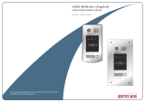
USER MANUAL
Code 50122371 TCODE/CA GB2 EN REV.0 172
Nexa Modular GB2
2-Wire Audio and
Video Door Entry
System
Coded Panel
TECHNOLOGY

G 2 AUDIO AND VIDEO DOOR ENTRY SYSTEM - CODED PANELB
INTRODUCTION
First and foremost we would like to thank you for purchasing this product.
Our commitment to achieving the satisfaction of customers like you is manifested through our ISO-9001 certification
and the manufacture of products like the one you have just purchased.
Its advanced technology and strict quality control will ensure that customers and users enjoy the numerous features
that this device offers. To get the most out of them and ensure proper operation from day one, we recommend that you
read this instruction manual.
CONTENTS
2
SET-UP WARNINGS
-Do not overtighten the screws on the power supply connector.
-Always disconnect the power supply before installing or making modifications to the devices.
-The fitting and handling of these devices must be carried out by .authorised personnel
-The wiring must run at least .40cm away from any other wiring
-Before connecting the device to the mains, check the connections between the door panel, power supply unit,
distributors, camera interface, GSM interface, monitors, telephones and hands-free audio terminals.
-Use the Golmar cable (2x1mm ).RAP-2150 2
-Always follow the instructions contained in this manual.
Introduction................................................................................................................................................................ ..2. .
Contents....................................................................................................................................................................... 2.
Set-up warnings................................................................................................................................ 2................................
Safety precautions........................................................................................................................................... . 3............ .
Characteristics..............................................................................................................................................................3.
System operation.......................................................................................................................................... 3.................
Description of the door panel............................................................................................................................................
.............................................................................................................. .. 4.
Description of the Nexa Modular door panel
............................................................................................................5Description of the EL632/GB2Asound module
................................................................................................................6.Description of the sound module DIP switch
.......................................................................................................................6.Description of the configuration jumper
............................................................................6.Description of the door panel lighting LEDs for “low light conditions”
.......................................................................................................6.Description of the visual signals on the door panel
......................................................................... 7.Description of the vocal synthesis (audible signals on the door panel)
.......................................................................................................... 7 - 8.Selecting the sound module operating mode
....................................................................................................9Description of the TFT EL3422/GB2 screen module
............................................................... 10.Description of the N3401/GB2 and NX3401/GB2 proximity reader module
.......................................................................................................10.Description of the TK3401/GB2 proximity key kit
...................................................... 11.Description of the N3301/GB2 and NX3301/GB2 keypad access control module
................................................................................ 12..Description of the EL3002H/GB2 auditory accessibility module
..........................................................................................................13.Description of the EL3002 illumination module
Installation of the door panel.............................................................................................................................................
..........................................................................................................................................14.
Preparing the cable entry
.........................................................................................................................................14.Fitting the embedding box
.............................................................................................................................. 14.Mounting the electronic modules
................................................................................................................15Fastening the frame to the embedding box
...........................................................................15Connections between the sound, TFT and access control modules
..............................................................................................................................................16.Closing the door panel
Installation of the power supply....................................................................................................................................16.
Installation of the lock release......................................................................................................................................17
Operation of the door panel......................................................................................................................................... 17.
Programming of the door panel........................................................................................................................................
...................................................... 18.
Entering and exiting programming mode/Programming structure and sequence
............................................................................................................................................. 19-25.Programming fields
...................................................................................................................................26.Programming fields summary
.....................................................................................................................................27-29.Managing proximity keys
.................................................................................................................................30-34Managing the apartment list
Wiring diagrams.....................................................................................................................................................35-39.

CHARACTERISTICS
-Audio and video door entry system with simplified wiring (non-polarised 2-wire bus).
-Up to 4 access panels (DP-GB2Adistributor required for more than one access panel) per installation.
-Up to 23 monitors and apartments with a Vesta2 monitor per installation. (Mixed installation with telephones max. 23 elements).
-Up to 18 monitors and apartments with a Vesta7 monitor per installation. (Mixed installation with telephones max. 18 elements).
-Up to 32 telephones and apartments with T562 telephone per installation (audio door entry system installation 'audio only').
-Up to 32 Nhea hands-free audio terminals and apartments per installation (audio door entry system installation 'audio only').
-Up to 4 monitors/telephones per apartment.
-Up to 4 monitors in parallel (installation without distributors) per installation.
-Up to 128 telephones (T562/TNhea) and apartments per installation (EL632/GB2Aset to mode 2 or 6 'audio only', see p 7)..
-Up to 1 telephone per apartment (EL632/GB2Aset to operating mode 2 or 6 'audio only', see page 7).
-Different operating modes configurable on the EL632/GB2Asound module.
-Call confirmation tone.
-Visual signals providing the door panel with auditory accessibility (indicating call process, communication, door open and
channel busy).
-Audible signals providing the door panel with visual accessibility (indicating call in progress, missed call, door open, call
finished and engaged).
-Door opening timeable between 1 and 99 seconds.
-2 outputs for independently activated lock releases.
-Relay 1 output to activate the DC orAC lock releases actuated by relay.
-Relay 2 output to activate the DC orAC lock releases actuated by relay.
-Input for exterior door opening button (Relay 1 output).
-Input for exterior door opening button (Relay 2 output).
-Maximum distance between the power supply and the furthest door panel: 80m with a cross-section of 1mm .
2
-Maximum distance between the power supply and the last distributor: 80m with a cross-section of 1mm .
2
-Maximum distance between the power supply and last telephone (audio only installation without distributors): 80 m with a
cross-section of 1 mm .
2
-Maximum distance between the distributor and monitor/telephone (mixed installation): 40m with a cross-section of 1mm .
2
SAFETY PRECAUTIONS
-Always disconnect the power supply before installing or making modifications to the devices.
-The fitting and handling of these devices must be carried out by .authorised personnel
-The wiring must run at least 40 cm away from any other wiring.
-On the power supply unit:
wDo not overtighten the screws on the connector.
wInstall the power supply unit in a dry protected location free from the risk of dripping or splashing water.
wAvoid locations that are humid, dusty or near heat sources.
wEnsure that the air vents are free from obstruction so that air can circulate freely.
wTo avoid damage, the power supply unit must be firmly secured in place.
wTo prevent electric shock, do not remove the cover or handle the wiring connected to the terminals.
3
G 2 AUDIO AND VIDEO DOOR ENTRY SYSTEM - CODED PANELB
SYSTEM OPERATION
-To make a call, the visitor must select the apartment list or enter the apartment code; an audible sound indicates that
the call is being made and LED will illuminate. If vocal synthesis is enabled, a 'Call is in progress' message appears
indicating that a call is being made. At this moment the apartment's monitor receives the call. To cancel the call, press
the bell button or C.
-In systems with several access doors, the other door panel(s) will be automatically disconnected. If another visitor
tries to call, a number of telephone tones will be heard to indicate that the system is busy and LED will illuminate. If
vocal synthesis is activated, the message 'System is busy, try later' will be indicated on the door panel.
-The call lasts for 40 seconds and, when received, the image appears on the master monitor without the visitor
knowing. To view the image on a slave monitor, this function needs to have been activated on the monitor. If the call is
not answered within 40 seconds, LED will turn off and the channel will be freed.
-To establish communication, press button on any monitor (or pick up the handset of any telephone) in the
apartment and LED on the door panel will illuminate. If the door panel has an EL3002H/GB2 module with
icon displayed on the front, the LED of the EL3002H/GB2 module will illuminate. Make sure that the hearing aid is
15-25 cm away from the door panel to ensure maximum audio quality during communication with the apartment.
-Communication will last for one and a half minutes or until button on the monitor is pressed again (or the handset of
the telephone is replaced). When communication has finished, LEDs and will turn off and the channel will be
freed. If vocal synthesis is activated, a 'Communication is finished' message will indicate that the call is over.
-To open the door, press button during the call or communication processes: one press will activate the lock release
for five seconds and LED will also turn on for five seconds. If vocal synthesis is enabled, a 'Door Opened!' message
will be indicated on the door panel.
-For a description of the functioning and setup of the monitor/telephone, see the monitor's user manual.

DESCRIPTION OF THE DOOR PANEL
Sound modules
EL63 GB2A2/
EL642/GB2A
,2-wire video door entry system with colour television camera.
Door panel component assembly drawing.
Aluminium panel
Electronic modules
Frame moduleEmbedding boxes
Description of the door panel.
Description of the Nexa modular door panel:
Grille module:
N1000/AL
N1110/AL 1P.
N2220/AL 2P.
Clip-on covers: 60xx
Module C. Keypad access:
N3301/GB2
Nexa module separator (x2)
Fixing screws for endpieces (x8)
Side profile (x2)
Side profile Door panel UNE rod
*
Fixing screws for embedding box (x2)
Door panel UNE rod: Enables 2 door panels to be joined.
,2-wire audio door entry system.
5-wire connection cable.
For connecting the
EL632/GB2A module to
the N3401/GB2 module.
EL3422/GB2
TFT screen module
Information module:
N3002/AL.
*
G 2 AUDIO AND VIDEO DOOR ENTRY SYSTEM - CODED PANELB 4
Module C. RFID access:
N3401/GB2
N3301/GB2 keypad
access control module
N3401/GB2 RFID
access control module
12-wire connection cable.
For connecting the
EL632/GB2A module to
the N3422/GB2 module
and the N3301/GB2
module.
3-wire connection cable.
For connecting the
EL632/GB2A module to
the EL3002HGB2 module.

DESCRIPTION OF THE SOUND MODULE
Microphone.
Speaker.
Front.
Sound module buttons (x2).
Terminal strip connector (GB2 Bus).
Socket for connection with the N3301/GB2 access control mod.
Back.
:Positive, negative (12Vdc output for Golmar DC electric lock).
:Contact 'C' for electric lock (Relay 1).
:Contact 'NO' for electric lock (Relay 1).
:Input for exterior door opening button (Relay 1).
:Contact 'NO' for electric lock (Relay 2).
:Contact 'C' for electric lock (Relay 2).
:Input for exterior door opening button (Relay 2).
:Input for exterior call button (button 1).
:Input for exterior call button (button 2).
:Connection BUS (non-polarised).
:Connection BUS (non-polarised).
Button number.
Colour television camera.
+,
C1
NA1
AP ,AP+
NA2
C2
AP+,AP
P1
P2
BUS
BUS
_
Connection terminals:
DIP switch.
Socket for connection with the N3401/GB2 RFID reader mod.
Communication status LEDs.
LEDs (activation in low light conditions).
Micro-SD card slot.
_
_
Do not use (internal use).
Description of the EL632/GB2A sound module:
Socket for connection with the EL3422/GB2 TFT module.
Socket for connection with the EL3002H/GB2 module.
5
G 2 AUDIO AND VIDEO DOOR ENTRY SYSTEM - CODED PANELB
Note: See wiring diagrams for connections (pp. 35-39).

Description of the sound module DIP switch:
1 2 3 4 5 6
ON
+C1
_
1
The DIP switch is located on the left side of the back of the module.
1 2 3 4 5 6
ON
Door panel address:
DIP switches: 1 and 2 OFF (address 1), 1 ON and 2 OFF (address 2), 1 OFF
and 2 ON (address 3), 1 and 2 ON (address 4).
1 2 4 5 6
3
ON
Leave in the OFF position for door panels with double button and set to ON for
door panels with single button.
1 2 3 5 6
4
ON
Leave in the OFF position for use with door panels in houses and set to ON for
use in apartment buildings.
1 2 3 4 6
5
ON
Leave in the ON position to set the door opening time using the configuration
menu. Set to OFF to set the door opening time to 1 second.
1 2 3 4 5 6
ON
Set to ON to configure: (see pp. 7-8)
Sound module operating mode. Leave in the OFF position once configuration is
complete.
Description of the configuration jumper:
1 2 3 4 5 6
ON
+C1
_
1
Important: Do not change the factory default position of the configuration jumper.
Description of the door panel lighting LEDs for low light conditions:
The door panel lighting LEDs will turn on during a call if the door panel lighting at
that moment is low. This enables the user to view the person who has called
from the apartment monitor.
*
( )
*
( ) Factory setting.
Description of the visual signals on the door panel:
Visual signals on the door panel, indicating:
-While calling: LED will illuminate during in call and in communication times.
-During communication: LED will illuminate during the communication process.
-During door release: LED will illuminate during door release.
-End of communication: LEDs and will turn off.
-Calling at one door panel while another door panel is communicating (if there is more than one door panel):
LED will illuminate for 3 seconds.
-While calling and the monitor is in 'Do not disturb' mode: LED will illuminate for 4 seconds.
-While calling (apartment with no monitor or telephone): LED will illuminate for 4 seconds.
*
( )
*
( ) Factory setting.
*
( )
*
( )
*
( )
*
( )
*
( )
6
G 2 AUDIO AND VIDEO DOOR ENTRY SYSTEM - CODED PANELB
DESCRIPTION OF THE SOUND MODULE

7
G 2 AUDIO AND VIDEO DOOR ENTRY SYSTEM - CODED PANELB
Description of the vocal synthesis (audible signals on the door panel):
Audible signals on the door panel.
If vocal synthesis is enabled on the sound module (see page 19 and 21 for configuration), the following voice
messages can be heard on the door panel:
-While calling: 'Call is in progress'.
-During door release: 'Door Opened!'.
-End of communication: 'Communication is finished'.
-Calling at one door panel while another door panel is communicating (if there is more than one door
panel): 'System is busy, try later'.
-While calling and the monitor is in 'Do not disturb' mode: 'Call is in progress'.
-While calling (apartment with no monitor or telephone): 'Resident Unavailable'.
P1
Selecting the sound module operating mode:
To change the operating mode of the sound module, follow these steps:
-Disconnect the door panel's power supply.
-Set DIP 6 on the sound module (see page 6) to OFF.
-Reconnect the door panel's power supply.
-Set DIP 6 to ON.
-Press and hold down button P1 on the sound module for 6 seconds (until the confirmation
tones end).
-Then continue pressing to change the operating mode indicated by the visual alert LEDs of the door panel 'carousel
mode' (see the following operating mode selection table). Once the required operating mode is selected, stop
pressing button P1.
-Finally, set DIP 6 to OFF. Aconfirmation tone will be heard and the visual alert LEDs of the door panel will turn off.
Mode
Function
mode LED LED LED LED
House 1
1
2
( )
1
( )
*
( )
*
Operating modes
ON OFF OFF
ON OFF OFF
OFF ON OFF
OFF
OFF
OFF
3
4
5
ON ON OFF
OFF OFF ON
ON OFF ON
OFF
OFF
OFF
6
7
8
OFF ON ON
ON ON ON
OFF OFF OFF
OFF
OFF
ON
Door
panel
Buttons
Buttons
Buttons
Buttons
Coded
Coded
Coded
Coded
Instal a nl tio
Video panel
Video panel/
Audio panel
Audio panel
Audio panel
Video panel
(Inst. with risers)
Video panel
(Inst. with risers)
Video panel
(Gen. panel inst.)
Video panel
(Gen panel inst.).
Building
(Up to 32 monitors/telephones)
Building 'router'
(Up to 128 monitors/telephones)
Building 'gateway'
(Up to 128 monitors/telephones)
Building 'tel. only'
(Up to 128 telephones)
Building 'tel. only'
(Up to 128 telephones)
Building 'router'
(Up to 256 monitors/telephones)
Building 'gateway'
(Up to 256 monitors/telephones)
Building
(Up to 32 monitors/telephones)
Buttons
Video panel/
Audio panel
( )
2
( )
2
( )
2
( )
2
( )
*
Dip4
OFF
ON
ON
ON
ON
ON
ON
ON
ON
Continued overleaf
( )
*Sound module configured with : house mode and operating mode 1.default setting
( )
1House mode. See the manual enclosed with the corresponding GB2 house kit.
( )
2Building mode 'router'/'gateway'. See the manual enclosed with the RD-GB2/A module.
DESCRIPTION OF THE SOUND MODULE
------ ------ ------ ------
Mode 9 to 12 (no function)

Building mode 'telephones only' (audio panel): Up to 128 telephones/apartments.
Set DIP 4 on the sound module to ON (see page ).6
Building mode 'router': Set DIP 4 on the sound module to ON (see page ).6
-Up to 23 monitors and apartments with a Vesta2 monitor per riser (RD-GB2/A module(s) required).
(Mixed installations with telephones up to 23 elements).
-Up to 18 monitors and apartments with a Vesta7 monitor per riser (RD-GB2/A module(s) required).
(Mixed installations with telephones up to 18 elements).
-Up to 32 telephones and apartments with T562/Nhea telephones per riser (RD-GB2/A module(s) required).
(Audio door entry system installation audio only).
Building mode 'gateway': Set DIP 4 on the sound module to ON (see page ).6
-Up to 23 monitors and apartments with a Vesta2 monitor per interior panel (RD-GB2/A module(s) required).
(Mixed installations with telephones up to 23 elements).
-Up to 18 monitors and apartments with a Vesta7 monitor per interior panel (RD-GB2/A module(s) required).
(Mixed installations with telephones up to 18 elements).
-Up to 32 telephones and apartments with T562/Nhea telephones per interior panel (RD-GB2/A module(s) required).
(Audio door entry system installation audio only).
8
G 2 AUDIO AND VIDEO DOOR ENTRY SYSTEM - CODED PANELB
Selecting the sound module operating mode:
Continued from previous page
Building mode: Set DIP 4 on the sound module to ON (see page ).6
-Up to 23 monitors and apartments with a Vesta2 monitor per installation.
(Mixed installations with telephones up to 23 elements).
-Up to 18 monitors and apartments with a Vesta7 monitor per installation.
(Mixed installations with telephones up to 18 elements).
-Up to 32 telephones and apartments with T562/Nhea telephones per installation.
(Audio door entry system installation audio only).
DESCRIPTION OF THE SOUND MODULE

9
G 2 AUDIO AND VIDEO DOOR ENTRY SYSTEM - CODED PANELB
DESCRIPTION OF THE TFT SCREEN MODULE
Description of the EL3422/GB2 TFT screen module:
Front.
Back.
TFT screen.
Socket for connection with the EL632/GB2A.
Note: See its connections (page 15).

DESCRIPTION OF THE PROXIMITY ACCESS CONTROL MODULE
Description of proximity reader modules N3401/GB2 and NX3401/GB2:
Front.
Back.
Proximity key reader.
Socket for connection with the EL632/GB2A module.
Bell button.
Selection buttons.
10
G 2 AUDIO AND VIDEO DOOR ENTRY SYSTEM - CODED PANELB
Description of the TK3401/GB2 proximity key kit:
MASTER
CARD
ADD MASTER
CARD
DELETE
Management keys for adding/deleting residents keys using the N3401/GB2
module.
MASTER CARD ADD: Key for adding residents proximity keys.
MASTER CARD DELETE: Key for deleting residents proximity keys.
X5 TAGKEY residents access keys (Code 20740427).
Note: To add/delete proximity keys, follow the instructions on pp. 27-29.
Note: See its connections (page 15).

DESCRIPTION OF THE KEYPAD ACCESS CONTROL MODULE
Description of the N3301/GB2 and NX3301/GB2 keypad access control module
Front.
Back.
Numeric keypad.
Bell button.
Cancel button.
Socket for connection with the EL632/GB2.
Terminal strip connector for 22 Vdc output.
:Positive, negative (22 Vdc output maximum 100 mA)+ -
G 2 AUDIO AND VIDEO DOOR ENTRY SYSTEM - CODED PANELB
Connection terminals:
IMPORTANT:
N3301/GB2 and NX3301/GB2 modules are not compatible with the connections of EL610D button
modules.
Note:
See the connections of the N3301/GB2 and NX3301/GB2 modules on page 15.
11

G 2 AUDIO AND VIDEO DOOR ENTRY SYSTEM - CODED PANELB
DESCRIPTION OF THE AUDITORY ACCESSIBILITY MODULE
Description of the EL3002H/GB2 auditory accessibility module:
Front.
Back.
Communication active LED.
Socket for connection with the EL632/GB2A.
Terminal strip connector for 12 Vac power supply.
Connection terminals:
:12 Vac power input (Only required if EL610D modules exist)~ ~
Note: See its connections (page 15).
12

G 2 AUDIO AND VIDEO DOOR ENTRY SYSTEM - CODED PANELB
DESCRIPTION OF THE ILLUMINATION MODULE
Description of the EL3002 illumination module
Front.
Back.
LED illumination panel.
Terminal strip connector for 12 Vac power supply.
Connection terminals:
:12 Vac power input? ?
Note: See its connections (page 15).
NEXA Bus connectors. (Do not connect to GB2 system)
13

INSTALLATION OF THE DOOR PANEL
Pass the cable through the hole made in the embedding box.
Embed the box and ensure that it is level and flush.
Once the embedding box is positioned, remove the
protective stickers from the door panel's fixing holes.
Insert the sound module into the top of the frame module.
Line up the clips on the sound module with the respective housings on the frame module and then press
gently until correctly positioned.
EL632/GB2A
sound module
If TFT module exists, repeat the above process, positioning it below the sound module, as shown in the drawing.
Fitting the embedding box:
Mounting the electronic modules:
Break the flange to allow entry of cables through the bottom
part of the embedding box.
In the case of door panels with more than one embedding box,
break through the side holes and join the embedding boxes
using cable grommets.
Preparing the cable entry:
EL3422/GB2
TFT module
G 2 AUDIO AND VIDEO DOOR ENTRY SYSTEM - CODED PANELB 14

INSTALLATION OF THE DOOR PANEL
Fastening the frame to the embedding box:
Insert the spring hinge which attaches to the product in the
embedding box, as shown in the drawing.
To fasten the frame to the embedding box, insert the spring
hinge into the housings provided for this purpose in the frame,
as shown in the drawing.
The frame can now be tilted horizontally to enable connection and setting of
the sound module, TFT module and access control modules.
Connect the sound module to the different modules as shown in the
following section.
Connections between the sound, TFT and access control modules:
Plug one end of the connection cable attached to the EL3422/GB2
product into the 12-pin socket located on the top right of the sound
module and the other end into the socket located in the centre of the
EL3422/GB2 module. Similarly, connect one end of the connection cable
attached to the N3401/GB2 product to the 5-pin socket located in the left
centre of the sound module and the other end to the socket located on
the bottom right of the N3401/GB2 module. And connect one end of the
connection cable attached to the N3301/GB2 product to the 12-pin
socket located on the bottom right of the sound module and the other end
to the socket located on the bottom right of the N3301/GB2 module.
Once the wiring and configuration work is done, fix the frame to
the embedding box using the screws supplied. Then place the
access control modules into the frame in order to connect the
connection cables between the sound module, access control
modules and TFT as shown in the next section.
G 2 AUDIO AND VIDEO DOOR ENTRY SYSTEM - CODED PANELB
NA2
+AP-
C1 NA1 AP+ C2 AP+ AP- P1 P2 BUSBUS
Relé 2Relé 1
_
12Vdc
Socket for the
EL3002H/GB2 (page 39)
EL3422/GB2
N3401/GB2
N3301/GB2
EL632/GB2A
15

INSTALLATION OF THE DOOR PANEL
Closing the door panel:
Fix the door panel to the embedding box using the screws
supplied.
To complete the fitting of the panel, attach the clip-on covers
by positioning one end and then applying slight pressure to
the other end until they clip into place.
INSTALLATION OF THE POWER SUPPLY UNIT
Installing the FA-GB2/A power supply unit:
Replace the protective cover once the input terminals have been wired.
Please note that current regulations stipulate that the power
supply must be protected by a circuit breaker.
Connect the FA-GB2/A power supply unit to the earth connection.
Mount the DIN rail to the wall with the plugs and screws
supplied.
Then attach the power supply by applying slight
pressure.
The power supply can be installed on a DIN 46277 rail.
.
To remove the power supply unit from the DIN rail, use a flat
screwdriver to lever it off, as shown in the drawing.
The FA-GB2/A model requires 8 elements on the rail.
IMPORTANT: the maximum number of units that can be connected to an FA-GB2/A power supply is 23 VESTA
2 or 18 VESTA7 monitors.
Install the power supply unit in a dry protected location free from the risk of dripping or splashing water.
To prevent electric shock, do not remove the protective cover of the primary or handle the wiring.
The fitting and handling of this device must be carried out by in the absence of electricalauthorised personnel
current.
To avoid damage, the power supply unit must be firmly secured in place.
DIN rail.
DIN rail.
DIN rail.
DIN 46277
DIN rail latch release.
G 2 AUDIO AND VIDEO DOOR ENTRY SYSTEM - CODED PANELB 16

Installing the lock release:
INSTALLATION OF THE LOCK RELEASE
M 4 x 8
3,5 x 25
DIN-7972
DIN-963
IMPORTANT:
-The lock release must be 12V DC orAC (Golmar).
(See page 38 for a.c. lock release and page 35-37 for d.c. lock release).
-The sound module is supplied with two varistors. If connecting an AC lock release to one of the outputs, fit the
varistor supplied directly to the lock release terminals to ensure the device functions correctly.
If the lock release is to be fitted to a metal door, use a Ø3.5mm drill bit and
thread the hole made. For wooden doors, use a Ø3mm drill bit.
G 2 AUDIO AND VIDEO DOOR ENTRY SYSTEM - CODED PANELB
DOOR PANEL OPERATION
Description of door panel operation:
Door panel in standby mode.
With the door panel in standby mode, the following operations can be performed:
Activation of external buttons: Enables activation of the outputs of Relay 1 or Relay 2 by means of the exterior AP
buttons for Relay 1 and Relay 2.
By keypad:
Default administrator code: 1234.
Opening by means of the access code: Enables activation of the output (Relay 1 or Relay 2) associated with the
code. Press the bell button of the N3301/GB2 module, followed by the access code, and confirm with the bell button of
the N3301/GB2 module.
'bell (N3301/GB2)' + 'access code' + 'bell (N3301/GB2)'.
Administrator code: Enables entry into the door panel's programming mode. Press the bell button of the N3301/GB2
module, followed by the administrator code, and confirm with the bell button of the N3301/GB2 module.
'bell (N3301/GB2)' + 'administrator code' + 'bell (N3301/GB2)'.
Calls to monitors and telephones: Enables calls to be made to monitors and/or telephones connected to the same
installation. Press the monitor or telephone code followed by the bell button.
'monitor/telephone code' + 'bell'.
Calls to monitors and telephones through the apartment list: Enables calls to be made to monitors and/or
telephones connected to the same installation. Search for the resident using the arrow keys and press bell to make
the call.
'Search resident using arrows button' + 'bell'.
By proximity:
Opening by means of proximity key: Enables activation of the Relay 1 output associated with the proximity key. Hold
the RFID key near to the reader of the N3401/GB2 module.
Managing proximity keys: Enables the adding/deleting of proximity keys to be managed using the MASTER CARD
keys included in the TK3401/GB2 kit. Use MASTER CARD ADD to add cards or MASTER CARD DELETE to delete
them. It is also possible toActivate/Deactivate the proximity reader and delete all residents keys.
17

PROGRAMMING THE DOOR PANEL
Programming mode entry and exit:
To enter programming mode, press the bell button (N3301/GB2), followed by the administrator code '1234', and finally
confirm by pressing the bell button (N3301/GB2) again.
'bell (N3301/GB2)' + 'administrator code' + 'bell (N3301/GB2)'.
To exit programming mode, press the C button (cancel) once if it is in a programming field or twice if not.
If no button is pressed within 10 seconds, it exits programming mode.
Programming mode entry and exit is confirmed by the emitting of a long and short tone.
1 3 4
Programming mode structure and sequence:
C
0
05
2
Programming of the keypad functions is performed by entering the field or function code, followed by the bell button
(N3301/GB2) and the field value.
Once in programming mode, the programming sequence is as follows:
Enter the code of the field to be programmed: this code is always 2 digits. To confirm, press the bell
button (N3301/GB2) and the keypad will emit a long and then short tone indicating that the field to be
programmed is correct or three short tones if the indicated programming field does not exist.
Enter the value of the field being programmed. Once the value has been entered, press the bell button
(N3301/GB2) and the door panel will emit a long confirmation tone if the information entered is correct
or three short tones if it is not correct.
Note: If no key is pressed within 10 seconds, it will be necessary to enter the programming code and
select the programming field again.
Enter the code of the following field or press the C button (cancel) to exit programming mode.
If wrong information is entered or an access or administrator code is repeated, the door panel will emit three short tones
to indicate that the information is incorrect. If the field code to be programmed was being entered, the programming
code must be re-entered; if the field value was being entered, the field value being configured must be re-entered.
Field Field value
C
or
G 2 AUDIO AND VIDEO DOOR ENTRY SYSTEM - CODED PANELB
2
3
0 1
C C C
03
1
Programming
mode entry
sequence
2
0 5
18

Programming fields:
01
Press the bell button (N3301/GB2) to confirm the selection of the field.
9
0
01
The module is pre-programmed with factory settings except for the activation codes, which are left empty for security
reasons. For system operation tailored to the needs of the user, check the values set in all of the fields. The fields do not
need to be programmed in numerical order.
Field '01': Sets the administrator code.
Bell (N3301/GB2) + administrator code + bell (N3301/GB2).
Enter programming mode:
Step 2: Then press the field number:
Step 1: Press the bell button (N3301/GB2), followed by the administrator code, and confirm with the bell button on
the module (N3301/GB2).
Press '01' to select field '01'.
0 9
Steps: Field + bell (N3301/GB2) + administrator code + bell (N3301/GB2).
Then press the number of the next field to configure or press the C button (cancel)
to exit programming mode.
03 C
or
(Step 1)
(Step 3)
(Step 4)
(Step 5)
Define the new administrator code using the numeric buttons from 0 to 9. The maximum
length of the administrator code is 12 digits.
The factory setting is 1234
PROGRAMMING THE DOOR PANEL
G 2 AUDIO AND VIDEO DOOR ENTRY SYSTEM - CODED PANELB
1 3 4
2
...
...
Continued overleaf
Press the bell button (N3301/GB2) to finish programming the field.
(Step 2)
19

Programming fields:
Continued from previous page
Field '03': Sets relay activation time.
Enables the setting of an activation time for Relay 1 and Relay 2 between 1 and 99 seconds.
PROGRAMMING THE DOOR PANEL
G 2 AUDIO AND VIDEO DOOR ENTRY SYSTEM - CODED PANELB
03 01 99
Steps: Field + bell (N3301/GB2) + activation time + bell (N3301/GB2).
...
Press the bell button (N3301/GB2) to finish programming the field.
99
01
03
Press '03' to select field '03'.
Then press the number of the next field to configure or press the C button (cancel) to
exit programming mode.
04 C
or
(Step 1)
(Step 3)
(Step 4)
(Step 5)
Define the activation time for the relays using the numeric buttons from 0 to 9. The time
entered must have .two digits
The factory setting is 01 seconds
...
Field '04': Sets relay activation mode.
Enables the setting of an activation mode for Relay 1 and Relay 2 between 0 (normally open) or 1 (normally closed).
04 0 1
Steps: Field + bell (N3301/GB2) + activation mode + bell (N3301/GB2).
or
Press the bell button (N3301/GB2) to finish programming the field.
1
0
04
Press '04' to select field '04'.
Then press the number of the next field to configure or press the C button (cancel) to
exit programming mode.
06 C
or
(Step 1)
(Step 3)
(Step 4)
(Step 5)
Define the activation mode for the relays using the numeric buttons 0 or 1.
0: Normally open.
1: Normally closed.
The factory setting is 0
or
Continued overleaf
Press the bell button (N3301/GB2) to confirm the selection of the field.
(Step 2)
Press the bell button (N3301/GB2) to confirm the selection of the field.
(Step 2)
20
/