Page is loading ...

1
BUS
PL
S1+ S2+ S-
1 2
ON
1 2
ON
MIC adjustment
Lock Control Jumper
Camera Code DIP
Main Connect Port
1 2 3
SPK adjustment
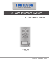
• Fullmetalcoverwithbacklightnameplate
• 4Doorcamerasconnection
• Directlyconnect2separatelocks,unlockmodeandunlocktimecontrolledbyMonitor
Terminal Descriptions
Parts and functions
Name
Camera Lens
Night View LED
Speaker
Nameplate
Call Button
Microphone
90 mm
176 mm
23 mm
Door Camera - DPC-D241-1 User Manual

2
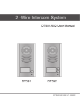
Inner Power 1 Lock Connection
•
Lock Control Jumper:
Toselectthelocktype:whenconnectingaElectromechanicallock,setthejumperin1-2
position;whenconnectingaElectromagneticallock,setthejumperin2-3position.
•
Camera Code DIP:
Total4Cameracanbesupported
1 2
ON
SettotherstCamerawhenmultiCamerasaretobeinstalled;
SettotheCamerawhenthereisonlyoneCameratobeinstalled;
1 2
ON
SettothesecondCamerawhenmultiCamerasaretobeinstalled;
1 2
ON
SettothethirdCamerawhenmultiCamerasaretobeinstalled;
1 2
ON
SettothefourthCamerawhenmultiCamerasaretobeinstalled;
•
Main Connect Port:
Toconnectthebuslineandtheelectroniclocks.
• BUS:Connecttothebusline,nopolarity.
• PL:Externallockpowerinput,connecttothepowerpositive(power+).
• S1+,S2+:Lockpower(+)output,toconnect2locks.
• S-:Lockpower(-)output,connecttothepower(-)inputoflocks(onlywhenusingthecameratopowerthelocks,
ifusingtheexternalpowersupplyforthelocks,theS-willnotbeconnected).
Thestandardinnerpowerlockconnection,usetheCamerapowertosupplythelock,noneedforexternalpower
supply.TheUnlockModeinthemonitorneedtobeset:forPower-to-Unlocktypelock,UnlockModesetto0(in
Monitor,gotoMain-->Setup-->AdvancedSet-->Informationpage,thenpressandholdtheUnlockButtonfor2
secondstoopentheUnlockModesettingpage);forPower-Off-to-Unlocktypelock,UnlockModesetto1.
1 2
ON
1 2 3
to Monitor
-
+
BUS PL S1+ S2+ S- BUS PL S1+ S2+ S-
Jumper position in 1-2
Unlock Mode
0: power-on-to-open
1: power-off-to-open
The lock consumption must not
greater than 12V 500mA.
Electromechanical lock
1 2
ON
1 2 3
to Monitor
-
+
Jumper position in 2-3
The lock consumption must not
greater than 12V 300mA.
Electronmagnetical lock
CALL
UNLOCK
TALK/MON
IN-USE
MENU
Unlock Mode
0: power-on-to-open
1: power-off-to-open
CALL
UNLOCK
TALK/MON
IN-USE
MENU
Connection for Electromechanical lock Connection for Electromagnectical lock

3
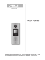
Directlyconnect2electroniclockstothedoorstationandusetheCamerapowertosupplythelocks.Thereare2
separateunlockiconsonMonitorforopeningeachlock.Notethatthe2locksshouldbethesamesafetytype.
Useexternalpowersupplytopowerthelock,inthisway,widerangelockfrom5Vto48Vlockscanbeusedinthe
system.Notethatinthiscase,theLockControlJumperisremovedinbothlocktype.
12
ON
to Monitor
-
+
BUS PL S1+ S2+ S- BUS PL S1+ S2+ S-
-
+
The lock consumption must not
greater than 12V 500mA.
Electromechanical lock
Connection for Electromechanical lock Connection for Electromagnectical lock
lock #2
lock #2
lock #1
lock #1
12
ON
to Monitor
-
+
The lock consumption must not
greater than 12V 300mA.
Electronmagnetical lock
-
+
1 2 3
Jumper position in 1-2
Unlock Mode
0: power-on-to-open
1: power-off-to-open
CALL
UNLOCK
TALK/MON
IN-USE
MENU
1 2 3
Jumper position in 2-3
Unlock Mode
0: power-on-to-open
1: power-off-to-open
CALL
UNLOCK
TALK/MON
IN-USE
MENU
1 2
ON
1 2 3
to Monitor
-
-
+
+
BUS PL S1+ S2+ S- BUS PL S1+ S2+ S-
Jumper removed
The lock consumption must not
greater than 48V 1.5A.
1 2
ON
1 2 3
to Monitor
-
+
Jumper removed
The lock consumption must not
greater than 48V 1.5A.
Electronmagnetical lock
Adaptor
-
+
Unlock Mode
0: power-on-to-open
1: power-off-to-open
CALL
UNLOCK
TALK/MON
IN-USE
MENU
Unlock Mode
0: power-on-to-open
1: power-off-to-open
CALL
UNLOCK
TALK/MON
IN-USE
MENU
Electromechanical lock
Connection for Electromechanical lock Connection for Electromagnectical lock
Inner Power 2 Locks Connection
External Power Connection

4
Mounting Without Rain Cover
Electronic Specications
Mounting With Rain Cover
160-165cm
1
2
1 2 3 4
160-165cm
1
2
1 2 3 4
LockPowersupply: 12Vdc,500mA(suppliedbysystem)
PowerConsumtion: 1Winstandby,12Winworking
Videosignal: 1V
p-p
75
ohmCCIR
NO,COMexchangecontact: Max.48Vdc1.5A
Unlockingtime: 1to9seconds,setbyMonitor
Workingtemperature: -5ºC+45ºC
/