Lots of options, just one ChoiCe.

Lots of options, just one ChoiCe.

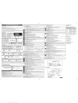
LTR-5 77x35x77mm
Single output on/oFF or piD thermoStat
or humiDiStat
Runs on mains power supply PID with autotuning or ON/OFF control Output on
relay (16A) or SSR piloting Input for PTC, NTC10K or 0÷1V 0.1 / 1°C or 1°F
resolution Refrigerating (dehumidifying) or heating (humidifying) control mode selection
Stand-by button on the front Load start limitation and safety function in the event
of breakage of the sensor Quick setup through ZOT-LTR device Connection to LAE
supervisory systems TAB.
Temperature: Control of small cold stores, refrigerated cabinets and tables, heating systems, heated cupboards, bains-
marie, ovens, laboratory equipment.
Humidity:
Control of greenhouses, seasoning cells, cold rooms, air-conditioned rooms.
applicationS:
How to order examples:
LTR-5CSRE-A (NTC10K input, 1 relay, screw terminals, 230Vac supply, TTL port)
LTR-5ASRU (0÷1V input, 1 relay, screw terminals, 115Vac supply, no serial port)
On request, the LTR-5 is also available with gasket for a better protection between bezel and panel.
(a) -50÷140°C; (b) -40÷110°C; (c) remaining range.
LTR-5 Series
POS.
S= screw terminals; Q= male+female terminals
FUNCTION
Output type
Connectors
Supply
Serial comm.
1 2 3 4 5
1
2
3
4
5
LTR-5 TSRE
Input
DESCRIPTION
T= PTC; C= NTC10K; A= 0÷1V
R = relay; F = SSR drive
D =12Vac/dc; E =230Vac; U =115Vac, 2W
- = no serial port; -A = TTL; -B = RS485
LTR-5T.. LTR-5C..
Functions
Range
Input type
Accuracy
PTC NTC10K
-50÷150
°
C
-60÷300
°
F
±0.3°C(a); ±1.0°C(c)
0÷99.9% r.H.
Resolution 0.1/1°C; °F0.1/1 %
r.H.
Front protectionIP55
LTR-5A..
0÷1V
-40÷125
°
C
-40÷260
°
F
±0.3°C(b); ±1°C(c) ±0.7% r.H.
-B
Panel cut-out 71x29 mm
Ambient temp. -10÷50°C
Wiring diagrams
Applications
Instruction

6 7
230V~
data I/O
OUT1
S.S.R.
+-
4
12V
3
10 11
RS485
LTR-5CSFE-B
6 7
230V ~
data I/O
234
OUT1
16(4)A
10 11
RS485
LTR-5TSRE-B
Wiring diagrams
LTR-5

ApplicAtions
Temperature: Control of small cold stores, refrigerated
cabinets and tables, heating systems, heated cupboards,
bains-marie, ovens, laboratory equipment.
Humidity: Control of greenhouses, seasoning cells, cold
rooms, air-conditioned rooms.

LTR-5 INSTRUCTIONS FOR USE
Thank you for having chosen a LAE electronic product. Before installing the instrument, please read these instructions carefully
to ensure maximum performance and safety.
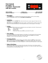
DESCRIPTION INDICATIONS
Thermostat output
Fig.1 — Front panel
Setpoint button. Increase button.
Decrease button. Exit / Stand-by button.
INSTALLATION
Insert the controller through a hole measuring 71x29 mm.
Make sure that electrical connections comply with the paragraph “wiring diagrams”. To reduce the effects of electromagnetic
disturbance, keep the sensor and signal cables well separate from the power wires.
Fix the controller to the panel by means of the suitable clips, by pressingly gently; if fi tted, check that the rubber gasket
adheres to the panel perfectly, in order to prevent debris and moisture infi ltration to the back of the instrument.
Place the probe T1 inside the room in a point that truly represents the temperature of the stored product.
OPERATION
DISPLAY
During normal operation, the display shows either the temperature measured or one of the following indications:
OFF Controller in stand-by E1 In tuning: timeout1 error
OR Probe T1 overrange or failure E2 In tuning: timeout2 error
TUN / 5.4 Controller in autotuning E3 In tuning: overrange error
SETPOINT (display and modifi cation of desired temperature value)
press button
for at least half second, to display the setpoint value.
By keeping button
pressed, use button
or
to set the desired value (adjustment is within the minimum SPL and the
maximum SPH limit).
When button
is released, the new value is stored.
STAND-BY
Button , when pressed for 3 seconds, allows the controller to be put on a standby or output control to be resumed (with
SB=YES only).
CONTROLLER AUTOTUNING IN PID MODE
Before starting
Adjust the setpoint 1SP to the desired value.
Set 1Y=PID.
Make sure that the 1PB value matches the desired control mode (1PB<0 for heating; 1PB>0 for refrigeration).
Start autotuning
Keep buttons
+
pressed for 3 seconds. 1CT blinks on the display.
With +
or
set the cycle time in order to defi ne the dynamic of the process to be controlled.
To start autotuning press
+
or wait for 30 seconds. To abort the autotuning function, press
X
.
During autotuning
During the entire autotuning phase, the display alternates with the actual temperature measured.
In case of power failure, when power is resumed, after the initial autotest phase, the controller resumes the autotuning
function.
To abort the autotuning, without modifying the previous control parameters, keep button
X
pressed for 3 seconds.
After the autotuning has taken place successfully, the controller updates the control parameters and start to control.
Errors
If the autotuning function failed, the display shows an error code:
E1 timeout1 error: the controller could not bring the temperature within the proportional band. Increase 1SP in case of
heating control, vice versa, decrease 1SP in case of refrigerating control and re-start the process.
E2 timeout2 error: the autotuning has not ended within the maximum time allowed (1000 cycle times). Re-start the autotuning
process and set a longer cycle time 1CT.
E3 temperature overrange: check that the error was not caused by a probe malfunction, then decrease 1SP in case of heating
control, vice versa increase 1SP in case of refrigerating control and then re-start the process.
To eliminate the error indication and return to the normal mode, press button
X
.
Control improvement
To reduce overshoot, reduce the integral action reset 1AR.
To increase the response speed of the system, reduce the proportional band 1PB. Caution: doing this makes the system less
stable.
To reduce swings in steady-state temperature, increase the integral action time 1IT; system stability is thus increased,
although its response speed is decreased.
To increase the speed of response to the variations in temperature, increase the derivative action time 1DT. Caution: a high
value makes the system sensitive to small variations and it may be a source of instability.
RECALIBRATION
Have a precision reference thermometer or a calibrator to hand.
Ensure that OS1=0 and SIM=0.
Switch the controller off then on again.
During the auto-test phase, press buttons
X
+
, and keep them pressed till the controller shows 0AD.
With buttons
and
select 0AD or SAD: 0AD allows a calibration of 0, inserting a constant correction over the whole
scale of measurement. SAD allows a calibration of the top part of the measurement scale with a proportional correction
between the calibration point and 0.
Press to display the value and then use
+
or
to make the read value coincide with the value measured by the
reference instrument.
Exit from calibration by pressing button
X
.
CONFIGURATION PARAMETERS
Setup menu is accessed by pressing buttons +
X
for 5 seconds.
With button
or
select the parameter to be modifi ed.
Press button
to display the value.
By keeping button
pressed, use button
or
to set the desired value.
When button
is released, the newly programmed value is stored and the following parameter is displayed.
To exit from the setup, press button
X
or wait for 30 seconds.
PAR RANGE DESCRIPTION
SCL
1°C;
2°C;
°F
Readout scale.
1°C : measuring range -50/-19.9 … 99.9/150°C for LTR-5T
-40/-19.9 … 99.9/125°C for LTR-5C
0.0 … 99.9 %r.H. for LTR-5A
2°C : measuring range -50 … 150°C for LTR-5T
-40 … 125°C for LTR-5C
00 … 99 %r.H. for LTR-5A
°F : measuring range -60 … 300°F for LTR-5T
-40 … 250°F for LTR-5C
Caution: upon changing the SCL value, it is then absolutely necessary to re-configure the parameters relevant to the
absolute and relative temperatures (SPL, SPH, 1SP, 1HY, etc..).
SPL
-50..SPH Minimum limit for 1SP setting
SPH
SPL.150° Maximum limit for 1SP setting
1SP
SPL... SPH Setpoint (value to be maintained in the room).
1Y
HY / PID Control mode.
With 1Y=HY you select control with hysteresis: parameters 1HY and 1CT are used.
With 1Y=PID you select a Proportional-Integral-Derivative control mode: parameters 1PB, 1IT, 1DT, 1AR, 1CT will
be used.
1HY
-19.9…19.9°C Thermostat differential [control with hysteresis].
Set 1HY on a value greater than zero to make the output work in refrigerating mode, vice versa set on a value lower
than zero to make the output work in heating mode. With 1HY=0 the output is always off.
OFF
ON
1SP 1SP+1HY
T[°]
OFF
ON
1SP1SP-1HY
T[°]
Fig. 1a. ON/OFF refrigerating control (1Y=HY, 1HY>0) Fig. 1b. ON/OFF heating control (1Y=HY, 1HY<0)
1PB
-19.9…19.9°C Proportional band [PID control].
Set 1PB on a value greater than zero to make the output work
in refrigerating mode, vice versa set on a value lower than
zero to make the output work in heating mode. With 1PB=0
the output is always off.
With a proportional controller, the temperature is controlled
by varying the time of activation of the output. The nearer the
temperature to set point, the less time of activation. A small
proportional band increases the promptness of response
of the system to temperature variations, but tends to make
it less stable. A purely proportional control stabilises the
temperature within the proportional band but does not cancel
the deviation from the set point.
1IT
0…999s Integral action time [PID control].
The steady-state error is cancelled by inserting an
integral action into the control system. The integral action
time, determines the speed with which the steady-state
temperature is achieved, but a high speed (1IT low) may be
the cause of overshoot and instability in the response. With
1IT= 0 the integral control is disabled.
1DT
0…999s Derivative action time [PID control].
Response overshoot in a system controlled by a Proportional-
Derivative controller may be reduced by inserting a derivative
action in the control. A high derivative action (1DT high)
makes the system very sensitive to small temperature
variations and causes instability. With 1DT=0 the derivative
control is disabled.
1AR
0…100% Reset of integral action time referred to 1PB [PID control].
Decreasing the parameter 1AR reduces the integral control action zone, and consequently the overshoot (see figure
on paragraph 1IT).
1CT
0…255s Cycle time.
In the ON/OFF control (1Y=HY), after the output has switched on or off, it will remain in the new state for a minimum
time of 1CT seconds, regardless of the temperature value.
In the PID control (1Y=PID), the cycle time is the period of time in which the output completes a cycle (Time ON +
Time OFF). The faster the system to be controlled reacts to temperature changes, the smaller the cycle time should
be, in order to obtain a greater temperature stability and less sensitivity to load variations.
1PF
ON / OFF Output state in case of probe failure.
BAU
NON / SBY With BAU=SBY, the stand-by button is enabled.
SIM
0...100 Display slowdown.
OS1
-12.5..12.5°C Probe T1 offset.
ADR
1...255 LTR-5 address for PC communication.
WIRING DIAGRAMS
TECHNICAL DATA
Power supply
LTR-5…D 12Vac/dc±10%, 2W
LTR-5…E 230Vac±10%, 50/60Hz, 2W
LTR-5…U 115Vac±10%, 50/60Hz, 2W
Relay outputs (LTR-5..R..)
LTR-5.SR.. OUT1 16(4)A
LTR-5.QR.. OUT1 12(4)A
SSR drive (LTR-5..F..)
OUT1 15mA 12Vdc
Inputs
LTR-5A…: 0-1V
LTR-5C…: NTC 10KΩ@25°C, part No. LAE SN4...
LTR-5T…: PTC 1000Ω@25°C, part No. LAE ST1…
Measuring Range
LTR-5A…: 0…99%r.H.
LTR-5C…: -40…125°C
LTR-5T…: -50…150°C
Measuring accuracy
LTR-5A…: <±0.7%r.H. in the measuring range
LTR-5C…: <±0.3°C -40…100°C; ±1°C out of that range
LTR-5T…: <±0.3°C -50…140°C; ±1°C out of that range
Operating conditions
-10 … +50°C; 15…80% r.H.
CE (Reference Norms)
EN60730-1; EN60730-2-9;
EN55022 (Class B);
EN50082-1
Front protection
IP55
VIA PADOVA, 25
31046 ODERZO /TV /ITALY
TEL. +39 - 0422 815320
FAX +39 - 0422 814073
www.lae-electronic.com
E-mail: [email protected]
PARTNER VENEZIA • 041 5460713
6 7
OUT1
12(4)A
234
910 11
rH
V
VINV+ V-
TTL
230V~
data I/O
LTR-5AQRE-A
RS485
2346 7
OUT1
16(4)A
10 11
230V~
data I/O
LTR-5TSRE-B
1SP
1PB
Temperature
Overshoot
Steady-state error
Process
temperature
Time
1SP
1PB
Temperature
Overshoot
Process
temperature
Time
1PBx1AR%
integral control
action area
1SP
1PB
Temperature
Overshoot
Process
temperature
Time
RS485
6 7
OUT1
S.S.R.
+-
15mA
4
12V
3
10 11
230V ~
data I/O
LTR-5CSFE-B
ISTR LTR-5 INGL/TED.indd 1ISTR LTR-5 INGL/TED.indd 1 11-12-2007 15:45:2711-12-2007 15:45:27

AC1-5 77x35x77 mm
two channel univerSal controller, on/oFF
or piD
Runs on mains power supply PID with autotuning or ON/OFF control Main
output on 12A relay or for SSR-piloting and auxiliary output on 5A relay Input
for 0÷1V, 0/4÷20mA, PTC/NTC10K, TC J/K or Pt100 0.1 / 1°C or 1°F resolution
Selectable Refrigerating/Heating (Dehumidifying/Humidifying) control Absolute or
relative temperature alarms ON/OFF button on front Load start limitation and
safety operation in case of probe failure Quick programming through ZOT-AC1 key
Connection to LAE TAB supervisory systems
Temperature: Control of small cold stores, refrigerated cabinets and tables, heating systems, heated
cupboards, bains-marie, ovens, laboratory equipment.
Humidity: Control of greenhouses, seasoning cells, cold rooms, air-conditioned rooms.
applicationS:
How to order:
AC1-5TS2RW-A (PTC/NTC10K input, screw terminals, 2 relays, 115÷230Vac supply voltage, TTL port)
AC1-5AS2MD-B (0÷1V input, screw terminals, output 1 on SSR drive, output 2 on relay, 12Vac/dc supply voltage,
RS485 port)
On request, the AC1-5 is also available with gasket for a better protection between bezel and panel.
* = in the version with 12Vac/dc power supply, the maximum voltage on the outputs is 50Vac/dc, in order to ensure
safety insulations.
AC1-5 Series
AC1-5T..
Functions
Range
Input type
Accuracy
PTC
-50÷150°C
-60÷300°F
±0.3°C
NTC10K
-40÷125°C
-40÷260°F
±0.3°C
AC1-5A.. AC1-5I..
0÷1V
Configurable in setup
±3mV
0/4÷20mA
±0.2mA
AC1-5J..
TC “J”
-50÷750°C
-60÷999°F
±3°C
TC “K”
-50÷999°C
-60÷999°F
AC1-5P..
Pt100
-100÷850°C
-150÷999°F
±0.3°C(a);
±1°C(b)
Resolution 1 °C / °F 0.1/10.1 / 1 °C / 1 °F
POS.
S = built-in screw terminals
FUNCTION
Output No.
Connections
Output type
Supply
1 2 3 4 5
1
2
3
4
5
AC1-5
Input
DESCRIPTION
A = 0÷1V; I = 0/4÷20mA; J = TC ‘J’ / ‘K’; P = Pt100; T = PTC/ NTC10K
1 = one; 2 = two
R = relay; M = Out1 on SSR, Out2 on relay
D* = 12Vac/dc; W = 115…230Vac 50/60Hz; 3 W
Serial comm.
6
Nil = no; -A = TTL; -B = RS485
T S 1 R W
6
-B
(a) -50÷150°C; (b) remaining range.
Wiring diagrams
Applications
Instruction

12(4)A
TTL
7(2)A
115...230V˜
OUT1 OUT2
10 11
1 2 3 4 5 6 7
AC1-5TS2RW-A
Wiring diagrams
AC1-5
15mA
RS485
7(2)A
115...230V˜
OUT1 OUT2
109 11
1 2 4 5 6 7
W R W
SSR
-+
12V
AC1-5PS2MW-B

ApplicAtions
Temperature: Control of small cold stores, refrigerated
cabinets and tables, heating systems, heated cupboards,
bains-marie, ovens, laboratory equipment.
Humidity: Control of greenhouses, seasoning cells, cold
rooms, air-conditioned rooms.

Exit from calibration by pressing button ■.
CONFIGURATION PARAMETERS
To get access to the parameter conguration menu, press button ■ + for 5 seconds.
With button ■ or select the parameter to be modied.
Press button ■ to display the value.
By keeping button ■ pressed, use button or to set the desired value.
When button ■ is released, the newly programmed value is stored and the following parameter is displayed.
To exit from the setup, press button ■ or wait for 30 seconds.
PAR RANGE DESCRIPTION
SCL 1°C;
2°C;
°F
Readout scale (see table of input specications)
Caution: upon changing the SCL value, it is then absolutely necessary to recongure the param-
eters relevant to the absolute and relative temperatures (SPL, SPH, 1SP, 1HY etc..)
SPL -50°...SPH Minimum limit for 1SP setting
SPH SPL...150° Maximum limit for 1SP setting.
1SP SPL... SPH Setpoint (value to be maintained in the room).
1CM HY; PID Control mode.
With 1CM=HY you select control with hysteresis: parameters 1HY, 1T0 and 1T1 are used.
With 1CM=PID you select a Proportional-Integral-Derivative control mode: parameters 1PB, 1IT,
1DT, 1AR, 1CT will be used
1CH REF; HEA Refrigerating (REF) or Heating (HEA) control mode.
1CM=HY
1HY 0...19.9° OFF/ON thermostat differential. With 1HY=0 the output is always off.
1T0 0...30min Minimum off time.
After output 1 has been turned off, it remains inactive for 1T0 minutes regardless of the
temperature value measured.
1T1 0...30min Minimum on time. (the following parameter will be 1PF).
After output 1 has been turned on, it remains active for 1T1 minutes regardless of the temperature
value measured.
1CM=PID
1PB 0...19.9° Proportional bandwidth.
Temperature control takes place by changing the
ON time of the output: the closer the temperature
to the setpoint, the less time of activation. A small
proportional band increases the promptness of
response of the system to temperature variations,
but tends to make it less stable. A purely
proportional control stabilises the temperature
within the proportional band but does not cancel
the deviation from setpoint.
With 1PB=0 the output is always off.
1IT 0...999s Integral action time.
The steady-state error is cancelled by inserting an
integral action. The integral action time, determines
the speed with which the steady-state temperature
is achieved, but a high speed (1IT low) may be the
cause of overshoot and instability in the response.
With 1IT=0 the integral control is disabled.
1DT 0...999s Derivative action time.
Response overshoot may be reduced by inserting
a derivative Action. A high derivative action (1DT
high) makes the system very sensitive to small
temperature variations and causes instability. With
1DT=0 the derivative control is disabled.
1AR 0...100% Reset of integral action time referred to 1PB
Decreasing the parameter 1AR reduces the integral control action zone, and consequently the
overshoot (see gure on paragraph 1IT).
1CT 1...255s Cycle time.
It’s the period in which the output ON time changes. The quicker the system to be controlled
reacts to temperature variations, the smaller the cycle time must be, in order to obtain higher
temperature stability and less sensitivity to load variations.
1PF ON/OFF Output state in case of probe failure.
OAU NON;
THR;
AL0;
AL1
AUX output operation.
NON : output disabled (always off). (the next parameter will be ATM)
THR: output programmed for second thermostat control (the next parameter will be 2SM).
AL0: contacts open when an alarm condition occurs (the next parameter will be ATM).
AL1: contacts make when an alarm condition occurs (the next parameter will be ATM).
OAU=THR
2SM ABS;
REL
Setpoint 2 mode.
Channel 2 setpoint may be absolute (2SM=ABS), or a differential relative to setpoint 1 (2SM=REL)
2SM=ABS
2SP SPL...SPH Auxiliary output switchover temperature (the next parameter will be 2CH)
2SM=REL
2DF -19.9...19.9° Temperature differential relative to 1SP. The auxiliary output setpoint is equal to 1SP+2DF
ON/OFF refrigerating control
(1CM=HY, 1CH=REF)
ON/OFF heating control
(1CM=HY, 1CH=HEA)
1SP 1SP+1HY T[°]
ON
OFF
1SP1SP-1HY T[°]
ON
OFF
Time
Temperature
Process
temperature
Overshoot Steady-state error
1PB
1SP
Time
Temperature
Process
temperature
Overshoot
1PB
1PBx1AR%
integral control
action area
1SP
Time
Temperature
Process
temperature
Overshoot
1PB
1SP
2SP 2SP+2HY T[°]
ON
OFF
2SP2SP-2HY T[°]
ON
OFF
ON/OFF control in refrigeration
(2SM=ABS, 2CH=REF)
ON/OFF control in heating
(2SM=ABS, 2CH=HEA)
1SP+2DF
1SP
2DF>0 1SP+2DF+2HY T[°]
ON
OFF
1SP
1SP+2DF
2DF<0
1SP+2DF-2HY T[°]
ON
OFF
ON/OFF control in refrigeration. Setpoint 2
relative to setpoint 1 (OAU=THR, 2CH=REF)
ON/OFF control in heating. Setpoint 2
relative to setpoint 1 (OAU=THR, 2CH=HEA)
TECHNICAL DATA
Power supply
AC1-5…D 12Vac/dc ±10%, 2W
AC1-5...W 110 - 230Vac±10%, 50/60Hz, 2W
Relay outputs (AC1-5..R..)
OUT1 12(4)A
OUT2 7(2)A
SSR drive (AC1-5..M..)
OUT1 15mA 12Vdc
Inputs
see table of input specications
Measurement range
see table of input specications
Measurement accuracy
see table of input specications
Operating conditions
-10 … +50°C; 15%...80% U.R.
CE (Reference Norms)
EN60730-1; EN60730-2-9;
EN55022 (Class B); EN50082-1
Front protection
IP55
VIA PADOVA, 25
31046 ODERZO /TV /ITALY
TEL. +39 - 0422 815320
FAX +39 - 0422 814073
www.lae-electronic.com
E-mail: [email protected]
OAU=THR
2CH REF; HEA Refrigerating control (REF) or heating control mode (HEA) for the auxiliary output.
2HY 0...19.9° Differential of thermostat 2. With 2HY=0 the auxiliary output always remains off.
2T0 0...30min Minimum off time.
After output 2 has been turned off, it remains inactive for 2T0 minutes regardless of the temperature
value measured.
2T1 0...30min Minimum on time.
After output 2 has been turned on, it remains active for 2T1 minutes regardless of the temperature
value measured.
2PF ON/OFF Auxiliary output state in case of probe failure.
ATM NON;
ABS;
REL
Alarm threshold management.
NON: all temperature alarms are inhibited (the following parameter will be SB).
ABS: the values programmed in ALA and AHA represent the real alarm thresholds.
REL: the values programmed in ALR and AHR are alarm differentials referred to 1SP and 1SP+1HY.
ATM=ABS
ALA -50°...AHA Low temperature alarm threshold.
AHA ALA...150° High temperature alarm threshold.
ATM=REL
ALR -12.0...0° Low temperature alarm differential.
With ALR=0 the low temperature alarm is excluded
AHR 0...12.0° High temperature alarm differential.
With AHR=0 the high temperature alarm is excluded
ATD 0...120min Delay before alarm temperature warning.
SB NO/YES Stand-by button enabling.
INP 0mA/4mA,
T1/T2
ST1/SN4
Sensor input selection (see table of input specications).
In the models AC1-5A..., AC1-5J..., AC1-5T... only.
RLO -19.9...RHI Minimum range value (in the models AC1-5A…, AC1-5I… only)
RLO takes the minimum value measured by the transmitter (i.e. the value matching 0V, 0/4mA).
RHI RLO...99.9 Maximum range value (in the models AC1-5A…, AC1-5I… only)
RHI takes the maximum value measured by the transmitter (i.e. the value matching 1V, 20mA)
OS1 -12.5...12.5° Probe T1 offset.
TLD 1...30min Delay for minimum temperature (TLO) and maximum temperature (THI) logging.
SIM 0...100 Display slowdown
ADR 1...255 AC1-5 address for PC communication
INPUT SPECIFICATIONS
MODEL INPUT RANGE [MEASUREMENT ACCURACY]
SCL=1°C SCL=2°C SCL=°F
AC1-5A... 0÷1V RLO÷RHI [< ± 3mV] ---
AC1-5I... INP = 0mA 0÷20mA RLO÷RHI [< ± 0.2mA] ---
INP = 4mA 4÷20mA
AC1-5J... INP=T1 TC “J” --- -50÷750°C [ < ±3°C ] -60÷999°F [ < ±5°F ]
INP=T2 TC “K” --- -50÷999°C [ < ±3°C ]
AC1-5P... PT100 -50/-19.9÷99.9/150°C
[ < ±0.3°C ]
-100÷850°C
[ <±1°C(-50÷850°), ±2°C ]
-150÷999°F
[ <±2°F(-60÷999°), ±4°F]
AC1-5T...
INP=ST1 PTC 1000 Ω
(LAE ST1..)
-50/-19.9 ÷ 99.9/150°C
[<±0.3°C(-30÷130°),±1°C]
-50 ÷ 150°C
[<±0.3°C(-30÷130°), ±1°C]
-60 ÷ 300°F
[< ±0.6°F(-20÷260°),±2°F]
INP=SN4 NTC 10K Ω
(LAE SN4..)
-40/-19.9 ÷ 99.9/125°C
[<±0.3°C(-40÷100°),±1°C]
-40 ÷ 125°C
[<±0.3°C(-40÷100°),±1°C]
-40 ÷ 260°F
[<±0.6°F(-40÷210°), ±2°F]
WIRING DIAGRAMS
1SP
1SP-ALR
T[°]
ON
OFF
1SP+1HY+AHR
1SP1SP-1HY-ALR 1SP+AHR
T[°]
ON
OFF
Temperature alarm with relative thresholds,
refrigerating control (ATM=REL, 1CH=REF) Temperature alarm with relative thresholds,
heating control (ATM=REL, 1CH=HEA).
AC1-5AS2RW-B
data I/O
115... ~230V
OUT2
RS485
7(2)A
OUT1
12(4)A
rH
V
910 11
V
IN
V+ V-
1234
56 7
AC1-5JS2RW-A
data I/O
115... ~230V
OUT2
TTL
7(2)A
OUT1
12(4)A
+-
10 11
1234
56 7
AC1-5PS2MW-B
data I/O
115... ~230V
OUT2
RS485
7(2)A
12
12V
OUT1
15mA
SSR
+
-
WRW
910 11
12456 7
AC1-5TS2RW-A
data I/O
115... ~230V
OUT2
TTL
7(2)A
OUT1
12(4)A
10 11
1234
56 7
DISPLAY
During normal operation, the display shows either the temperature measured or one of the following indications:
OFF Controller in stand-by TUN/xx.x Controller in autotuning
OR Probe T1 overrange or failure E1 In tuning: timeout1 error
HI Room high temperature alarm E2 In tuning: timeout2 error
LO Room low temperature alarm E3 In tuning: overrange error
MENU INFO
The information available in this menu is:
THI Maximum temperature recorded LOC Keypad state lock
TLO Minimum temperature recorded
Access to menu and information displayed.
Press and immediately release button
■.
With button
■ or select the data to be displayed.
Press button
■ to display value.
To exit from the menu, press button
■ or wait for 10 seconds.
Reset of THI, TLO recordings
With button
■ or select the data to be reset.
Display the value with button
■.
While keeping button ■ pressed, use button .
CHANNEL 1 SETPOINT (display and modication of desired temperature value)
Press and release button ■ : the LED L1 blinks, the display shows 1SP for 1 second and then the setpoint associated value.
Press buttons ■ or to set the desired value (adjustment is within the minimum SPL and maximum SPH limit).
To store the new value press button ■ , or wait for 10 seconds.
To go back to normal mode without saving the new value, press ■.
CHANNEL 2 SETPOINT
With the auxiliary output set as thermostat control ( ■OAU=THR), it’s possible to modify setpoint 2 during the normal operation
of the controller.
Press and release button ■ : the LED L2 blinks, the display shows 2SP for 1 second if setpoint 2 is an absolute threshold
(2SM=ABS), alternatively the display shows 2DF, if setpoint 2 is a threshold relative to setpoint 1 (2SM=REL), then the value
associated to the parameter appears.
Press buttons ■ or to set the desired value.
To store the new value press button ■ or wait for 10 seconds.
To go back to normal mode without saving the new value, press ■.
STAND-BY
Button , when pressed for 3 seconds, allows the controller to be put on a standby or output control to be resumed (with SB=YES only).
KEYPAD LOCK
The keypad lock avoids undesired, potentially dangerous operations, which might be attempted when the controllers is operating
in a public place. In the INFO menu, set parameter LOC=YES to inhibit all functions of the buttons. To resume normal operation
of keypad, adjust setting so that LOC=NO.
CONTROLLER AUTOTUNING IN PID MODE
Before starting
In the setup mode (see conguration parameters): set 1CM=PID; make sure that 1CH matches the desired operation mode
(1CH=REF for refrigerating control, 1CH=HEA for heating control); then adjust setpoint 1SP at the desired value.
Start autotuning
During normal operation, keep buttons + pressed for 3 seconds. 1CT blinks on the display. With + or set the cycle
time in order to dene the dynamic of the process to be controlled. To abort the autotuning function, press ; to start autotuning
press + or wait for 30 seconds.
During autotuning
During the entire autotuning phase, the display alternates TUN with the actual temperature measured. In case of power failure,
when power is resumed, after the initial autotest phase, the controller resumes the autotuning function. To abort the autotuning,
without modifying the previous control parameters, keep button pressed for 3 seconds. After the autotuning has taken place
successfully, the controller updates the control parameters and start to control.
Errors
If the autotuning function failed, the display shows an error code:
E1 timeout1 error: the controller could not bring the temperature within the proportional band. Increase
■1SP in case of heating
control, vice versa, decrease 1SP in case of refrigerating control and re-start the process.
E2 timeout2 error: the autotuning has not ended within the maximum time allowed (1000 cycle times). Re-start the autotuning ■
process and set a longer cycle time 1CT.
E3 temperature overrange: check that the error was not caused by a probe malfunction, then decrease
■1SP in case of heating
control, vice versa increase 1SP in case of refrigerating control and then re-start the process.
To eliminate the error indication and return to the normal mode, press button
■.
Control improvement
To reduce overshoot, reduce the integral action reset ■1AR
To increase the response speed of the system, reduce the proportional band
■1PB. Caution: doing this makes the system less stable.
To reduce swings in steady-state temperature, increase the integral action time
■1IT; system stability is thus increased, although
its response speed is decreased.
To increase the speed of response to the variations in temperature, increase the derivative action time ■1DT. Caution: a high
value makes the system sensitive to small variations and it may be a source of instability.
RECALIBRATION
Have a precision reference thermometer or a calibrator to hand. Ensure that ■OS1=0 and SIM=0.
Switch the controller off then on again. ■
During the auto-test phase, press buttons ■ + and keep them pressed till the controller shows 0AD.
With buttons
■ and select 0AD or SAD: 0AD allows a calibration of 0, inserting a constant correction over the whole scale
of measurement. SAD allows a calibration of the top part of the measurement scale with a proportional correction between the
calibration point and 0.
Press
■ to display the value and then use + or to make the read value coincide with the value measured by the
reference instrument.
OPERATION
Insert the controller through a hole measuring 71x29 mm; ■
Make sure that electrical connections comply with the paragraph “wiring diagrams”. To reduce the effects of electromagnetic ■
disturbance, keep the sensor and signal cables well separate from the power wires.
Fix the controller to the panel by means of the suitable clips, by pressingly gently; if tted, check that the rubber gasket adheres ■
to the panel perfectly, in order to prevent debris and moisture inltration to the back of the instrument.
ATTENTION: during the setup of the controller, please make sure that the parameter INP matches the sensor used, as indicated
■
in the table “input specications”.
Place the probe T1 inside the room in a point that truly represents the temperature of the stored product.
■
INSTALLATION
OUT1
OUT2
L1
L2
Channel 1 output
Channel 2 output
Alarm
Channel 1 setpoint modication
Channel 2 setpoint modication
Info / Enter button
Fig.1 - Front panel
Modify Setpoint 1 / Decrease button
Increase / Modify Setpoint 2 button
Exit / Stand-by button.
Thank you for having chosen a LAE electronic product. Before installing the instrument, please read these instructions carefully
to ensure maximum performance and safety.
DESCRIPTION INDICATION
AC1-5 INSTRUCTION FOR USE

AC1-27 71x97x61mm Din raiL
two channel univerSal controller, on/oFF
or piD
Runs on mains power supply PID with autotuning or ON/OFF control Main
output on 12A relay or for SSR-piloting and auxiliary output on 5A relay Input
for 0÷1V, 0/4÷20mA, PTC/NTC10K, TC J/K or Pt100 0.1 / 1°C or 1°F resolution
Selectable Refrigerating/Heating (Dehumidifying/Humidifying) control Absolute or
relative temperature alarms ON/OFF button on front Load start limitation and
safety operation in case of probe failure Quick programming through ZOT-AC1 key
Connection to LAE TAB supervisory systems
Temperature:
on control panels for small cold stores, heating systems, heated cupboards, bains-marie, ovens,
laboratory equipment.
Humidity:
control panels for greenhouses, seasoning cells, cold rooms, air-conditioned rooms.
applicationS:
(a) -50÷150°C; (b) remaining range.
How to order:
AC1-27JS1RE-B (TC J/K input, screw terminals, 1 relay output, 230Vac supply voltage, RS485 port).
AC1-27IS2MD-A (0/4÷20mA input, screw terminals, output 1 on SSR drive, output 2 on relay, 12Vac/dc supply voltage,
TTL port)
AC1-27 Series
AC1-27T..
Functions
Range
Input type
Accuracy
PTC
-50÷150°C
-60÷300°F
±0.3°C
NTC10K
-40÷125°C
-40÷260°F
±0.3°C
AC1-27A.. AC1-27I..
0÷1V
Configurable in setup
±3mV
0/4÷20mA
±0.2mA
AC1-27J..
TC “J”
-50÷750°C
-60÷999°F
±3°C
TC “K”
-50÷999°C
-60÷999°F
AC1-27P..
Pt100
-100÷850°C
-150÷999°F
±0.3°C(a);
±1°C(b)
Resolution 1 °C / °F 0.1/10.1 / 1 °C / 1 °F
POS.
S = built-in screw terminals
FUNCTION
Output No.
Connections
Output type
Supply
1 2 3 4 5
1
2
3
4
5
AC1-27
Input
DESCRIPTION
A = 0÷1V; I = 0/4÷20mA; J = TC ‘J’ / ‘K’; P = Pt100; T = PTC/ NTC10K
1 = one; 2 = two
R = relay; M = Out1 on SSR, Out2 on relay
D = 12Vac/dc; E = 230Vac 50/60Hz; U= 115Vac 50/60Hz 3 W
Serial comm.
6
Nil = no; -A = TTL; -B = RS485
T S 1 R E
6
-B
Wiring diagrams
Applications
Instruction

data I/O
230V ~
OUT1
16(4)A
2 3 4
V
IN
V+V-
21 20 19 18 17 16 12 11
RS485
OUT2
16(4)A
rH
V
AC1-27AS2RE-B
Wiring diagrams
AC1-27
data I/O
230V ~
OUT2
16(4)A
OUT1
16(4)A
21 20 19 18 17 16 12 11
TTL
+
-
2 3
AC1-27JS2RE-A

ApplicAtions
Temperature: on control panels for small cold stores,
heating systems, heated cupboards, bains-marie, ovens,
laboratory equipment.
Humidity: control panels for greenhouses, seasoning
cells, cold rooms, air-conditioned rooms.

CONFIGURATION PARAMETERS
To get access to the parameter conguration menu, press button ■ + for 5 seconds.
With button ■ or select the parameter to be modied.
Press button ■ to display the value.
By keeping button ■ pressed, use button or to set the desired value.
When button ■ is released, the newly programmed value is stored and the following parameter is displayed.
To exit from the setup, press button ■ or wait for 30 seconds.
PAR RANGE DESCRIPTION
SCL 1°C;
2°C;
°F
Readout scale (see table of input specications)
Caution: upon changing the SCL value, it is then absolutely necessary to recongure the param-
eters relevant to the absolute and relative temperatures (SPL, SPH, 1SP, 1HY etc..)
SPL -50°...SPH Minimum limit for 1SP setting
SPH SPL...150° Maximum limit for 1SP setting.
1SP SPL... SPH Setpoint (value to be maintained in the room).
1CM HY; PID Control mode.
With 1CM=HY you select control with hysteresis: parameters 1HY, 1T0 and 1T1 are used.
With 1CM=PID you select a Proportional-Integral-Derivative control mode: parameters 1PB, 1IT,
1DT, 1AR, 1CT will be used
1CH REF; HEA Refrigerating (REF) or Heating (HEA) control mode.
1CM=HY
1HY 0...19.9° OFF/ON thermostat differential. With 1HY=0 the output is always off.
1T0 0...30min Minimum off time.
After output 1 has been turned off, it remains inactive for 1T0 minutes regardless of the
temperature value measured.
1T1 0...30min Minimum on time. (the following parameter will be 1PF).
After output 1 has been turned on, it remains active for 1T1 minutes regardless of the temperature
value measured.
1CM=PID
1PB 0...19.9° Proportional bandwidth.
Temperature control takes place by changing the
ON time of the output: the closer the temperature
to the setpoint, the less time of activation. A small
proportional band increases the promptness of
response of the system to temperature variations,
but tends to make it less stable. A purely
proportional control stabilises the temperature
within the proportional band but does not cancel
the deviation from setpoint.
With 1PB=0 the output is always off.
1IT 0...999s Integral action time.
The steady-state error is cancelled by inserting an
integral action. The integral action time, determines
the speed with which the steady-state temperature
is achieved, but a high speed (1IT low) may be the
cause of overshoot and instability in the response.
With 1IT=0 the integral control is disabled.
1DT 0...999s Derivative action time.
Response overshoot may be reduced by inserting
a derivative Action. A high derivative action (1DT
high) makes the system very sensitive to small
temperature variations and causes instability. With
1DT=0 the derivative control is disabled.
1AR 0...100% Reset of integral action time referred to 1PB
Decreasing the parameter 1AR reduces the integral control action zone, and consequently the
overshoot (see gure on paragraph 1IT).
1CT 1...255s Cycle time.
It’s the period in which the output ON time changes. The quicker the system to be controlled
reacts to temperature variations, the smaller the cycle time must be, in order to obtain higher
temperature stability and less sensitivity to load variations.
1PF ON/OFF Output state in case of probe failure.
OAU NON;
THR;
AL0;
AL1
AUX output operation.
NON : output disabled (always off). (the next parameter will be ATM)
THR: output programmed for second thermostat control (the next parameter will be 2SM).
AL0: contacts open when an alarm condition occurs (the next parameter will be ATM).
AL1: contacts make when an alarm condition occurs (the next parameter will be ATM).
OAU=THR
2SM ABS;
REL
Setpoint 2 mode.
Channel 2 setpoint may be absolute (2SM=ABS), or a differential relative to setpoint 1 (2SM=REL)
2SM=ABS
2SP SPL...SPH Auxiliary output switchover temperature (the next parameter will be 2CH)
2SM=REL
2DF -19.9...19.9° Temperature differential relative to 1SP. The auxiliary output setpoint is equal to 1SP+2DF
ON/OFF refrigerating control
(1CM=HY, 1CH=REF)
ON/OFF heating control
(1CM=HY, 1CH=HEA)
1SP 1SP+1HY T[°]
ON
OFF
1SP1SP-1HY T[°]
ON
OFF
Time
Temperature
Process
temperature
Overshoot Steady-state error
1PB
1SP
Time
Temperature
Process
temperature
Overshoot
1PB
1PBx1AR%
integral control
action area
1SP
Time
Temperature
Process
temperature
Overshoot
1PB
1SP
2SP 2SP+2HY T[°]
ON
OFF
2SP2SP-2HY T[°]
ON
OFF
ON/OFF control in refrigeration
(2SM=ABS, 2CH=REF)
ON/OFF control in heating
(2SM=ABS, 2CH=HEA)
1SP+2DF
1SP
2DF>0 1SP+2DF+2HY T[°]
ON
OFF
1SP
1SP+2DF
2DF<0
1SP+2DF-2HY T[°]
ON
OFF
ON/OFF control in refrigeration. Setpoint 2
relative to setpoint 1 (OAU=THR, 2CH=REF)
ON/OFF control in heating. Setpoint 2
relative to setpoint 1 (OAU=THR, 2CH=HEA)
TECHNICAL DATA
Power supply
AC1-27…D 12Vac/dc ±10%, 2W
AC1-27...E 230Vac±10%, 50/60Hz, 2W
AC1-27...U 110Vac±10%, 50/60Hz, 2W
Relay outputs (AC1-27..R..)
OUT1 16(4)A
OUT2 16(4)A
SSR drive (AC1-27..M..)
OUT1 15mA 12Vdc
Inputs
see table of input specications
Measurement range
see table of input specications
Measurement accuracy
see table of input specications
Operating conditions
-10 … +50°C; 15%...80% r.H.
CE (Reference Norms)
EN60730-1; EN60730-2-9;
EN55022 (Class B); EN50082-1
Front protection
IP55
VIA PADOVA, 25
31046 ODERZO /TV /ITALY
TEL. +39 - 0422 815320
FAX +39 - 0422 814073
www.lae-electronic.com
E-mail: [email protected]
OAU=THR
2CH REF; HEA Refrigerating control (REF) or heating control mode (HEA) for the auxiliary output.
2HY 0...19.9° Differential of thermostat 2. With 2HY=0 the auxiliary output always remains off.
2T0 0...30min Minimum off time.
After output 2 has been turned off, it remains inactive for 2T0 minutes regardless of the temperature
value measured.
2T1 0...30min Minimum on time.
After output 2 has been turned on, it remains active for 2T1 minutes regardless of the temperature
value measured.
2PF ON/OFF Auxiliary output state in case of probe failure.
ATM NON;
ABS;
REL
Alarm threshold management.
NON: all temperature alarms are inhibited (the following parameter will be SB).
ABS: the values programmed in ALA and AHA represent the real alarm thresholds.
REL: the values programmed in ALR and AHR are alarm differentials referred to 1SP and 1SP+1HY.
ATM=ABS
ALA -50°...AHA Low temperature alarm threshold.
AHA ALA...150° High temperature alarm threshold.
ATM=REL
ALR -12.0...0° Low temperature alarm differential.
With ALR=0 the low temperature alarm is excluded
AHR 0...12.0° High temperature alarm differential.
With AHR=0 the high temperature alarm is excluded
ATD 0...120min Delay before alarm temperature warning.
SB NO/YES Stand-by button enabling.
INP 0mA/4mA,
T1/T2
ST1/SN4
Sensor input selection (see table of input specications).
In the models AC1-27A..., AC1-27J..., AC1-27T... only.
RLO -19.9...RHI Minimum range value (in the models AC1-27A…, AC1-27I… only)
RLO takes the minimum value measured by the transmitter (i.e. the value matching 0V, 0/4mA).
RHI RLO...99.9 Maximum range value (in the models AC1-27A…, AC1-27I… only)
RHI takes the maximum value measured by the transmitter (i.e. the value matching 1V, 20mA)
OS1 -12.5...12.5° Probe T1 offset.
TLD 1...30min Delay for minimum temperature (TLO) and maximum temperature (THI) logging.
SIM 0...100 Display slowdown
ADR 1...255 AC1-27 address for PC communication
INPUT SPECIFICATIONS
MODEL INPUT RANGE [MEASUREMENT ACCURACY]
SCL=1°C SCL=2°C SCL=°F
AC1-27A... 0÷1V RLO÷RHI [< ± 3mV] ---
AC1-27I... INP = 0mA 0÷20mA RLO÷RHI [< ± 0.2mA] ---
INP = 4mA 4÷20mA
AC1-27J... INP=T1 TC “J” --- -50÷750°C [ < ±3°C ] -60÷999°F [ < ±5°F ]
INP=T2 TC “K” --- -50÷999°C [ < ±3°C ]
AC1-27P... PT100 -50/-19.9÷99.9/150°C
[ < ±0.3°C ]
-100÷850°C
[ <±1°C(-50÷850°), ±2°C ]
-150÷999°F
[ <±2°F(-60÷999°), ±4°F]
AC1-27T...
INP=ST1 PTC 1000 Ω
(LAE ST1..)
-50/-19.9 ÷ 99.9/150°C
[<±0.3°C(-30÷130°),±1°C]
-50 ÷ 150°C
[<±0.3°C(-30÷130°), ±1°C]
-60 ÷ 300°F
[< ±0.6°F(-20÷260°),±2°F]
INP=SN4 NTC 10K Ω
(LAE SN4..)
-40/-19.9 ÷ 99.9/125°C
[<±0.3°C(-40÷100°),±1°C]
-40 ÷ 125°C
[<±0.3°C(-40÷100°),±1°C]
-40 ÷ 260°F
[<±0.6°F(-40÷210°), ±2°F]
WIRING DIAGRAMS
1SP
1SP-ALR
T[°]
ON
OFF
1SP+1HY+AHR
1SP1SP-1HY-ALR 1SP+AHR
T[°]
ON
OFF
Temperature alarm with relative thresholds,
refrigerating control (ATM=REL, 1CH=REF) Temperature alarm with relative thresholds,
heating control (ATM=REL, 1CH=HEA).
AC1-27AS2RE-B
data I/O
RS485
12 11
230V~
OUT2
18 17 16
OUT1
21 20 19
rH
V
234
VIN V+V-
16(4)A16(4)A
AC1-27JS2RE-A
data I/O
TTL
1112
230V~
OUT2
18 17 16
OUT1
21 20 19
+
2
-
3
16(4)A16(4)A
AC1-27PS2ME-B
data I/O
RS485
12 11
230V~
OUT2
18 17 16
2021
OUT1
SSR
+-
WRW
432
16(4)A
12V
15mA
AC1-27TS2RE-A
data I/O
TTL
1112
230V~
OUT2
18 17 16
OUT1
21 20 19
2 3
16(4)A16(4)A
DISPLAY
During normal operation, the display shows either the temperature measured or one of the following indications:
Controller in stand-by Controller in autotuning
Probe T1 overrange or failure In tuning: timeout1 error
Room high temperature alarm In tuning: timeout2 error
Room low temperature alarm In tuning: overrange error
MENU INFO
The information available in this menu is:
Maximum temperature recorded Keypad state lock
Minimum temperature recorded
Access to menu and information displayed.
Press and immediately release button ■.
With button ■ or select the data to be displayed.
Press button ■ to display value.
To exit from the menu, press button ■ or wait for 10 seconds.
Reset of THI, TLO recordings
With button ■ or select the data to be reset.
Display the value with button ■.
While keeping button ■ pressed, use button .
CHANNEL 1 SETPOINT (display and modication of desired temperature value)
Press and release button ■ : the LED L1 blinks, the display shows 1SP for 1 second and then the setpoint associated value.
Press buttons ■ or to set the desired value (adjustment is within the minimum SPL and maximum SPH limit).
To store the new value press button ■, or wait for 10 seconds.
To go back to normal mode without saving the new value, press ■.
CHANNEL 2 SETPOINT
With the auxiliary output set as thermostat control ( ■OAU=THR), it’s possible to modify setpoint 2 during the normal operation
of the controller.
Press and release button ■ : the LED L2 blinks, the display shows 2SP for 1 second if setpoint 2 is an absolute threshold
(2SM=ABS), alternatively the display shows 2DF, if setpoint 2 is a threshold relative to setpoint 1 (2SM=REL), then the value
associated to the parameter appears.
Press buttons ■ or to set the desired value.
To store the new value press button ■ or wait for 10 seconds.
To go back to normal mode without saving the new value, press ■.
STAND-BY
Button , when pressed for 3 seconds, allows the controller to be put on a standby or output control to be resumed (with SB=YES only).
KEYPAD LOCK
The keypad lock avoids undesired, potentially dangerous operations, which might be attempted when the controllers is operating
in a public place. In the INFO menu, set parameter LOC=YES to inhibit all functions of the buttons. To resume normal operation
of keypad, adjust setting so that LOC=NO.
CONTROLLER AUTOTUNING IN PID MODE
Before starting
In the setup mode (see conguration parameters): set 1CM=PID; make sure that 1CH matches the desired operation mode
(1CH=REF for refrigerating control, 1CH=HEA for heating control); then adjust setpoint 1SP at the desired value.
Start autotuning
During normal operation, keep buttons + pressed for 3 seconds. 1CT blinks on the display. With + or set the cycle
time in order to dene the dynamic of the process to be controlled. To abort the autotuning function, press ; to start autotuning
press + or wait for 30 seconds.
During autotuning
During the entire autotuning phase, the display alternates TUN with the actual temperature measured. In case of power failure,
when power is resumed, after the initial autotest phase, the controller resumes the autotuning function. To abort the autotuning,
without modifying the previous control parameters, keep button pressed for 3 seconds. After the autotuning has taken place
successfully, the controller updates the control parameters and start to control.
Errors
If the autotuning function failed, the display shows an error code:
E1 timeout1 error: the controller could not bring the temperature within the proportional band. Increase ■1SP in case of heating
control, vice versa, decrease 1SP in case of refrigerating control and re-start the process.
E2 timeout2 error: the autotuning has not ended within the maximum time allowed (1000 cycle times). Re-start the autotuning ■
process and set a longer cycle time 1CT.
E3 temperature overrange: check that the error was not caused by a probe malfunction, then decrease ■1SP in case of heating
control, vice versa increase 1SP in case of refrigerating control and then re-start the process.
To eliminate the error indication and return to the normal mode, press button ■.
Control improvement
To reduce overshoot, reduce the integral action reset ■1AR
To increase the response speed of the system, reduce the proportional band ■1PB. Caution: doing this makes the system less stable.
To reduce swings in steady-state temperature, increase the integral action time ■1IT; system stability is thus increased, although
its response speed is decreased.
To increase the speed of response to the variations in temperature, increase the derivative action time ■1DT. Caution: a high
value makes the system sensitive to small variations and it may be a source of instability.
RECALIBRATION
Have a precision reference thermometer or a calibrator to hand. Ensure that ■OS1=0 and SIM=0.
Switch the controller off then on again. ■
During the auto-test phase, press buttons ■ + and keep them pressed till the controller shows 0AD.
With buttons ■ and select 0AD or SAD: 0AD allows a calibration of 0, inserting a constant correction over the whole scale
of measurement. SAD allows a calibration of the top part of the measurement scale with a proportional correction between the
calibration point and 0.
Press ■ to display the value and then use + or to make the read value coincide with the value measured by the
reference instrument.
Exit from calibration by pressing button ■.
OPERATION
The AC1-27 controller, size 72x94x47 mm (WxHxD), is to be secured to a DIN rail in such a position as to ensure that no liquid ■
inltrates causing serious damage and compromising safety;
Make sure that electrical connections comply with the paragraph “wiring diagrams”. To reduce the effects of electromagnetic ■
disturbance, keep the sensor and signal cables well separate from the power wires.
Place the probe T1 inside the room in a point that truly represents the temperature of the stored product. ■
INSTALLATION
OUT1
OUT2
L1
L2
Channel 1 output
Channel 2 output
Alarm
Channel 1 setpoint modication
Channel 2 setpoint modication
Fig.1 - Front panel
Thank you for having chosen a LAE electronic product. Before installing the instrument, please read these instructions carefully
to ensure maximum performance and safety.
DESCRIPTION INDICATION
AC1-27 INSTRUCTION FOR USE
Info / Enter button Modify Setpoint 1 / Decrease button
Increase / Modify Setpoint 2 button Exit / Stand-by button

AC1-2W 110x53x75mm
two channel univerSal controller, on/oFF
or piD
Wall-mount controller Runs on mains power supply PID with autotuning or ON/OFF
control Outputs on relay or for SSR-piloting Input for 0÷1V, PTC/NTC10K 0.1
/ 1°C or 1°F resolution Selectable Refrigerating/Heating (Dehumidifying/Humidifying)
control Absolute or relative temperature alarms ON/OFF button on front Load start
limitation and safety operation in case of probe failure Quick programming through
ZOT-AC1 key Connection to LAE TAB supervisory systems
Temperature: control of small cold stores, swimming pools, heating systems, bains-marie, ovens,
laboratory equipment.
Humidity: control of greenhouses, seasoning cells, cold rooms, air-conditioned rooms.
applicationS:
How to order:
AC1-2WTQ2RE-B (PTC/NTC10K input, detachable screw terminals, 2 relays, 230Vac supply voltage, RS485 port)
AC1-2WAQ2RD-A (0÷1V input, detachable screw terminals, 2 relays, 12Vac/dc supply voltage, TTL port)
AC1-2W Series
AC1-2WT.. AC1-2WA..
Functions
Range
Input type
Accuracy
PTC
-50÷150°C
-60÷300°F
±0.3°C
NTC10K
-40÷125°C
-40÷260°F
±0.3°C
AC1-2WA..
0÷1V
Configurable in setup
±3mV
Resolution 0.1/1
0.1 / 1 °C / 1 °F
POS.
Q = detachable screw terminals
FUNCTION
Output No.
Connections
Output type
Supply
1 2 3 4 5
1
2
3
4
5
AC1-2W
Input
DESCRIPTION
A = 0÷1V; T = PTC/ NTC10K
1 = one; 2 = two
R = relay; F = SSR drives
D = 12Vac/dc; E = 230Vac 50/60Hz; U= 115Vac 50/60Hz 3 W
Serial comm.
6
Nil = no; -A = TTL; -B = RS485
T Q 1 R E
6
-B
0.1/1
AC1-2W Series
AC1-2WT.. AC1-2WA..
Functions
Range
Input type
Accuracy
PTC
-50÷150°C
-60÷300°F
±0.3°C
NTC10K
-40÷125°C
-40÷260°F
±0.3°C
AC1-2WA..
0÷1V
Configurable in setup
±3mV
Resolution
0.1/1
0.1 / 1 °C / 1 °F
POS.
Q = detachable screw terminals
FUNCTION
Output No.
Connections
Output type
Supply
1 2 3 4 5
1
2
3
4
5
AC1-2W
Input
DESCRIPTION
A = 0÷1V; T = PTC/ NTC10K
1 = one; 2 = two
R = relay; F = SSR drives
D = 12Vac/dc; E = 230Vac 50/60Hz; U= 115Vac 50/60Hz 3 W
Serial comm.
6
Nil = no; -A = TTL; -B = RS485
T Q 1 R E
6
-B
0.1/1
Wiring diagrams
Instruction

data I/O
230V ~
OUT2
8(3)A
OUT1
8(3)A
3 5
4
8 9 10 6 7
TTL
rH
V
V
IN
V+V-
AC1-2WAQ2RE-A
Wiring diagrams
AC1-2W
data I/O
230V ~
OUT2
8(3)A
OUT1
8(3)A
34
8 9 10 6 7
RS485
AC1-2WTQ2RE-B

reference instrument.
Exit from calibration by pressing button ■.
CONFIGURATION PARAMETERS
To get access to the parameter conguration menu, press button ■ + for 5 seconds.
With button ■ or select the parameter to be modied.
Press button ■ to display the value.
By keeping button ■ pressed, use button or to set the desired value.
When button ■ is released, the newly programmed value is stored and the following parameter is displayed.
To exit from the setup, press button ■ or wait for 30 seconds.
PAR RANGE DESCRIPTION
SCL 1°C;
2°C;
°F
Readout scale (see table of input specications)
Caution: upon changing the SCL value, it is then absolutely necessary to recongure the param-
eters relevant to the absolute and relative temperatures (SPL, SPH, 1SP, 1HY etc..)
SPL -50°...SPH Minimum limit for 1SP setting
SPH SPL...150° Maximum limit for 1SP setting.
1SP SPL... SPH Setpoint (value to be maintained in the room).
1CM HY; PID Control mode.
With 1CM=HY you select control with hysteresis: parameters 1HY, 1T0 and 1T1 are used.
With 1CM=PID you select a Proportional-Integral-Derivative control mode: parameters 1PB, 1IT,
1DT, 1AR, 1CT will be used.
1CH REF; HEA Refrigerating (REF) or Heating (HEA) control mode.
1CM=HY
1HY 0...19.9° OFF/ON thermostat differential. With 1HY=0 the output is always off.
1T0 0...30min Minimum off time.
After output 1 has been turned off, it remains inactive for 1T0 minutes regardless of the
temperature value measured.
1T1 0...30min Minimum on time. (the following parameter will be 1PF).
After output 1 has been turned on, it remains active for 1T1 minutes regardless of the temperature
value measured.
1CM=PID
1PB 0...19.9° Proportional bandwidth.
Temperature control takes place by changing the
ON time of the output: the closer the temperature
to the setpoint, the less time of activation. A small
proportional band increases the promptness of
response of the system to temperature variations,
but tends to make it less stable. A purely
proportional control stabilises the temperature
within the proportional band but does not cancel
the deviation from setpoint.
With 1PB=0 the output is always off.
1IT 0...999s Integral action time.
The steady-state error is cancelled by inserting an
integral action. The integral action time, determines
the speed with which the steady-state temperature
is achieved, but a high speed (1IT low) may be the
cause of overshoot and instability in the response.
With 1IT=0 the integral control is disabled.
1DT 0...999s Derivative action time.
Response overshoot may be reduced by inserting
a derivative Action. A high derivative action (1DT
high) makes the system very sensitive to small
temperature variations and causes instability. With
1DT=0 the derivative control is disabled.
1AR 0...100% Reset of integral action time referred to 1PB
Decreasing the parameter 1AR reduces the integral control action zone, and consequently the
overshoot (see gure on paragraph 1IT).
1CT 1...255s Cycle time.
It’s the period in which the output ON time changes. The quicker the system to be controlled
reacts to temperature variations, the smaller the cycle time must be, in order to obtain higher
temperature stability and less sensitivity to load variations.
1PF ON/OFF Output state in case of probe failure.
OAU NON;
THR;
AL0;
AL1
AUX output operation.
NON : output disabled (always off). (the next parameter will be ATM)
THR : output programmed for second thermostat control (the next parameter will be 2SM).
AL0 : contacts open when an alarm condition occurs (the next parameter will be ATM).
AL1 : contacts make when an alarm condition occurs (the next parameter will be ATM).
OAU=THR
2SM ABS;
REL
Setpoint 2 mode.
Channel 2 setpoint may be absolute (2SM=ABS), or a differential relative to setpoint 1 (2SM=REL)
2SM=ABS
2SP SPL...SPH Auxiliary output switchover temperature (the next parameter will be 2CH)
2SM=REL
2DF -19.9...19.9° Temperature differential relative to 1SP. The auxiliary output setpoint is equal to 1SP+2DF
ON/OFF refrigerating control
(1CM=HY, 1CH=REF)
ON/OFF heating control
(1CM=HY, 1CH=HEA)
1SP 1SP+1HY T[°]
ON
OFF
1SP1SP-1HY T[°]
ON
OFF
Time
Temperature
Process
temperature
Overshoot Steady-state error
1PB
1SP
Time
Temperature
Process
temperature
Overshoot
1PB
1PBx1AR%
integral control
action area
1SP
Time
Temperature
Process
temperature
Overshoot
1PB
1SP
2SP 2SP+2HY T[°]
ON
OFF
2SP2SP-2HY T[°]
ON
OFF
ON/OFF control in refrigeration
(2SM=ABS, 2CH=REF)
ON/OFF control in heating
(2SM=ABS, 2CH=HEA)
1SP+2DF
1SP
2DF>0 1SP+2DF+2HY T[°]
ON
OFF
1SP
1SP+2DF
2DF<0
1SP+2DF-2HY T[°]
ON
OFF
ON/OFF control in refrigeration. Setpoint 2
relative to setpoint 1 (OAU=THR, 2CH=REF)
ON/OFF control in heating. Setpoint 2
relative to setpoint 1 (OAU=THR, 2CH=HEA)
TECHNICAL DATA
Power supply
AC1-2W…D 12Vac/dc ±10%, 2W
AC1-2W...E 230Vac±10%, 50/60Hz, 2W
AC1-2W...U 115Vac±10%, 50/60Hz, 2W
Relay outputs (AC1-2W..R..)
OUT1 8(3)A
OUT2 8(3)A
SSR drive (AC1-2W..F..)
OUT1 15mA 12Vdc
OUT2 15mA 12Vdc
Inputs
see table of input specications
Measurement range
see table of input specications
Measurement accuracy
see table of input specications
Operating conditions
-10 … +50°C; 15%...80% r.H.
CE (Reference Norms)
EN60730-1; EN60730-2-9;
EN55022 (Class B); EN50082-1
Front protection
IP55
VIA PADOVA, 25
31046 ODERZO /TV /ITALY
TEL. +39 - 0422 815320
FAX +39 - 0422 814073
www.lae-electronic.com
E-mail: [email protected]
OAU=THR
2CH REF; HEA Refrigerating control (REF) or heating control mode (HEA) for the auxiliary output.
2HY 0...19.9° Differential of thermostat 2. With 2HY=0 the auxiliary output always remains off.
2T0 0...30min Minimum off time.
After output 2 has been turned off, it remains inactive for 2T0 minutes regardless of the temperature
value measured.
2T1 0...30min Minimum on time.
After output 2 has been turned on, it remains active for 2T1 minutes regardless of the temperature
value measured.
2PF ON/OFF Auxiliary output state in case of probe failure.
ATM NON;
ABS;
REL
Alarm threshold management.
NON : all temperature alarms are inhibited (the following parameter will be SB).
ABS : the values programmed in ALA and AHA represent the real alarm thresholds.
REL : the values programmed in ALR and AHR are alarm differentials referred to 1SP and 1SP+1HY.
ATM=ABS
ALA -50°...AHA Low temperature alarm threshold.
AHA ALA...150° High temperature alarm threshold.
ATM=REL
ALR -12.0...0° Low temperature alarm differential.
With ALR=0 the low temperature alarm is excluded.
AHR 0...12.0° High temperature alarm differential.
With AHR=0 the high temperature alarm is excluded.
ATD 0...120min Delay before alarm temperature warning.
SB NO/YES Stand-by button enabling.
INP ST1/SN4 Sensor input selection (see table of input specications).
In the models AC1-2WT... only.
RLO -19.9...RHI Minimum range value (in the models AC1-2WA… only)
RLO takes the minimum value measured by the transmitter (i.e. the value matching 0V).
RHI RLO...99.9 Maximum range value (in the models AC1-2WA… only)
RHI takes the maximum value measured by the transmitter (i.e. the value matching 1V)
OS1 -12.5...12.5° Probe T1 offset.
TLD 1...30min Delay for minimum temperature (TLO) and maximum temperature (THI) logging.
SIM 0...100 Display slowdown
ADR 1...255 AC1-2W address for PC communication
INPUT SPECIFICATIONS
MODEL INPUT RANGE [MEASUREMENT ACCURACY]
SCL=1°C SCL=2°C SCL=°F
AC1-2WA.. 0÷1V RLO÷RHI [< ± 3mV] ---
AC1-2WT...
INP=ST1 PTC 1000 Ω
(LAE ST1..)
-50/-19.9 ÷ 99.9/150°C
[<±0.3°C(-30÷130°),±1°C]
-50 ÷ 150°C
[<±0.3°C(-30÷130°), ±1°C]
-60 ÷ 300°F
[< ±0.6°F(-20÷260°),±2°F]
INP=SN4 NTC 10K Ω
(LAE SN4..)
-40/-19.9 ÷ 99.9/125°C
[<±0.3°C(-40÷100°),±1°C]
-40 ÷ 125°C
[<±0.3°C(-40÷100°),±1°C]
-40 ÷ 260°F
[<±0.6°F(-40÷210°), ±2°F]
WIRING DIAGRAMS
1SP
1SP-ALR
T[°]
ON
OFF
1SP+1HY+AHR
1SP1SP-1HY-ALR 1SP+AHR
T[°]
ON
OFF
Temperature alarm with relative thresholds,
refrigerating control (ATM=REL, 1CH=REF) Temperature alarm with relative thresholds,
heating control (ATM=REL, 1CH=HEA).
AC1-2WTQ2RE-B
data I/O
230V~
OUT2
8(3)A
OUT1
8(3)A
34
89
10 6 7
RS485
AC1-2WAQ2RE-A
data I/O
230V~
OUT2
8(3)A
OUT1
8(3)A
35
4
89
10 6 7
TTL
rH
V
VIN V+V-
DISPLAY
During normal operation, the display shows either the temperature measured or one of the following indications:
Controller in stand-by Controller in autotuning
Probe T1 overrange or failure In tuning: timeout1 error
Room high temperature alarm In tuning: timeout2 error
Room low temperature alarm In tuning: overrange error
MENU INFO
The information available in this menu is:
Maximum temperature recorded Keypad state lock
Minimum temperature recorded
Access to menu and information displayed.
Press and immediately release button
■.
With button
■ or select the data to be displayed.
Press button ■ to display value.
To exit from the menu, press button ■ or wait for 10 seconds.
Reset of THI, TLO recordings
With button
■ or select the data to be reset.
Display the value with button
■.
While keeping button ■ pressed, use button .
CHANNEL 1 SETPOINT (display and modication of desired temperature value)
Press and release button ■ : the LED L1 blinks, the display shows 1SP for 1 second and then the setpoint associated value.
Press buttons ■ or to set the desired value (adjustment is within the minimum SPL and maximum SPH limit).
To store the new value press button ■ , or wait for 10 seconds.
To go back to normal mode without saving the new value, press ■.
CHANNEL 2 SETPOINT
With the auxiliary output set as thermostat control ( ■OAU=THR), it’s possible to modify setpoint 2 during the normal operation
of the controller.
Press and release button ■ : the LED L2 blinks, the display shows 2SP for 1 second if setpoint 2 is an absolute threshold
(2SM=ABS), alternatively the display shows 2DF, if setpoint 2 is a threshold relative to setpoint 1 (2SM=REL), then the value
associated to the parameter appears.
Press buttons ■ or to set the desired value.
To store the new value press button ■ or wait for 10 seconds.
To go back to normal mode without saving the new value, press ■.
STAND-BY
Button , when pressed for 3 seconds, allows the controller to be put on a standby or output control to be resumed (with SB=YES only).
KEYPAD LOCK
The keypad lock avoids undesired, potentially dangerous operations, which might be attempted when the controllers is operating
in a public place. In the INFO menu, set parameter LOC=YES to inhibit all functions of the buttons. To resume normal operation
of keypad, adjust setting so that LOC=NO.
CONTROLLER AUTOTUNING IN PID MODE
Before starting
In the setup mode (see conguration parameters): set 1CM=PID; make sure that 1CH matches the desired operation mode
(1CH=REF for refrigerating control, 1CH=HEA for heating control); then adjust setpoint 1SP at the desired value.
Start autotuning
During normal operation, keep buttons + pressed for 3 seconds. 1CT blinks on the display. With + or set the cycle
time in order to dene the dynamic of the process to be controlled. To abort the autotuning function, press ; to start autotuning
press + or wait for 30 seconds.
During autotuning
During the entire autotuning phase, the display alternates TUN with the actual temperature measured. In case of power failure,
when power is resumed, after the initial autotest phase, the controller resumes the autotuning function. To abort the autotuning,
without modifying the previous control parameters, keep button pressed for 3 seconds. After the autotuning has taken place
successfully, the controller updates the control parameters and start to control.
Errors
If the autotuning function failed, the display shows an error code:
E1 timeout1 error: the controller could not bring the temperature within the proportional band. Increase
■1SP in case of heating
control, vice versa, decrease 1SP in case of refrigerating control and re-start the process.
E2 timeout2 error: the autotuning has not ended within the maximum time allowed (1000 cycle times). Re-start the autotuning ■
process and set a longer cycle time 1CT.
E3 temperature overrange: check that the error was not caused by a probe malfunction, then decrease ■1SP in case of heating
control, vice versa increase 1SP in case of refrigerating control and then re-start the process.
To eliminate the error indication and return to the normal mode, press button ■.
Control improvement
To reduce overshoot, reduce the integral action reset ■1AR
To increase the response speed of the system, reduce the proportional band ■1PB. Caution: doing this makes the system less stable.
To reduce swings in steady-state temperature, increase the integral action time ■1IT; system stability is thus increased, although
its response speed is decreased.
To increase the speed of response to the variations in temperature, increase the derivative action time ■1DT. Caution: a high
value makes the system sensitive to small variations and it may be a source of instability.
RECALIBRATION
Have a precision reference thermometer or a calibrator to hand. Ensure that ■OS1=0 and SIM=0.
Switch the controller off then on again. ■
During the auto-test phase, press buttons ■ + and keep them pressed till the controller shows 0AD.
With buttons ■ and select 0AD or SAD: 0AD allows a calibration of 0, inserting a constant correction over the whole scale
of measurement. SAD allows a calibration of the top part of the measurement scale with a proportional correction between the
calibration point and 0.
Press ■ to display the value and then use + or to make the read value coincide with the value measured by the
OPERATION
The AC1-2W sizes 110x75x55 mm (WxHxD). Fix the plate to the panel using 2 cheese-headed screws with 4 or 5 mm diameter ■
and then apply the instrument casing to the plate. This should be done for vertical panels and for correct positioning of the
instrument with the outlets at the bottom.
Make sure that electrical connections comply with the paragraph “wiring diagrams”. To reduce the effects of electromagnetic ■
disturbance, keep the sensor and signal cables well separate from the power wires.
Place the probe T1 inside the room in a point that truly represents the temperature of the stored product. ■
INSTALLATION
OUT1
OUT2
L1
L2
Channel 1 output
Channel 2 output
Alarm
Channel 1 setpoint modication
Channel 2 setpoint modication
Fig.1 - Front panel
Thank you for having chosen a LAE electronic product. Before installing the instrument, please read these instructions carefully
to ensure maximum performance and safety.
DESCRIPTION INDICATION
AC1-2W INSTRUCTION FOR USE
Info / Enter button Modify Setpoint 1 / Decrease button
Increase / Modify Setpoint 2 button Exit / Stand-by button

Lots of options, just one ChoiCe.

AT1-5 77x35x77 mm
univerSal DeFroSt controller For high
temperature
Selectable Refrigerating or Heating control Runs on mains power supply Direct
compressor control through high power 16(4)A, 16(5)A or 16(8)A relay Selectable
NTC10K or PTC probe input Integrated defrost functions Auxiliary output congurable
in four different operation modes Absolute or relative temperature alarms Door
open alarm Automatic condenser maintenance warning On/Off button Optional
light control button Quick programming through ZOT-AT1 key Connection to LAE
supervisory systems
Freestanding upright cabinets and counters, cold stores, plug-in display cases, control panels, heated
cabinets.
applicationS:
AT1-5 Series
AS1E-G BS2E-BG BS6E-AL
thermostat
evaporator
Functions
Inputs
door switch
Outputs
Power supply
thermostat 16(4)A
230Vac
TTL
auxiliary 7(2)A
thermostat 16(8)A
Serial port
Kaypad
generic
with light button
RS485
Models with removable screw terminal blocks are available. In this case, the letter “S” of code changes in “Q”, ex.
AT1-5BQ2E-BG.
All models come with an alarm buzzer. Versions with 110V power supply are available.
On request, the AT1-5 is also available with gasket for a better protection between bezel and metal panel.
Control Range: -50÷120°C , -55÷240°F
Resolution: 0.1 / 1 °C; °F
Accuracy: NTC10K: <±0.3°C (-40.0÷70.0°C)
PTC1000: <±0.5°C (-50÷120°C)
Sensor type: selectable NTC10K or PTC1000
Power supply: 230V~ ±10% 50÷60Hz 3W
Front protection: IP55
Panel cut-out: 71x29 mm
technical Data
Wiring diagrams
Applications
Instruction

Wiring diagrams
AT1-5
12 3
54
987 10
11
16(5)A 7(2)A
AUX
TTL
data I/O
PWR
T1T2
Door
Switch
Door Com
AT1-5BS4E-AG
12 3
54
987 10
11
16(8)A 7(2)A
AUX
RS485
data I/O
PWR
T1T2
Door
Switch
Door Com
AT1-5BS6E-BG
Page is loading ...
Page is loading ...
Page is loading ...
Page is loading ...
Page is loading ...
Page is loading ...
Page is loading ...
Page is loading ...
Page is loading ...
Page is loading ...
Page is loading ...
Page is loading ...
Page is loading ...
Page is loading ...
Page is loading ...
Page is loading ...
Page is loading ...
Page is loading ...
Page is loading ...
Page is loading ...
Page is loading ...
Page is loading ...
Page is loading ...
Page is loading ...
Page is loading ...
Page is loading ...
Page is loading ...
Page is loading ...
Page is loading ...
Page is loading ...
Page is loading ...
Page is loading ...
Page is loading ...
Page is loading ...
Page is loading ...
Page is loading ...
Page is loading ...
Page is loading ...
Page is loading ...
Page is loading ...
Page is loading ...
Page is loading ...
Page is loading ...
Page is loading ...
Page is loading ...
Page is loading ...
Page is loading ...
Page is loading ...
Page is loading ...
Page is loading ...
Page is loading ...
Page is loading ...
/