LAE LCD15 Instructions For Installation And Use Manual
- Type
- Instructions For Installation And Use Manual

Thank you for having chosen an LAE electronic product. Before installing the instrument, please read this instruction booklet carefully
in order to ensure safe installation and optimum performance.
1. INSTALLATION
1.1 The LCD15, size 77x35x77 mm (WxHxD), is inserted into the panel through a hole measuring 71x29 mm and is fixed by
means of the suitable clips, by pressing gently. If fitted, check that the rubber gasket adheres to the panel perfectly, in order to prevent
debris and moisture infiltration to the back of the instrument.
1.2 The instrument should work with room temperatures between -10°.. +50°C and relative humidity between 15%.. 80% inclusive.
Supply voltage, switched powers and connection set-up should scrupulously comply with the indications given on the container. To
reduce the effects of electromagnetic disturbance, keep the sensor and signal cables well separate from the power wires.
1.3 The sensor T1 measures the air temperature and activates in the thermostat control cycle; it should be placed inside the
appliance in a point that truly represents the temperature of the stored product. The sensor T2 measures the evaporator temperature
and should be placed where there is the maximum formation of frost. If fitted, sensor T3 should be located between the condenser
fins, close to the condenser outlet.
CAUTION: should the relays have to switch a heavy load frequently, it is advisable to contact the manufacturer for indications on the lifetime of
the contacts.
Whenever products must be kept within very severe specifications or the products have considerable value, the use of a second instrument is
recommended, which activates upon or warns of any malfunction.
2. OPERATING MODES
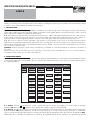
Upon switching on, just the central line (autotest) appears on the display for approximately three seconds and the subsequent indications depend
on the operating status of the controller. TABLE 1 gives the indications associated with the various states, whereas the symbols appearing below
are explained in TABLE 2.
2.1 STANDBY.If button is pressed for 3 seconds, it allows the LCD15 to be put on a standby, or to resume output control (with
parameter SB=YES only). An indication on the display shows that the outputs are off permanently.
2.2 NORMAL.During normal operation, the display shows the temperature measured by probe T1, presented in the most appropriate
manner. Parameter SCL may be adjusted in °C with auto-range (SCL=1°C), in °C with 1° fixed resolution (SCL=2°C) or in Fahrenheit
(SCL=°F). The measured temperature may be corrected with a fixed offset by assigning a value other than 0 to the parameter OS1.
Additionally, prior to display, the temperature is treated by an algorithm that allows the simulation of a thermal mass directly
OFF
0/I
INSTRUCTIONS FOR INSTALLATION AND USE.
LCD15
0LLCD008EN
S
TANDBY
N
ORMAL
I
NFO
M
ENU
I
NFO
D
ATA
S
ETUP
M
ENU
P
ARAMETER
V
ALUE
OFF -19 T1 -20 SCL 1°C
Not Product
Air Display scale
Operating Temper. (sim.)
temperature
DEF T2 -25 SPL -25
Defrost Evaporator Minimum
temperature setpoint
REC - - - - - - SPH -18
Recovery after .... Maximum
defrost setpoint
HI TLO -19 - - - - - -
High temperature Min. stored ....
alarm temperature
- - - CND 15 - - - - - -
.... Condenser clean ....
cycle
E1 LOC NO - - - - - -
Faulty T1 probe Locked keypad
TABLE 1

proportional to the SIM value. The result is a reduction in the fluctuation of the displayed value.
2.3 INFO MENU. Pressing the button and releasing it immediately activates the information selection menu. From this menu you
can display the instantaneous temperatures T1, T2 and T3; the maximum (THI) and minimum (TLO) stored temperature; the total
operating time of the condenser since its last cleaning (CND) and the keypad status (LOC). The information to be displayed can be
selected sequencially, by pressing repeatedly or quickly via the buttons and to scroll through the menu. Exit from the info
menu is by pressing button or automatic after 6 seconds of not using the keypad.
In the INFO operating mode it’s also possibile to reset the recordings THI and TLO and the hour counter CND by pressing buttons
+simultaneously while the value is displayed.
2.4 KEYPAD LOCK.The keypad lock avoids undesired, potentially dangerous operations, which might be attempted when the
controllers is operating in a public place. In the INFO mode, through the buttons and it’s possibile to assign YES or NO to the
parameter LOC. With LOC=YES all keypad commands are inhibited. To resume normal operation of keypad, adjust setting so that
LOC=NO.
2.5 DEFROSTING. By assigning a value grater than 0 to the parameter DDY, during defrost the indication is displayed instead of
the temperature. In this case, after defrost and for the time programmed in DDY, the display indication shows that the normal
thermostatic cycle is being resumed.
2.6 ALARM.An anomaly in the operation is displayed through the lighting up of an abbreviation showing its cause:
/
high/low
alarm temperature in the cabinet, door open, condenser high temperature, periodic condenser cleaning,
//
fault of
probe T1 / T2 / T3.
2.7 SETUP.The setup is accessed by pressing the buttons + + in succession and keeping them pressed simultaneously for 5
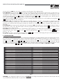
seconds. The available parameters appear in TABLE 2 as shown below.
3. CONFIGURATION
The controller is configured for the system to be controlled by programming the operating parameters, that is, through the setup (see par.
2.7). The instrument is dispatched with a general setup and the suitability of the parameters must therefore be checked before use. In
SETUP, press button to pass from one parameter to the next, and press button to go back. To display the value of a parameter
press , to modify it press buttons + or simultaneously. Exit from the setup is by pressing button or automatic after 30
seconds of not using the keypad. The setpoint SP (IISP) can be displayed and programmed even during normal operation of the
controller, by pressing button + or . The range will always remain within the limits SPL and SPH (IISL and IISH).
TABLE 2
CAUTION: upon changing the display scale SCL, it is ESSENTIAL to reconfigure the parameters related to the absolute (SPL, SPH, SP,
etc.) and differential (HYS, ATL, ATH, etc.) temperatures.
set
0/I
set
set
set
E3
E2
E1
CL
HP
DO
LO
HI
REC
DEF
0/I
set
0/I
set
set
INSTRUCTIONS FOR INSTALLATION AND USE.
SCL 1°C/2°C/°F Readout scale
SPL -40.. SPH [°] Minimum temperature set point
SPH SPL.. +40 [°] Maximum temperature set point
SP SPL.. SPH [°] Effective temperature set point
HYS +0.1.. +10.0 [°] Thermostat hysteresis
CRT 0.. 30 [min] Compressor rest time
CDC 0.. 10 Compressor regulation with sensor T1 failure
CSD 0.. 30 [min] Compressor stop delay from door opening
DFR 0.. 24 Defrosting frequency /24h
DLI -40.. +40 [°] Defrost end temperature
DTO 1.. 120 [min] Maximum defrosting duration
DTY OFF/ELE/GAS Defrost type
DRN 0.. 30 [min] Drain down time
DDY 0.. 60 [min] Defrosting display control
FID YES/NO Fans active during defrost
FDD -40.. +40 [°] Fan re-start delay temperature
FTC YES/NO Evaporator fan timed control
FPC 0.. 3 Evaporator fans ON/OFF ratio coefficient
ATL -12.. 0 [°] Low alarm differential
ATH 0.. +12 [°] High alarm differential
ATD 0.. 120 [min] Alarm temperature delay
ADO 0.. 30 [min] Door alarm delay
AHT 0.. 75 [°] Condenser alarm temperature
AHM NON/ALR/STP Condenser high temperature alarm operation
ACC 0.. 52 [weeks] Periodic condenser cleaning
HDS 1.. 5 Sensitivity function eco/heavy duty
IISM NON/MAN/HDD 2nd set switching mode
IISL -40.. IISH [°] Minimum 2nd temperature set
IISH IISL.. +40 [°] Maximum 2nd temperature set
IISP IISL.. IISH [°] Effective 2nd temperature set
IIHY +0.1.. +10.0 [°] Hysteresis of 2nd temperature set
IIDF 0.. 24 Defrosting frequency /24h in mode 2
IIFT YES/NO Evaporator fan timed control in mode 2
SB YES/NO Button enabling
DS YES/NO Door switch enabling
OS1 -12.. +12 [°] Probe T1 offset
T2 YES/NO Probe T2 enabling
OS2 -12.. +12 [°] Probe T2 offset
T3 YES/NO Probe T3 enabling
OS3 -12.. +12 [°] Probe T3 offset
TLD 1.. 30 [min] Delay for min./max. temperature storage
SIM 0.. 100 Display slowdown
ADR 1.. 255 Peripheral address
0/I

4. THERMOSTAT CONTROL
4.1 Thermostat control is based on comparing the temperature T1, the set point *SP and the hysteresis *HYS.
Example: SP= 2.0; HYS= 1.5, compressor Off with T1= +2.0° and On with T1= +3.5° (2+1.5).
The compressor only switches On again if the Off time period determined by CRT since the previous switchover has elapsed. Whenever
a very small hysteresis HYS must be maintained, it is advised that a suitable value for CRT is selected in order to reduce the number of
starts per hour.
4.2 If sensor T1 fails, the output is controlled by parameter CDC as a proportion of a 10 minute operating cycle.
Example: CDC=06, 6 minutes On, 4 minutes Off.
4.3 If door switch input control has been enabled (DS=YES), parameter CSD determines the delay between when the door is opened
and the compressor stopping.
* Actual setpoint and hysteresis depend on the selection I/II: in mode I, the reference parameters are SP and HYS while in mode II,
IISP and IIHY.
5. DEFROSTING
5.1 Defrosting starts automatically when necessary time has elapsed to obtain the defrosting frequency set with *DFR. For example,
with DFR=4 there will be 4 defrostings per 24 hours, so defrosting occurs once every 6 hours.
The internal timer is set to zero when power is applied to the controller and at each subsequent defrost start. When the controller is put
on a standby, the accumulated time count is “frozen” (is not incremented).
Defrosting may also be induced manually by keeping the button pressed for 2 seconds.
During a High Pressure alarm (see par. 7.3), defrost is suspended.
5.2 Once defrost has started, the outputs are controlled according to parameter DTY as per the following table:
TABLE 3
5.3 Defrost lasts for the time DTO but, if the evaporator probe has been enabled (T2=YES) and temperature DLI is achieved before
this time elapses, defrost will be terminated in advance.
If parameter DRN is greater than 0, before cooling starts all outputs will remain off for the time assigned to DRN. This phase, called
drain down, will allow a complete ice melting and the drain of the resulting water.
* The actual defrost frequency depends on the selection I/II: in mode I, the reference parameter is DFR while in mode II it’s IIDF.
6. EVAPORATOR FANS
6.1 During thermostatic control, the evaporator fans are controlled by parameter *FTC and FPC. With FTC=NO, the fans operate
continuously regardless of the FPC value set. Alternatively, when FTC=YES the evaporator fans will operate in conjunction with the
compressor (i.e. when the compressor runs the fans will run), but dependant upon the FPC value set they will On/Off cycle after the
compressor has stopped. With FPC set between 1 to 3, you will obtain On/Off ratios of respectively, 33%, 50% and 60% with fixed
60 second off times. Therefore, once the compressor has stopped, with FPC=1 (33%) the fans will run for 30 seconds and stay off for
60 seconds. If FPC=2 (50%) the fans will run for 60 seconds and remain off for 60 seconds; with FPC=3 (60%) the fans will run for 90
seconds and stay switched off for 60 seconds. This cycle pattern will continue until the compressor starts again. With FPC=0, the fans
will follow the compressor cycle only.
This fan control function aims at recovering the maximum cooling effect available at the evaporator as well as greatly reducing unwanted
heat generated by the evaporator fan motors, so increasing the energy efficiency. Cycling the fans also avoids air stratification, and
allowing the temperature measured by probe “T1” to be updated, and thus accurate. If the temperature to be maintained is above
freezing then the maximum humidity is maintained in the chilled environment.
6.2 If the LCD15 is connected to a door switch and door switch control is enabled (DS=YES), during thermostatic control if the door is
opened, the fans will be stopped immediately.
6.3 During defrost, the fans are controlled by parameter FID; with FID=YES the fans remain on all through defrosting. With FID=NO,
the fans will be stopped and will only re-start when the conditions in paragraph 6.4 have been met.
6.4 After defrosting, if probe T2 is active (T2=YES), temperature FDD provides evaporator fan re-start. So the evaporator fans will not
run until the evaporator has a temperature lower than FDD. If such condition doesn’t occur within 4 minutes following defrost termination,
the fans will however be switched on again.
INSTRUCTIONS FOR INSTALLATION AND USE.
DTY DEFROST COMPRESSOR
OFF Off Off
ELE On Off
GAS On On

* The way the fans will be controlled depends on the selection I/II: in mode Ithey work according to FTC, while in mode II the fans
work according to IIFT.
7. ALARMS
With LCD15, correct operation of the refrigerator and thermostat may be monitored by a wide range of functional and diagnostics
alarms, individually selectable by means of the relevant parameters. The alarm warnings are given on the display through explicit
indications (see following par.) and intermittent buzzer sounding. During an alarm, by pressing any button, the buzzer is muted.
Then, if the alarm persists, the buzzer will be periodically switched on for 20 seconds every 60 minutes, until the alarm ends (the
display indications remain on all the time). The repeated acoustic warning applies to all alarms with the exception of the condenser
cleaning alarm. Operation of the various elements is given in detail below.
7.1 The parameters ATL and ATH define two differential temperatures that, referred to the set point, determine the temperature
alarm thresholds. ATL establishes the alarm differential for temperatures below set point, ATH the alarm differential for temperatures
above set point + hysteresis. Putting one or both differentials to 0 cuts out the corresponding alarm.
Example: SP= -20, HYS= 2.0, ATL= -5.0, ATH= 05.0; the alarm thresholds are set at –25°(-20-5) and –13° (-20+2+5).
The alarm warning may be immediate or delayed by the time ATD whenever this is greater than 0. The indication for high
temperature and for low temperature alarm blinks on the display. The alarm indication remains stored in the display, even
when the alarm is over, until you acknowledge the alarm manually by pressing any button.
The high temperature alarm is bypassed during defrosting.
7.2 If a suitable door switch has been connected to detect the door status and door switch input control has been enabled
(DS=YES), the door open alarm function is enabled. In this way, if the door remains open the controller will react after the time
delay set with ADO by displaying the alarm source through the indication .
7.3 To monitor the condenser temperature to avoid gas pressure from getting too high, it’s necessary to secure probe T3 to the
condenser firmly (see 1.3) and enable condenser probe control (T3=YES). Parameter AHT determines the condenser temperature
alarm threshold and parameter AHM determines the reaction following the temperature rising over AHT. With AHM=ALR the only
reaction will be the buzzer sounding and being displayed. Alternatively, with AHM=STP, besides the alarm indication the
compressor will be stopped immediately and defrosts suspended.
With AHM=NON, all functions related to the High Pressure alarm are inhibited.
7.4 Assigning a value greater than 0 to the parameter ACC enables the indication for periodic cleaning of the condenser.
Subsequently, when the count of compressor hours of operation reaches the equivalent in weeks set with ACC, an indication for
cleaning appears on the display.
Example: with ACC=16 there is a warning once every 16x7(weeks)x24(hours)=2688 hours of compressor operation, so, assuming for this
an operation with 5 minutes On and 5 minutes Off - after approx. 32 weeks.
In order to clear the time counter, follow the prescribed procedure in paragraph 2.3.
7.5 Upon failure of probe T1 or, if enabled, probes T2 and T3, probe failure is signalled with the blinking indication
or or
respectively.
8. TEMPERATURE STORAGE
The LCD15 features a system for permanent storage of the minimum and maximum temperature logged during operation. This system is
a valid help to achieve compliance with the HACCP directive in its part relating to a correct preservation of foodstuffs. Temperature is
measured by probe T1 which should therefore be placed in a point where the temperature of the preserved product may always be
measured correctly. The logging is however subject to some simple rules that filter the data and give a rational interpretation. The logging
is suspended during the periods in which the refrigerator is put on a standby and during defrostings and, during the normal operation
(thermostatic control), it’s “slowed down” through the parameter TLD. This parameter defines the time during which the measured
temperature must permanently exceed the current value before the logging is performed. In this way, it will be possible to avoid idle
loggings that don’t reflect the actual product temperature, for example, the door being left open, the temperature recovery after a defrost
or other temporary short term temperature huntings.
It is suggested that a reasonably long TLD time is programmed, for instance 5-15 minutes, you then put the product into the refrigerator
and start a new logging cycle by clearing previous values (see par. 2.3). It will now suffice that at regular intervals, in the INFO menu
you check the minimum and maximum logged values in order to know if the product has been kept within the required temperature limits.
9. AUXILIARY FUNCTIONS
9.1 In addition to the basic functions described above, The LCD15 offers an innovative feature to enhance the performance of the
refrigerator. Infact, you can select the control parameters between two different pre-programmed groups, in order for the fundamental
control parameters to be adapted quickly to changing needs such as, for example: High/Low Temperature range change, stored product
change (meat, fish, vegetables …), maximum cooling capacity or energy saving. The parameters switched over in mode I and II are:
SPL, SPH, SP, HYS, DFR, FTC and IISL, IISH, IISP,IIHY, IIDF, IIFT.
E3
E2
E1
HP
DO
LO
HI
INSTRUCTIONS FOR INSTALLATION AND USE.

With the parameter IISM you select if the changeover from Group Ito Group II is made manually via the button (IISM=MAN), or
automatically when heavy duty operation is detected (IISM=HDD) or inhibited (IISM=NON). The activation of Group II is signalled by
the lighting up of the relevant LED on the controller display.
9.2 The automatic detection of “heavy duty operation” allows the control parameters to be modified in response to the specific
temporary needs of the refrigerator, such as: warm food being put into the cabinet, door being opened frequently etc. Control sensitivity
to switch over from Group I to Group II is determined by parameter HDS (1=minimum, 5=maximum). An example of how to use such
function is reported in the following table:
If we apply the above example to a refrigerator in a restaurant kitchen the controller will use the parameters of Group I during the closing
times of the kitchen, when the need for cooling is minimum, therefore we can consider this as a “normal” operation condition. Group I
“economy control” parameters will ensure both an optimum foodstuff preservation and considerable energy saving. Alternatively, during
very busy periods (door being opened continuously to take out or load food), the controller will automatically select Group II to try and
maintain the average product temperature within correct values (lower setpoint), limit compressor wear by reducing the number of starts
(higher hysteresis), avoid long defrost pauses which will worsen the preservation condition (lower defrost frequency or no defrosts at all),
increase product cooling speed by keeping ventilation always active (FCT=NO). When the heavy duty period is over, the controller will
automatically resort back to Group I.
NOTE: To make the automatic detection IISM=HDD work better, it is suggested that the value of hysteresis is not set too narrow (less than
2°K) or the value of CRT is not set too high (longer than 2 minutes)
9.3 The controller is provided with a serial port for connection to a PC or a programmer. In the first case it is important to assign to the
parameter ADR a different value for each linked unit (peripheral address); with automatic programming, ADR should remain on 1.
WARRANTY
LAE electronic SPA guarantees its products against defects due to faulty materials or workmanship for one (1) year from the date of manufacture shown on the container.
The Company shall only replace products which are shown to be defective to the satisfaction of its own technical services. The Company shall not be under any liability
and gives no warranty in the event of defects due to exceptional conditions of use, misuse or tampering.
LAE electronic does not accept units back unless LAE electronic has previously given its allowance or request.
II
INSTRUCTIONS FOR INSTALLATION AND USE.
PARAMETER GROUP IGROUP II
Setpoint
SP= -18 IISP= -21
Hysteresis HYS= 2.0 IIHY= 3.0
Defrost frequency DFR= 3 IIDF= 1.. 0
intermit. fans FTC= YES IIFT= NO

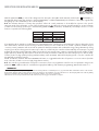
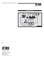
7(2)A 7(2)A 7(2)A
Aux
RS485
PC comm.
Power
supply
A
B
Door
switch
131415161718
52413
WIRING DIAGRAM
LCD15CS3E-B
VIA PADOVA, 25
31046 ODERZO /TV /ITALY
TEL. 0422 815320 - 815303
TELEFAX 0422 814073
www.lae-electronic.com
E-mail: [email protected]
PARTNER VENEZIA • 041 5460713
INSTRUCTIONS FOR INSTALLATION AND USE.
-
 1
1
-
 2
2
-
 3
3
-
 4
4
-
 5
5
-
 6
6


LAE LCD15 Instructions For Installation And Use Manual
- Type
- Instructions For Installation And Use Manual
Ask a question and I''ll find the answer in the document
Finding information in a document is now easier with AI
Related papers

Other documents
-
Foster SLIMLINE FSL400 Original Service Manual
-
-
-
Full Gauge Controls t-core +ECO Owner's manual
-
 KingsBottle KBU-25S-FG PRO Owner's manual
-
-
True STR, STA, STG Installation guide
-
Foster XR600H User manual
-
Vemer AHT J - 1P4A User manual
-
Endres+Hauser Nivo Operating instructions
