Page is loading ...

TECHNISCHE DATEN
Spannungsversorgung
AT1-5…E 230Vac±10%, 50 /60Hz, 3W
AT1-5…U 115Vac±10%, 50/60Hz, 3W
AT1-5...D 12Vac/dc±10%, 3W
Relaisausgänge
AT1-5.Q1(2)… Verdichter 12(4)A
AT1-5.S1(2)… Verdichter 16(4)A
AT1-5.Q3(4)… Verdichter 12(5)A
AT1-5.S3(4)… Verdichter 16(5)A
AT1-5.Q5(6)… Verdichter 12(8)A
AT1-5.S5(6)… Verdichter 16(8)A
Hilfslasten 7(2)A 24 0vac
AT1-5.Q… maximaler Strom 12A
AT1-5.S… maximaler Strom 16A
Eingänge
NTC 10KΩ@25°C, LAE-Code SN4...
PTC 1000Ω@25°C, LAE-Code ST1…
Messbereich
-50…120°C, -55…240°F
-50 / -9.9 … 19.9 / 80°C (nur bei NTC10K)
Messgenauigkeit
<0.5°C im Messbereich
Betriebsbedingungen
-10 … + 50°C; 15…80% rF
CE – UL (Zer tifizierungen und Bezugsnormen)
EN60730-1; EN60730-2-9;
EN55022 (Klasse B) ;
EN50082-1
UL 60730-1A
Frontschutzart
IP55
PARTNER VENEZIA • 041 5460713
AT1-5
INSTRUCTIONS FOR USE
BEDIENUNGSANLEITUNG
EN
DE
0LAT1001-01
VIA PADOVA, 25
31046 ODERZO /TV /ITALY
TEL. +39 - 0422 815320
FAX +39 - 0422 814073
www.lae-electronic.com
E-mail: [email protected]
AT1-5
INSTRUCTIONS FOR USE
BEDIENUNGSANLEITUNG
AT1-5 BEDIENUNGSANLEITUNG
Wir danken Ihnen, dass Sie sich für ein Produkt der Firma LAE electronic entschieden haben. Lesen Sie vor der Installation
des Gerätes bitte aufmerksam die vorliegende Bedienungsanleitung durch: Nur so können wir Ihnen höchste Leistungen und
Sicherheit garantieren.
BESCHREIBUNG ANGABEN
Wärmeregelungsausgang
Hilfsausgang
Alarm
Abb. 1 — Bedienteil
Taste Info / Setpoint. Taste Manuelle Abtauung / Down.
Taste Up / Manueller Modus. Taste Exit / Stand-by.
INSTALLATION
Das Gerät in eine Bohrung der Abmessungen 71x29 mm einsetzen.
Die Elektroanschlüsse ausführen (siehe hierzu die „Schaltpläne“). Zur Vermeidung von elektromagnetischen Störungen die
Fühler- und Signalkabel getrennt von den Starkstromleitern anbringen.
Das Gerät mit den beiliegenden Halterungen an der Tafel mit leichtem Druck befestigen; falls vorhanden muss die
Gummidichtung zwischen Geräterahmen und Tafel angebracht werden. Auf die korrekte Positionierung achten, um das
geräterückseitige Eindringen von Flüssigkeiten zu vermeiden.
Den Fühler T1 so in der Zelle positionieren, dass die Konservierungstemperatur des Produktes gut gemessen werden kann.
Den Fühler T2 auf dem Verdampfer an der Stelle des maximalen Reifeansatzes befestigen.
BETRIEB
DISPLAYANZEIGEN
Im Normalbetrieb zeigt das Display die Messtemperatur oder einen der folgenden Werte an:
DEF Abtauung wird ausgeführt HI Übertemperaturalarm in der Zelle
REC SW-Wiederherstellung nach Abtauung LO Untertemperaturalarm in der Zelle
OFF Regler im Stand-by-Modus E1 Defekt in Fühler T1
CL Anforderung der Verfl üssigerreinigung E2 Defekt in Fühler T2
DO Alarm für Tür offen
INFO-MENÜ
Die im Info-Menü abrufbaren Daten sind:
T1 Ist-Temperatur des Fühlers 1
TLO
Min. Messtemperatur des Fühlers 1
T2 Ist-Temperatur des Fühlers 2
CND
Verdichterbetriebszeit in Wochen
THI Max. Messtemperatur des Fühlers 1
LOC
Tastenzustand ( Sperre )
Zugriff auf das Menü und Datenanzeige
Die Taste
drücken und loslassen.
Mit den Tasten
oder
die anzuzeigenden Daten wählen.
Mit der Taste
den Wert anzeigen.
Zum Verlassen des Menüs die Taste
X
drücken oder 10 Sekunden warten.
Reset der gespeicherten Werte THI, TLO, CND
Mit den Tasten
oder
den zu resettierenden Wert wählen.
Mit der Taste
den Wert anzeigen.
Die Taste
gedrückt halten und gleichzeitig die Taste
X
drücken.
SETPOINT (Anzeige und Änderung des Sollwertes - gewünschter Temperaturwert)
Die Taste
mindestens für eine halbe Sekunde drücken, um den Sollwert anzuzeigen.
Die Taste
gedrückt halten und mit den Tasten
oder
den gewünschten Wert einstellen (die Regelung kann innerhalb
des Mindestwertes SPL und Höchstwertes SPH erfolgen).
Beim Loslassen der Taste
wird der neue Wert gespeichert.
STAND-BY
Die Taste , lässt, falls für 3 Sekunden gedrückt, den Regler auf verschiedene Betriebsmodi oder Stand-by umschalten (nur
bei SB=YES).
TASTENSPERRE
Die Sperre der Tasten verhindert unerwünschte und potenziell schädliche Handlungen, sollte der Regler beispielsweise in
einer öffentlich zugänglichen Umgebung positioniert sein. Zur Sperre aller Tastenbefehle den Parameter im INFO-Menü auf
LOC=YES einstellen; zur Wiederherstellung aller Funktionen den Parameter auf LOC=NO setzen.
ABTAUUNG
Abtauung mit Timer. Eine Abtauung wird jedes Mal dann automatisch gestartet, wenn im internen Timer die Zeit der
Abtaufrequenz, bestimmt durch DFR, verstreicht. Beispiel: mit DFR=4 erfolgen 4 Abtauungen innerhalb 24 Stunden, d.h. eine
Abtauung alle 6 Stunden. Der interne Timer wird beim Einschalten des Gerätes und bei jedem neuen Abtaustart auf Null
gestellt; im Standby wird die Zählung gestoppt (läuft nicht weiter).
Manuelle Abtauung. Durch Drücken der Taste
für 2 Sekunden kann eine manuelle Abtauung aktiviert werden.
Abtautyp. Nach dem Start der Abtauung werden die Verdichter- und Abtauausgänge gemäß den Parametern DTY und OAU
angesteuert. Der AUX-Ausgang ist nämlich nur bei OAU = DEF an die Abtaufunktion gebunden.
Abtauende. Die Abtauung endet bei Erreichen der Zeit DTO; sollte der Verdampferfühler aktiviert sein (T2=YES) und innerhalb
dieser Zeit die Temperatur DLI erreicht werden, endet die Abtauung vorzeitig.
Achtung: Bei C-H=HEA sind alle Abtaufunktionen gesperrt; bei DFT=0 ist nur die getimte Abtaufunktion ausgeschlossen.
Während einer Abtauung ist der Übertemperaturalarm gesperrt.
KONFIGURATIONSPARAMETER
Für den Zugriff auf das Konfi gurationsmenü die Tasten
X
+
für 5 Sekunden drücken.
Mit den Tasten
oder
den zu ändernden Parameter wählen.
Mit der Taste
den Wert anzeigen.
Die Taste
gedrückt halten und mit den Tasten
oder
den gewünschten Wert einstellen.
Beim Loslassen der Taste
wird der neue Wert gespeichert und der nächste Parameter angezeigt.
Zum Verlassen des Menüs die Taste
X
drücken oder 30 Sekunden warten.
PAR
MESSBEREICH
BESCHREIBUNG
SCL
1°C;
2°C;
°F
Anzeigeskala.
1°C (nur bei INP=SN4) : Messbereich -50/-9.9 … 19.9/80°C.
2°C: Messbereich -50 … 120°C.
°F: Messbereich -55 … 240°F.
Achtung : Bei der Änderung des Wertes SCL müssen die Parameter der absoluten und relativen Temperaturen (SPL,
SPH, SP, ALA, AHA, usw.) unbedingt neu konfiguriert werden.
SPL
-50..SPH Mindestgrenzwert für die Regelung von SP.
SPH
SPL .120° Höchstgrenzwert für die Regelung SP.
SP
SPL ... SPH Schalttemperatur (Wert, der in der Zelle beibehalten werden soll) .
C-H
REF; HEA Kühlmodus (REF) oder Heizmodus (HEA).
HYS
1...10° OFF/ON-Schalthysterese des Thermostaten.
Kühlregelung (C-H=REF) Heizregelung (C-H=HEA)
CRT
0...30Min Verdichterstoppzeit. Eine Neuaktivierung des Ausganges kann nur nach Verstreichen von CRT Minuten nach dem
vorherigen Ausschalten er folgen. Empfohlene Werte: CRT=03 bei HYS<2.0°.
CT1
0...30Min Aktivierungszeit des Wärmeregelungsausganges während einer Funktionsstörung des Fühlers T1. Bei CT1=0 ist
der Ausgang immer OFF.
CT2
0...30Min Stoppzeit des Wärmeregelungsausganges während einer Funktionsstörung des Fühlers T1. Bei CT2=0 ist der
Ausgang immer ON.
Beispiel: CT1=4, CT2= 6: Im Fall eines Defektes des Fühlers T1 arbeitet der Verdichter mit 4-minütigen ON-Zyklen
und 6-minütigen OFF-Zyklen.
CSD
0..30Min Verzögerung des Verdichterstopps nach Türöffnung (aktiv nur bei DS = YES).
DFR
0...
24(1/24Std)
Abtaufrequenz in Zyklen/24 Stunden.
DLI
-50...120° Abtauendtemperatur.
DTO
1...120Min Maximale Abtaudauer.
DTY
OFF;
ELE;
GAS
Abtautyp.
OFF: Abtauung bei Stopp (Verdichter und Abtauheizung OFF).
ELE: Elektrische Abtauung* (Verdichter OFF und Abtauheizung ON).
GAS: Heißgasabtauung* (Verdichter und Abtauheizung ON) .
* Der Abtauausgang wird bei OAU=DEF gesteuert.
DDY
0...60Min Displayanzeige während Abtauung. Bei DDY=0 zeigt das Display während einer Abtauung auch weiterhin die
Temperatur an. Bei DDY > 0 zeigt das Display während einer Abtauung die Zeichen DEF und nach Beendung dieser
die Zeichen REC für DDY Minuten an.
ATM
NON;
ABS;
REL
Alarmschwellen.
NON: Alle Temperaturalarme sind gesperrt (der nächste Parameter ist ADO).
ABS: Die in ALA und AHA programmierten Werte stellen die effektiven Alarmschwellen dar.
REL: Die in ALR und AHR programmierten Werte sind die Alarmdifferentiale für SP und SP+HY.
Temperaturalarm mit entsprechenden Alarmschwellen Temperaturalarm mit entsprechenden Alarmschwellen
in Kühlregelung (ATM =REL, C-H=REF). in Heizregelung (AT M =REL, C-H=HEA).
ALA
-50... 12 0° Alarmschwelle für Untertemperatur.
AHA
-50... 12 0° Alarmschwelle für Über temperatur.
ALR
-12... 0° Alarmdifferential für Unter temperatur. Bei ALR= 0 wird der Untertemperaturalarm ausgeschlossen.
AHR
0... 12° Alarmdifferential für Übertemperatur. Bei AHR= 0 wird der Übertemperaturalarm ausgeschlossen.
ATD
0... 120Min Verzögerung der Temperaturalarmmeldung.
ADO
0... 30Min Verzögerung der Alarmmeldung für Tür of fen.
ACC
0...52
Wocken
Periodische Verflüssigerreinigung. Sobald die Verdichterbetriebszeit (in Wochen) den Wer t ACC erreicht, blinken
auf dem Display die Zeichen “CL”. Bei ACC= 0 wird die Verflüssigerreinigungsmeldung ausgeschlossen.
SB
NO/YES Aktivierung der Stand-by-Taste .
DS
NO/YES Aktivierung des Türeingangsfühlers (geschlossen bei Tür geschlossen).
OAU
NON;
0-1;
DEF;
LGT;
ALR;
Funktionen des Hilfsausganges AUX.
NON: Ausgang deaktiviert (immer ausgeschaltet).
0-1: Die Relaiskontakte folgen dem ON-/Stand-by-Zustand des Reglers.
DEF: Ausgang für Abtausteuerung aktiviert.
LGT: Ausgang für Lichtsteuerung aktivier t.
ALR: Schließung der Kontakte im Alarmfall.
INP
SN4; ST1 Wahl des Temperaturfühlers. Bei INP = SN4 müssen die Fühler den Modellen L AE SN4.. entsprechen; bei INP = ST1
den Modellen LAE ST1...
OS1
-12.5..12.5°C Messwertkorrektur des Fühlers T1.
T2
NO/YES Aktivierung des Fühlers T2 (Verdampfer).
OS2
-12.5..12.5°C Messwertkorrektur des Fühlers T2.
TLD
1...30 Min Verzögerung der Mindesttemperatur- (TLO) und Höchsttemperaturspeicherung (THI).
SIM
0...100 Displayverlangsamung.
ADR
1...255 Adresse von AT1-5 für Kommunikation mit einem PC.
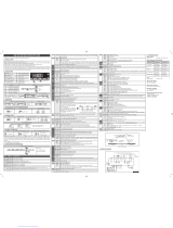
SCHALTPLÄNE
16(5)A
T1
ComT2
7(2)A
230Vac
54231
78 91110
TTL
AUX
16A
Türschalter
AT1-5BS4E-AG
16(8)A
T1
ComT2
Türschalter
7(2)A
230Vac
54231
78 91110
RS485
AUX
16A
AT1-5BS6E-BG
16(8)A
T1
7(2)A
230Vac
54231
78 10
RS485
AUX
16A
11
Türschalter
AT1-5AS6E-BG
ISTR AT1-5 TEDESCO.indd 1ISTR AT1-5 TEDESCO.indd 1 3-10-2007 9:54:083-10-2007 9:54:08

AT1-5 INSTRUCTIONS FOR USE
Thank you for having chosen a LAE electronic product. Before installing the instrument, please read these instructions carefully
to ensure maximum performance and safety.
DESCRIPTION INDICATIONS
Thermostat output
Auxiliary output
Alarm
Fig.1 — Front panel
Info / Setpoint button. Increase / manual activation button.
Manual defrost / Decrease button. Exit / Stand-by button.
INSTALLATION
Insert the controller through a hole measuring 71x29 mm.
Make sur e that e le c trical c onnections com ply with t he paragra p h “wir ing diagr ams”. To reduce the ef fects of el e ctromagn e tic
disturbance, keep the sensor and signal cables well separate from the power wires.
Fix the controller to the panel by means of the suitable clips, by pressingly gently; if fi tted, check that the rubber gasket
adheres to the panel perfectly, in order to prevent debris and moisture infi ltration to the back of the instrument.
Place the probe T1 inside the room in a point that truly represents the temperature of the stored product.
Place the probe T2 where there is the maximum formation of frost.
OPERATION
DISPLAY
During normal operation, the display shows either the temperature measured or one of the following indications:
DEF Defrost in progress HI Room high temperature alarm
REC Recovery after defrost LO Room low temperature alarm
OFF Controller in stand-by E1 Probe T1 failure
CL Condenser clean warning E2 Probe T2 failure
DO Door open alarm
INFO MENU
The information available in this menu is:
T1 Instant probe 1 temperature
TLO
Minimum probe 1 temperature recorded
T2 Instant probe 2 temperature
CND
Compressor working weeks
THI Maximum probe 1 temperature recorded
LOC
Keypad state lock
Access to menu and information displayed.
Press and immediately release button .
With button
or
select the data to be displayed.
Press button
to display value.
To exit from the menu, press button
X
or wait for 10 seconds.
Reset of THI, TLO, CND recordings
With button
or
select the data to be reset.
Display the value with button .
While keeping button
pressed, use button
X
.
SETPOINT (display and modifi cation of desired temperature value)
Press button
for at least half second, to display the setpoint value.
By keeping button
pressed, use button
or
to set the desired value (adjustment is within the minimum SPL and the
maximum SPH limit).
When button
is released, the new value is stored.
STAND-BY
Button , when pressed for 3 seconds, allows the controller to be put on a standby or output control to be resumed (with
SB=YES only).
KEYPAD LOCK
The keypad lock avoids undesired, potentially dangerous operations, which might be attempted when the controllers is
operating in a public place. In the INFO menu, set parameter LOC=YES to inhibit all functions of the buttons. To resume normal
operation of keypad, adjust setting so that LOC=NO.
DEFROST
Timed defrost. Defrosting starts automatically when necessary time has elapsed to obtain the defrosting frequency set with
DFR. For example, with DFR= 4 defrosting occurs once every 6 hours. The internal timer is set to zero when power is applied
to the controller and at each subsequent defrost start. When the controller is put on a standby, the accumulated time count is
“frozen” (is not incremented).
Manual defrost. Defrosting may also be induced manually by keeping the button
pressed for 2 seconds.
Defrost type. Once defrost has started, Compressor and Defrost outputs are controlled according to the parameters DTY and
OAU. The AUX output is associated to defrost function with OAU =DEF exclusively.
Defrost termination. Defrost lasts as long as time DTO but, if the evaporator probe has been enabled (T2=YES) and
temperature DLI is achieved before this time elapses, defrost will be terminated in advance.
Caution: if C-H= HEA all defrost functions are inhibited; if DFR=0 the timed defrost function is excluded; during defrost, the high
temperature alarm is inhibited.
CONFIGURATION PARAMETERS
The setup menu is accessed by pressing button
X
+
for 5 seconds.
With button
or
select the parameter to be modifi ed.
Press button
to display the value.
By keeping button
pressed, use button
or
to set the desired value.
When button
is released, the newly programmed value is stored and the following parameter is displayed.
To exit from the setup, press button
X
or wait for 30 seconds.
PAR RANGE DESCRIPTION
SCL
1°C;
2°C;
°F
Readout scale.
1°C (only with INP= SN4) : measuring range -50/-9.9 … 19.9/8 0°C
2°C : measuring range -50 … 120°C
°F : measuring range -55 … 240°F
Caution: upon changing the SCL value, it is then absolutely necessary to reconfigure the parameters relevant to the
absolute and relative temperatures (SPL, SPH, SP, ALA, AHA, etc.. )
SPL
-50..SPH Minimum limit for SP setting
SPH
SPL .120° Maximum limit for SP setting
SP
SPL ... SPH Setpoint (value to be maintained in the room).
C-H
REF; HEA Refrigerating (REF) or Heating (HE A) control mode
HYS
1...10° OFF/ON thermostat differential
Refrigerating control (C-H=REF ) Heating control (C-H=HEA)
CRT
0...30min Compressor rest time. The output is switched on again after CRT minutes have elapsed since the previous
switchover. We recommend to set CRT=03 with HYS<2.0°.
CT1
0...30min Thermostat output run when probe T1 is faulty. With CT1= 0 the output will always remain OFF.
CT2
0...30min Thermostat output stop when probe T1 is fault y. With CT2=0 and CT1>0 the output will always be ON.
Example: CT1=4, CT2= 6: In case of probe T1 failure, the compressor will cycle 4 minutes ON and 6 minutes OFF.
CSD
0..30min Compressor stop delay af ter the door has been opened (active only if DS=YES).
DFR
0... 24(1/24h) Defrost frequency expressed in cycles/24 hours.
DLI
-50...120° Defrost end temperature.
DTO
1...120min Maximum defrost duration.
DTY
OFF;
ELE;
GAS
Defrost type
OFF: off cycle defrost (Compressor and Heater OFF).
ELE: electric defrost* (Compressor OFF and Heater ON).
GAS: hot gas defrost* ( Compressor and Heater ON).
* The defrost output is active if only OAU=DEF.
DDY
0...60min Display during defrost. If DDY=0 during defros t the temperature continues to be displayed. If DDY > 0, during defrost
the display shows DEF, when defrost is over REC is displayed during DDY minutes.
ATM
NON;
ABS;
REL
Alarm threshold management.
NON: all temperature alarms are inhibited (the following parameter will be ADO).
ABS: the values programmed in ALA and AHA represent the real alarm thresholds.
REL: the values programmed in ALR and AHR are alarm differentials referred to SP and SP+HY.
Temperature alarm with relative thresholds, Temperature alarm with relative thresholds,
refrigerating control (ATM=REL, C-H=REF). heating control (ATM=REL, C-H=HEA).
ALA
-50... 12 0° Low temperature alarm threshold.
AHA
-50... 12 0° High temperature alarm threshold.
ALR
-12... 0° Low temperature alarm dif ferential. With ALR=0 the low temperature alarm is excluded.
AHR
0... 12° High temperature alarm differential. With AHR= 0 the high temperature alarm is excluded.
ATD
0... 120min Delay before alarm temperature warning.
ADO
0... 30min Delay before door open alarm warning.
ACC
0...52
weeks
Condenser periodic cleaning. When the compressor operation time, expressed in weeks, matches the ACC value
programmed, “CL” flashes in the display. With ACC = 0 the condenser cleaning warning is disabled.
SB
NO/YES Stand-by button enabling .
DS
NO/YES Door switch input enabling (closed when door is closed).
OAU
NON;
0-1;
DEF;
LGT;
ALR;
AUX output operation
NON : output disabled (always off).
0-1 : the relay contacts follow the on/standby state of controller.
DEF: output programmed for defrost control.
LGT : output enabled for light control.
ALR : contacts make when an alarm condition occurs.
INP
SN4; ST1 Temperature sensor selection. With INP = SN4, the probes must be the L AE models S N4.. ; with INP = ST1, the probes
must be the LAE models ST1...
OS1
-12.5..12.5°C Probe T1 offset.
T2
NO/YES Probe T2 enabling (evaporator).
OS2
-12.5..12.5°C Probe T2 offset.
TLD
1...30 min Delay for minimum temperature (TLO) and maximum temperature (THI) logging.
SIM
0...100 Display slowdown.
ADR
1...255 AT1-5 address for PC communication.
WIRING DIAGRAM
TECHNICAL DATA
Power supply
AT1-5…E 230Vac±10%, 50 /60Hz, 3W
AT1-5…U 115Vac±10%, 50/60Hz, 3W
AT1-5…D 12Vac±10%, 50/60Hz, 3W
Relay outputs
AT1-5.Q1(2)… compressor 12(4)A
AT1-5.S1(2)… compressor 16(4)A
AT1-5.Q3(4)… compressor 12(5)A
AT1-5.S3(4)… compressor 16(5)A
AT1-5.Q5(6)… compressor 12(8)A
AT1-5.S5(6)… compressor 16(8)A
Auxiliary loads 7(2)A 240vac
AT1-5.Q… maximum total current 12A
AT1-5.S… maximum total current 16A
Inputs
NTC 10KΩ@25°C, LAE part No. SN4...
PTC 1000Ω@25°C, LAE part No. ST1…
Measuring Range
-50…120°C, -55…240°F
-50 / -9.9 … 19.9 / 80°C (with NTC10K only)
Measuring accuracy
<0.5°C within the measurement range
Operating conditions
-10 … +50°C; 15%...80% r.H.
CE – UL (Approvals and Reference Norms)
EN60730-1; EN60730-2-9;
EN55022 (Class B);
EN50082-1
UL 60730-1A
Front protection
IP55
VIA PADOVA, 25
31046 ODERZO /TV /ITALY
TEL. +39 - 0422 815320
FAX +39 - 0422 814073
www.lae-electronic.com
E-mail: [email protected]
PARTNER VENEZIA • 041 5460713
16(5)A
T1
ComT2
door
switch
7(2)A
230Vac
54231
78 91110
TTL
AUX
16A
door
AT1-5BS4E-AG
OFF
ON
SP SP+HY
T[°]
OFF
ON
SPSP-HY
T[°]
OFF
ON
SP SP+HYS+AHRSP
-
ALR
T[°] OFF
ON
SPSP
-
HYS
-
ALR SP+AHR
T[°]
16(8)A
T1ComT2
7(2)A
230Vac
54231
78 91110
RS485
AUX
16A
door
switch
door
AT1-5BS6E-BG
16(8)A
T1
7(2)A
230Vac
54231
78 10
RS485
AUX
16A
11
door
switch
door
AT1-5AS6E-BG
ISTR AT1-5 INGLESE ITALIANO.indd1 1ISTR AT1-5 INGLESE ITALIANO.indd1 1 12-12-2007 12:01:1012-12-2007 12:01:10
/