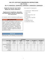
Weil-McLain GV boiler, a reliable and efficient heating solution, offers precise temperature control, ensuring a comfortable indoor environment. Its advanced gas/air manifold assembly enables efficient fuel utilization, resulting in lower energy bills. Installation and maintenance are simplified with the provided detailed instructions and recommended tools.
Weil-McLain GV boiler, a reliable and efficient heating solution, offers precise temperature control, ensuring a comfortable indoor environment. Its advanced gas/air manifold assembly enables efficient fuel utilization, resulting in lower energy bills. Installation and maintenance are simplified with the provided detailed instructions and recommended tools.

-
 1
1
Weil-McLain GV Operating instructions
- Type
- Operating instructions
- This manual is also suitable for
Weil-McLain GV boiler, a reliable and efficient heating solution, offers precise temperature control, ensuring a comfortable indoor environment. Its advanced gas/air manifold assembly enables efficient fuel utilization, resulting in lower energy bills. Installation and maintenance are simplified with the provided detailed instructions and recommended tools.
Ask a question and I''ll find the answer in the document
Finding information in a document is now easier with AI
Related papers
-
Weil-McLain GV Operating instructions
-
Weil-McLain CGi User manual
-
Weil-McLain 381357870 User manual
-
Weil-McLain GOLD CGi-4E User manual
-
Weil-McLain CG User manual
-
Weil-McLain 550-110-710/0107 User manual
-
Weil-McLain CG User manual
-
Weil-McLain Boiler 550-110-260/0107 User manual
-
Weil-McLain CGt Gas Boiler User manual
-
Weil-McLain GOLD CGS 550-110-260/02002 User manual
Other documents
-
Dunkirk Q90-100 Series IV Operating instructions
-
Dunkirk Q90-100 Series IV Installation & Operation Manual
-
Weil Mclain 381357913 Installation guide
-
Lennox International Inc. Water Dispenser Gas-Fired Hot Water Boiler User manual
-
Dunkirk Q90-100 Series IV Installation & Operation Manual
-
Dunkirk Q90-100 Series IV Installation & Operation Manual
-
 UTICA BOILERS Q90-100 Series IV Operating instructions
-
Dunkirk QL Installation & Operation Manual
-
Burnham IN7 User manual
-
Dunkirk Q90-100 Series IV Installation & Operation Manual

