Page is loading ...

Part No. 550-110-260/0508
This manual must only be used by a qualifi ed heating installer/service technician. Before installing, read all
instructions, including this manual, the burner manual and any related supplements. Perform steps in the order
given. Failure to comply could result in severe personal injury, death or substantial property damage.
• Installation
• Startup
Boiler Manual
• Maintenance
• Parts
GOLD CGs
Gas-Fired Water Boilers
DO NOT USE BOILER DURING CONSTRUCTION unless you provide dust-free air to the boiler area
or follow the requirements given on page 9. Failure to comply could result in severe personal injury, death or
substantial property damage.

Part number 550-110-260/0508
2
GOLD CGs Gas-Fired Water Boiler — Boiler Manual
How it works . . .
①
Control module
The control module responds to signals from the room thermostat, air pressure switch and
boiler limit circuit to operate the boiler circulator, pilot burner, gas valve and inducer. When
room thermostat calls for heat, the control module starts the system circulator and inducer.
The control module runs the inducer long enough to purge the boiler fl ue passages, then opens
the pilot valve and activates pilot ignition spark.
The control module allows up to 15 seconds to establish pilot fl ame. If fl ame is not sensed
within 15 seconds, the control module will turn off the gas valve, fl ash the Flame light, and
then enter a 15-second postpurge. The control module will then start a new cycle. This will
continue indefi nitely until pilot fl ame is established or power is interrupted. Once pilot fl ame
is proven, the control module opens the gas valve to allow main burner fl ame.
When the room thermostat is satisfi ed, the control module turns off the gas valve, operates the
inducer for a 15-second postpurge and waits for the next heat call.
The control module indicator lights show normal sequence when the lights are on steady. When
a problem occurs, the control module fl ashes combinations of lights to indicate the most likely
reason for the problem (see page 45).
②
Transformer
The control transformer reduces line voltage to 24 volts for the gas valve and limit circuit.
③
Inducer
The inducer pulls fl ue gases through the boiler, causing air to be pulled in through the air intake
opening. The inducer pushes the fl ue gases through the vent pipe as well.
④
Air pressure switch
The air pressure switch signals the control module, telling the control module whether air is
moving through the inducer.
⑤
Water temperature limit switch
The water temperature limit switch turns off the gas valve if the temperature in the boiler goes
above its setting. (The circulator will continue to run as long as there is a call for heat.)
⑥
Boiler circulator
The boiler circulator circulates water through the external (system) piping. The circulator is
shipped loose, and can be mounted on either the boiler supply or return piping. The factory-
installed circulator wiring harness provides ample length for either location. NOTE — The
control module provides a pump exercising routine. If the boiler is not operated for 30 days,
the control module will power the circulator for 30 seconds, then turn off.
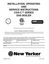
a supply to system
b return from system
c combustion air inlet
d fl ue outlet
e gas valve
f pressure/temperature gauge
g relief valve (not visible)
h air vent connection
i fl ame rollout switch
j air inlet box
k pilot burner and bracket
l stainless steel burners
m cast iron boiler sections
n fl ue collector
o junction box
Other boiler components:

Part number 550-110-260/0508
3
GOLD CGs Gas-Fired Water Boiler — Boiler Manual
GOLD CGs Gas-Fired Induced-Draft Water Boiler

Part number 550-110-260/0508
4
GOLD CGs Gas-Fired Water Boiler — Boiler Manual
Contents
Hazard defi nitions
The following defi ned terms are used throughout this manual to bring attention to the presence of hazards of
various risk levels or to important information concerning the life of the product.
Indicates presence of hazards that will cause severe personal injury, death or substantial
property damage.
Indicates presence of hazards that can cause severe personal injury, death or substantial
property damage.
Indicates presence of hazards that will or can cause minor personal injury or property dam-
age.
Indicates special instructions on installation, operation or maintenance that are important but
not related to personal injury or property damage.
How it works ....................................................2–3
Hazard defi nitions ............................................... 4
Please read before proceeding ............................ 5
1 Prepare boiler location ...................................6–11
2 Prepare boiler ...............................................12–13
3 Water piping .................................................14–23
4 Venting & combustion air ................................... 24
5 Gas piping ......................................................... 25
6 Field wiring ....................................................... 26
7 Start-up ........................................................27–29
8 Check-out procedure ......................................... 30
9 Operation .....................................................31–36
10 Service and maintenance .............................37–42
11 Troubleshooting ............................................43–53
12 Replacement parts .......................................54–61
13 Dimensions and ratings ................................62–63

Part number 550-110-260/0508
5
GOLD CGs Gas-Fired Water Boiler — Boiler Manual
Please read before proceeding
Installer
Read all instructions before in-
stalling.
Follow all instructions in
proper order to prevent personal
injury or death.
• Also refer to CGs Venting Supplements.
• Consider piping and installation when determining
boiler location.
• Any claims for damage or shortage in shipment
must be fi led immediately against the transportation
company by the consignee.
User
• This manual is for use only by your qualifi ed
heating installer/service technician.
• Please refer to the User’s Information Manual for
your reference.
• We recommend regular service by a qualifi ed
service technician, at least annually
.
When calling or writing about the boiler— Please have the boiler model number from the
boiler rating label and the CP number from the boiler jacket. You may list the CP number in
the space provided on the Installation and service certifi cate found on page 30.
The boiler contains ceramic fi ber and fi berglass materials. Use care when handling these
materials per instructions on page 64 of this manual. Failure to comply could result in severe
personal injury.
Failure to adhere to the guidelines on this page can result in severe personal injury, death
or substantial property damage.
• Continual fresh makeup water will reduce
boiler life. Mineral buildup in sections reduces
heat transfer, overheats cast iron, and causes
section failure. Addition of oxygen and other
gases can cause internal corrosion. Leaks in
boiler or piping must be repaired at once to
prevent makeup water.
• Do not add cold water to hot boiler. Thermal
shock can cause sections to crack.
Glycol — potential fi re hazard —
All glycol is fl ammable when exposed to high
temperatures. If glycol is allowed to accumulate
in or around the boiler or any other potential
ignition source, a fi re can develop. In order to
prevent potential severe personal injury, death
or substantial property damage from fi re and/or
structural damage:
• Never store glycol of any kind near the boiler
or any potential ignition source.
• Monitor and inspect the system and boiler
regularly for leakage. Repair any leaks im-
mediately to prevent possible accumulation
of glycol.
• Never use automotive antifreeze or ethylene
glycol in the system. Using these glycols can
lead to hazardous leakage of glycol in the
boiler system.
When servicing boiler —
• To avoid electric shock, disconnect electrical supply
before performing maintenance.
• To avoid severe burns, allow boiler to cool before
performing maintenance.
Boiler operation —
• Do not block fl ow of combustion or ventilation air
to boiler.
• Should overheating occur or gas supply fail to shut
off, do not turn off or disconnect electrical supply to
circulator. Instead, shut off the gas supply at a location
external to the appliance.
• Do not use this boiler if any part has been under
water. Immediately call a qualifi ed service techni-
cian to inspect the boiler and to replace any part of
the control system and any gas control that has been
under water.
Boiler water —
• Do not use petroleum-based cleaning or sealing
compounds in boiler system. Water seal deterioration
will occur, causing leakage between sections. This can
result in substantial property damage.
• Do not use “homemade cures” or “boiler patent medi-
cines”. Serious damage to boiler, personnel and/or
property may result.

Part number 550-110-260/0508
6
GOLD CGs Gas-Fired Water Boiler — Boiler Manual
Prepare boiler location —
codes & checklist
1a
Installations must follow these codes:
• Local, state, provincial, and national codes, laws, regulations and ordinances.
• National Fuel Gas Code, ANSI Z223.1–latest edition.
• Standard for Controls and Safety Devices for Automatically Fired Boilers, ANSI/
ASME CSD-1, when required.
• National Electrical Code.
• For Canada only: B149.1 or B149.2 Installation Code, CSA C22.1 Canadian Electri-
cal Code Part 1 and any local codes.
The CGs boiler gas manifold and controls met safe lighting and
other performance criteria when boiler underwent tests specifi ed
in ANSI Z21.13–latest edition.
Before locating the boiler,
check the following:
• Check for nearby connection to:
• System water piping
• Venting connections
• Gas supply piping
• Electrical power
• Check area around boiler. Remove any combustible materials, gasoline and
other fl ammable liquids, or other contaminants
.
• Check for nearby connection to:
• System water piping
• Venting connections
• Gas supply piping
• Electrical power
• Check area around boiler. Remove any combustible materials, gasoline and
other fl ammable liquids, or other contaminants
.
Failure to keep boiler area clear and free of combustible materials,
gasoline and other fl ammable liquids and vapors
can result in
severe personal injury, death or substantial property damage.
• Boiler must be installed so that gas control system components are protected from
dripping or spraying water or rain during operation or service.
• If new boiler will replace existing boiler, check for and correct system problems,
such as:
1. System leaks causing oxygen corrosion or section cracks from hard water
deposits.
2. Incorrectly-sized expansion tank.
3. Lack of antifreeze in boiler water causing system and boiler to freeze and
leak.

Part number 550-110-260/0508
7
GOLD CGs Gas-Fired Water Boiler — Boiler Manual
Prepare boiler location — clearances1b
Figure 2 Required MINIMUM clearances
Figure 1
Recommended
SERVICE clearances
(see WARNING
below)
Recommended SERVICE clearances
(Fig. 1)
1. Provide clearances for cleaning and servicing the boiler and for
access to controls and components. See Figure 1 for recommenda-
tions.
2. Provide at least screwdriver clearance to jacket front panel screws
for removal of front panel for inspection and minor service. If
unable to provide at least screwdriver clearance, install unions and
shutoff valves in system so boiler can be moved for servicing.
Required MINIMUM clearances (Fig. 2)
Never install the boiler in a space with clear-
ances less than the minimum clearances shown
in Figure 2
. Failure to comply can result in severe
personal injury, death or substantial property
damage and reduced boiler life.
1. Hot water pipes: at least ¹⁄₂ inch from combustible material.
2. Single-wall vent pipe: at least 6 inches from combustible mate-
rial.
3. Type B double-wall metal vent pipe: refer to vent manufacturer’s
recommendation for clearances to combustible material.
If any clearance is less than in Figure 1, provide
openings for combustion and ventilation air
located on the wall or door opposite the boiler
FRONT (see Figure 2)
.
These openings must be located as shown in Figure 2 to provide
proper air fl ow around the boiler. The free area of each opening
(after deducting for louvers) must be at least one square inch per
1,000 Btuh
of boiler input. If the building is of unusually tight
construction (see page 10 for defi nition), the air openings must
connect directly to outside or the building must have air openings
to the outside as specifi ed on page 10.
If clearances are equal to or greater than Figure 1, see pages 10
and 11 for location and sizing of combustion air openings.
Failure to comply can result in severe personal injury, death or
substantial property damage and reduced boiler life.
Flooring
The CGi boiler is approved for installation on combustible
fl ooring, but must never be installed on carpeting.
Do not install boiler on carpeting even
if foundation is used. Fire can result,
causing severe personal injury, death
or substantial property damage.
Foundation
1. Provide a solid brick or minimum 2-inch thick concrete
foundation pad if any of the following is true:
• fl oor can become fl ooded.
• the boiler mounting area is not level.
2. Minimum dimensions are
25” length by:
Minimum foundation width
CGs-3 15” CGs-5 21”
CGs-4 18” CGs-6 24”
Residential garage installations
Take the following special precautions when installing the
boiler in a residential garage. If the boiler is located in a
residential garage, per ANSI Z223.1:
• Mount the boiler a minimum of
18 inches above the
fl oor
of the garage to assure the burner and ignition
devices will be no less than 18 inches above the fl oor.
• Locate or
protect the boiler so it cannot be damaged
by a moving vehicle.

Part number 550-110-260/0508
8
GOLD CGs Gas-Fired Water Boiler — Boiler Manual
Prepare boiler location — vent system1c
Failure to follow all instructions can result in fl ue gas spillage and carbon monoxide emissions, causing severe
personal injury or death.
When removing boiler from an
existing common vent system:
At the time of removal of an existing boiler, the fol-
lowing steps shall be followed with each appliance
remaining connected to the common venting system
placed in operation, while the other appliances remain-
ing connected to the common venting system are not
in operation.
a.
Seal any unused openings in the common venting
system.
b.
Visually inspect the venting system for proper
size and horizontal pitch and determine there is no
blockage or restriction, leakage, corrosion or other
defi ciencies which could cause an unsafe condi-
tion.
c.
Test vent system — Insofar as is practical, close all
building doors and windows and all doors between
the space in which the appliances remaining con-
nected to the common venting system are located
and other spaces of the building. Turn on clothes
dryers and any appliance not connected to the com-
mon venting system. Turn on any exhaust fans, such
as range hoods and bathroom exhausts, so they will
operate at maximum speed. Do not operate a sum-
mer exhaust fan. Close fi replace dampers.
d.
Place in operation the appliance being inspected.
Follow the lighting/operating instructions. Adjust
thermostat so appliance will operate continuously.
e.
Test for spillage at draft hood relief opening after
5 minutes of main burner operation. Use the fl ame
of a match or candle.
f. After it has been determined that
each appliance
remaining connected to the common venting system
properly vents when tested as outlined above, return
doors, windows, exhaust fans, fi replace dampers,
and any other gas-burning appliance to their previ-
ous conditions of use.
Any improper operation of common venting system
should be corrected so the installation conforms with
the National Fuel Gas Code, ANSI Z223.1-latest edition.
Correct by resizing to approach the minimum size as
determined using the appropriate tables in Part 11 of
that code. Canadian installations must comply with
B149.1 or B149.2 Installation Code.
CGs special vent system
Vent system
The CGs boiler requires a special vent system, designed
for pressurized venting. Model CGs-3 is rated ANSI
Z21.13 Category IV (pressurized vent, likely to condense
in the vent). Models CGs-4, -5 and -6 are rated Z21.13
Category III (pressurized vent).
You may use any of the vent systems covered by the
CGs Venting Supplements included in the envelope as-
sembly. The CGs vent starter is a special item, designed
only for the CGs boiler, available from each vendor. Do
not attempt to connect the vent to the CGs boiler with
any other means.
DO NOT mix components from
different systems. The vent system
could fail, causing leakage of fl ue
products into the living space.
Vent termination and combustion air
supply
The CGs boiler may be vented through the roof or
through a side wall. Follow the appropriate vent supple-
ment for the vent system chosen. The maximum vent
length depends on boiler size. Refer to the vent supple-
ment to determine acceptable vent length.
Combustion air for the CGs boiler may be from in-
side or ducted directly to the boiler from outside. For
outside air (direct vent installation), two options are
available for the fl ue/air termination. The air supply
must
ALWAYS terminate at the same location as the
fl ue, using either:
1.
Vertical direct vent installation. Obtain the
Weil-McLain Through-Roof or Through-Unused
Chimney
termination kit and supplement. Refer
to Vertical Direct Venting Venting Supplement,
packed with the kit, and to the vent manufacturer’s
instructions for the vent material chosen.
2.
Sidewall direct vent installation. Use the Vent/Air
Intake
termination kit shipped with the boiler. Refer
to CGs Direct Venting: Sidewall & Direct Exhaust
Venting: Vertical or Sidewall
Venting Supplement
shipped with the boiler.
DO NOT COMMON VENT — Do not install the CGs into a common vent with any other appliance. This will
cause fl ue gas spillage or appliance malfunction, resulting in possible severe personal injury, death or substantial
property damage.
Inspect existing chimney before installing boiler. Failure to clean or replace perforated pipe or tile lining will cause
severe personal injury or death.

Part number 550-110-260/0508
9
GOLD CGs Gas-Fired Water Boiler — Boiler Manual
Prepare boiler location — contamination
1d
Table 1 Corrosive or destructive contaminants and likely locations
To prevent potential of severe personal injury or death, check for products or areas listed
below before installing boiler. If any of these contaminants are found:
• remove contaminants permanently
— OR —
• isolate boiler and provide outside combustion air. See national, provincial or local codes
for further information.
Please review the following information on potential
combustion air contamination problems.
Refer to Table 1 for products and areas which may cause
contaminated combustion air.
CONSTRUCTION DUST HAZARD — Airborne particulates, such as drywall dust
or fi berglass dust, will cause blockage of the CGi burners, resulting in carbon monoxide
production, a fi re hazard, or building freeze damage. If the boiler is operated during
construction, you must isolate the boiler air supply to provide clean air for combus-
tion. Follow the instruction manual guidelines for piping intake air. If you are unable
to ensure uncontaminated air in the boiler air intake at all times, you must inspect
the boiler at least once weekly
. When inspecting, clean the burners if necessary using
the procedure given on page 39. Failure to follow these guidelines could result in severe
personal injury, death or substantial property damage.
Products to avoid Areas likely to have contaminants
Spray cans containing chloro/fluorocarbons Dry cleaning/laundry areas and establishments
Permanent wave solutions Swimming pools
Chlorinated waxes/cleaners Metal fabrication plants
Chlorine-based swimming pool chemicals Beauty shops
Calcium chloride used for thawing Refrigeration repair shops
Sodium chloride used for water softening Photo processing plants
Refrigerant leaks Auto body shops
Paint or varnish removers Plastic manufacturing plants
Hydrochloric acid/muriatic acid Furniture refinishing areas and establishments
Cements and glues New building construction
Antistatic fabric softeners used in clothes dryers Remodeling areas
Chlorine-type bleaches, detergents, and cleaning
solvents found in household laundry rooms
Garages with workshops
Adhesives used to fasten building products and
other similar products
Buildings under construction (where air is
contaminated with particulates)
Airborne particulates (drywall dust, fiberglass
particles, road or gravel dust, lint, etc.)

Part number 550-110-260/0508
10
GOLD CGs Gas-Fired Water Boiler — Boiler Manual
Prepare boiler location — air openings1e
Special considerations
Tight construction
ANSI Z223.1 defines unusually tight construction
where:
1. Walls and ceilings exposed to the outside atmo-
sphere have a continuous water vapor retarder with
a rating of 1 perm or less with openings gasketed,
and . . .
2. Weather-stripping has been added on openable
windows and doors, and . . .
3. Caulking or sealants are applied to areas such as
joints around windows and door frames, between
sole plates and fl oors, between wall-ceiling joints,
between wall panels, at penetrations for plumbing,
electrical, and gas lines, and in other openings.
For buildings with such construction, provide air open-
ings into the building from outside, sized per the ap-
propriate case in Figure 3 if appliances are to use inside
air for combustion and ventilation.
Exhaust fans and air movers
The appliance space must never be under a negative
pressure unless all appliances are installed as direct vent.
Always provide air openings sized not only to the dimen-
sions required for the fi ring rate of all appliances, but
also to handle the air movement rate of the exhaust fans
or air movers using air from the building or space.
Motorized air dampers
If the air openings are fi tted with motorized dampers,
electrically interlock the damper to:
• Prevent the boiler from fi ring if the damper is not
fully open.
• Shut the boiler down should the damper close dur-
ing boiler operation.
To accomplish this interlock, wire an isolated contact
(proving the damper open) in series with the thermo-
stat input to the boiler. The boiler will not start if this
contact is open, and will shut down should it open
during operation.
Combustion air options
✷
Using inside air — direct exhaust vent
The CGs boiler can use inside air if no contaminants are present in the
boiler space. If contaminants are likely to be present, install the CGs boiler
as a direct vent appliance, using the appropriate vent supplement and the
instructions in this manual.
Using outside air — direct vent
Combustion air can be ducted directly from outside to the CGs boiler
air intake fi tting. This method is defi ned as direct vent (also referred to
as sealed combustion). Refer to the appropriate vent supplement and the
instructions in this manual. Two options are available: sidewall or vertical
direct vent. Each requires a special vent component kit.
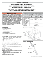
Sizing air openings
✷
Air openings provide for ventilation (as well as combustion air) to prevent
overheating of the boiler controls and boiler space. Air is also needed for
other appliances located in the same space.
Use
Figure 3, page 11, selecting the appropriate installation conditions.
Note that the sizing given in Figure 3 applies only to CGs installations with
clearances no smaller than shown in Figure 1, page 7 of this manual.
For smaller clearances, regardless of how the air openings are arranged, two
openings providing free area of 1 square inch per 1,000 Btuh input of all
appliances in the space are required.
Air openings must be sized to handle all appliances and
air movers (exhaust fans, etc.) using the air supply.
The sizing given in Figure 3 is based on the National Fuel Gas Code, ANSI
Z223.1, allowing adequate air opening for gravity-vented gas appliances
(Category I). The CGs boiler is rated Category III or IV (pressurized vent),
and has different requirements for combustion and ventilation air, refl ected
by the special sizing instructions given in Figure 3. The air openings recom-
mended in Figure 3 will allow adequate ventilation and
combustion air provided the boiler room is not sub-
jected to negative pressure due to exhaust fans or other
mechanical ventilation devices. Refer to the National
Fuel Gas Code for dealing with other conditions.
Louver allowance
The free area of openings means the area after reduc-
tion for any installed louvers or grilles
. Be sure to
consider this reduction when sizing the air openings.
Combustion air opening location and sizing
requirements depend on the clearances around
the boiler.
Check the boiler placement compared to
Figure 1, page 7.
If all clearances are at least equal to Figure 1,
page 7
, apply the sizing and placement of openings
given on pages 10 and 11.
If ANY clearance is less than Figure 1, page 7,
you must provide air openings sized and located
as shown in Figure 2, page 7. DO NOT apply the
sizing and location information shown on page 10
or 11. The Figure 2 air openings are required even if
the boiler is direct vented (outside air piped to the
boiler air intake as described in this manual). These
openings ensure adequate air circulation around the
boiler for cooling, even if the boiler does not use
inside air for combustion.
✷

Part number 550-110-260/0508
11
GOLD CGs Gas-Fired Water Boiler — Boiler Manual
Figure 3 Sizing air openings for CGs installations ✷

Part number 550-110-260/0508
12
GOLD CGs Gas-Fired Water Boiler — Boiler Manual
Place boiler/crate near
position
1. Leave boiler in crate and on pallet until installation
site is ready.
2. Move entire crate and pallet next to selected loca-
tion.
3. Remove crate.
4. Remove boiler from pallet.
Do not drop boiler or bump jacket
on fl oor or pallet. Damage to boiler
can result.
a. Tilt left side of boiler up and place a board
under left legs.
b. Tilt boiler the other way and place a board
under right legs.
c. Slide boiler backward off pallet and into posi-
tion.
5. Check level.
a. Shim legs, if necessary.
b. Do not alter legs.
Prepare boiler — placement & setup2a
Table 2 Manifold orifi ce sizing
Inspect orifi ces and burners
1. Remove front jacket door. Remove inlet air box top
panel (see Figure 27, item 13, page 56).
2. Check for correctly-sized manifold orifi ces. See
Table 2 for sizing. (The orifi ce size is stamped on
the orifi ce spud barrel.)
Correctly-sized manifold orifices
must be used. Failure to do so will
result in severe personal injury,
death or substantial property dam-
age.
3. Reinstall inlet air box top panel.
Orifi ce replacement procedure
(when required)
1. Remove the screws securing the inlet air box top
panel.
2. Remove inlet air box top panel and inspect the fi ber
gasket. Verify the gasket is in good condition and can
seal around the complete perimeter of the air box.
Replace the gasket if necessary.
3. Using a
7
/
16
” open-end wrench, remove the burner
orifi ces from the manifold.
4. Apply a small amount of pipe dope to each of the
new orifi ces and install in the manifold using a
7
/
16
”
open-end wrench. Make sure the orifi ces are aligned
correctly, not cross-threaded in the manifold tap-
pings.
Use only pipe dope compatible with
propane gas, even if boiler is to be
operated on natural gas. Failure to
comply could result in severe per-
sonal injury, death or substantial
property damage.
5. Carefully replace the inlet air box top panel, making
sure the gasket is in place will seal all around the
perimeter.
6. Follow the check-out procedure, Section
8 page 30,
to assure the boiler is now operating properly after
orifi ces are replaced.
Location Natural gas Propane gas
U. S.
0-2,000 ft over 2,000 ft 0-2,000 ft over 2,000 ft
2.70 mm (Note 1) 1.65 mm (Note 1)
Canada
0-2,000 ft 2,000-4,500 0-2,000 ft 2,000-4,500
2.70 mm #38 1.65 mm #53
Note 1:
For elevations above 2,000 feet, contact your local Weil-McLain sales office for details.
Inlet air box top panel must be in
position during boiler operation.
Failure to do so could result in
severe personal injury, death or
substantial property damage.

Part number 550-110-260/0508
13
GOLD CGs Gas-Fired Water Boiler — Boiler Manual
Prepare boiler — pressure test2b
Hydrostatic pressure test
Pressure test boiler before attaching water or gas piping
(except as noted below) or electrical supply.
Prepare boiler for test
1. Remove the shipping nipple (from CGs supply tap-
ping) and remove the boiler relief valve. Temporarily
plug the relief valve tapping with a ¾” NPT pipe
plug.
2. Remove 1¼” nipple, reducing tee and drain valve
from circulator hardware and pressure/temperature
gauge carton. Install in boiler return connection as
shown on page 3 and
Figure 29, page 58. Install
circulator on either the return or supply.
3. Remove 1¼” nipple, 1¼” x 1¼” x ½” tee and pres-
sure/temperature gauge from circulator hardware
and pressure/temperature gauge carton. Pipe to
boiler supply connection as shown on page 3 and
Figure 29, page 58. (Use pipe dope sparingly.)
4. Connect a hose to boiler drain valve, the other end
connected to a fresh water supply. Make sure hose
can also be used to drain boiler after test.
5. Connect a nipple and shutoff valve to system supply
connection on the 1¼” tee. This valve will be used
to bleed air during the fi ll. (Valve and nipple are not
included with boiler.)
6. Connect a nipple and shutoff valve to system re-
turn connection (at circulator fl ange if circulator
installed on return). This valve will be used to bleed
air during the fi ll. (Valve and nipple are not included
with boiler.)
Fill and pressure test
1. Open the shutoff valves you installed on supply and
return connections.
2. Slowly open boiler drain valve and fresh water sup-
ply to fi ll boiler with water.
3. When water fl ows from shutoff valves, close boiler
drain valve.
4. Close shutoff valves.
5. Slowly reopen boiler drain valve until test pressure
on the pressure/temperature gauge reaches no more
than:
•
45 psig for boilers with 30 psig relief valve.
•
75 psig for boilers with 50 psig relief valve.
6.
Test for no more than 10 minutes at:
• 45 psig for boilers with 30 psig relief valve.
• 75 psig for boilers with 50 psig relief valve.
Do not leave boiler unattended.
A cold water fi ll could expand and
cause excessive pressure, resulting
in severe personal injury, death or
substantial property damage.
7. Make sure constant gauge pressure has been main-
tained throughout test. Check for leaks. Repair if
found.
Leaks must be repaired at once.
Failure to do so can damage boiler,
resulting in substantial property
damage.
Do not use petroleum-based clean-
ing or sealing compounds in boiler
system. Severe damage to boiler
will occur, resulting in substantial
property damage.
Drain and remove fi ttings
1. Disconnect fi ll water hose from water source.
2. Drain boiler at drain valve or out hose, whichever
provides best access to drain. Remove hose after
draining if used to drain boiler.
3. Remove nipples and valves unless they will remain
for use in the system piping.
4. Remove plug from relief valve tapping. See page 14
to replace relief valve.

Part number 550-110-260/0508
14
GOLD CGs Gas-Fired Water Boiler — Boiler Manual
Water piping —
general information
3a
Table 3 Water pipe size (based on 20°F rise)
General piping information
If installation is to comply with ASME or Canadian requirements, an ad-
ditional high temperature limit is needed. Install control in supply piping
between boiler and isolation valve. Set second control to minimum 20°F
above setpoint of fi rst control. Maximum allowable setpoint is 240°F. See
Section 9b, page 32 for wiring.
A low water cutoff device is required when boiler is installed above ra-
diation level or by certain state or local codes or insurance companies. Use
low water cutoff designed for water installations. Electrode probe-type is
recommended. Purchase and install in tee in supply piping above boiler.
Use backfl ow check valve in cold water supply as required by local
codes.
Pressure/temperature gauge
Install pressure/temperature gauge in tee on supply piping (as shown in
drawing on page 3).
Relief valve
Install relief valve vertically in ¾” tapping on side of boiler. See Figure 4 or 5,
page 15, and the tag attached to the relief valve for manufacturer’s instructions.
Circulator
The circulator is shipped loose (wiring pre-attached to
boiler) to allow you to locate it either in the return or
supply piping, as desired. See page 3 for a typical instal-
lation. Pipe the expansion tank to the suction side of the
circulator whenever possible. Install an air separator in
the supply piping. Connect the expansion tank to the air
separator only if the separator is on the suction side of
the circulator. Always install the system fi ll connection
at the same point as the expansion tank connection to
the system. Figures 4 and 5, page 15, show typical near-
boiler piping connections.
System water piping
See Figure 4 (diaphragm-type or bladder-type expan-
sion tank) or Figure 5 (closed-type expansion tank) on
page 15, and Table 3 below, for near-boiler and single-
zone systems designed for return water at least 130°F.
See pages 16-17 to complete multiple-zone piping or
pages 18-23 to complete piping for radiant heating
systems or converted gravity systems (large-volume
systems originally designed for circulation by natural
convection rather than a pump).
Chillers or air handling units:
Install boiler such that —
• Chilled medium, if used, is piped in parallel with
heating boiler. Use appropriate valves to prevent
chilled medium from entering boiler. Consult
I=B=R Installation and Piping Guides.
• If boiler is connected to heating coils located in
air handling units where they can be exposed to
refrigerated air, use fl ow control valves or other au-
tomatic means to prevent gravity circulation during
cooling cycle. Circulation of cold water through the
boiler could result in damage to the heat exchanger,
causing possible severe personal injury, death or
substantial property damage.
To avoid water damage or scalding due to relief valve
operation:
• Discharge line must be connected to relief valve outlet and run to a
safe place of disposal
. Terminate the discharge line to eliminate
possibility of severe burns should the valve discharge.
• Discharge line must be as short as possible and be the same size as
the valve discharge connection
throughout its entire length.
• Discharge line must pitch downward from the valve and terminate
at least 6” above the fl oor drain where any discharge will be clearly
visible.
• The discharge line shall terminate plain, not threaded, with a mate-
rial serviceable for temperatures of 375°F or greater.
• Do not pipe the discharge to any place where freezing could
occur.
• No shutoff valve shall be installed between the relief valve and boiler,
or in the discharge line. Do not plug or place any obstruction in the
discharge line.
• Failure to comply with the above guidelines could result in failure of
the relief valve to operate, resulting in possibility of severe personal
injury, death or substantial property damage.
• Test the operation of the valve after fi lling and pressurizing system
by lifting the lever. Make sure the valve discharges freely. If the valve
fails to operate correctly, replace it with a new relief valve.
Boiler
model
number
To
system
From
system
CGs-3/4/5 1" 1"
CGs-6 1 ¼" 1 ¼"
Note: The boiler supply and return connections, the return/
drain tee and the supply/gauge tee supplied with the
boiler are 1¼” NPT. One of the circulator flanges sup-
plied with the boiler is 1¼”. The other circulator flange
is the size of the recommended system piping shown
above.

Part number 550-110-260/0508
15
GOLD CGs Gas-Fired Water Boiler — Boiler Manual
Water piping — single-zone system3b
Figure 4 Diaphragm- or bladder-type expansion tank
Piping to single-zone system
See Table 3 for piping sizes.
Figure 5 Closed-type expansion tank
Piping to single-zone system
See Table 3 for piping sizes.
Diaphragm-type or bladder-
type expansion tank (Figure 4)
1. Ensure expansion tank size will handle boiler and
system water volume and temperature. Tank must
be located in boiler return piping as close to boiler
as possible, before inlet side of circulator. See tank
manufacturer’s instructions for details.
2. Install an
automatic air vent in air vent tapping as
shown.
Closed-type expansion tank
(Figure 5)
1. Ensure expansion tank size will handle boiler and
system water volume and temperature. See tank
manufacturer’s instructions for details.
2. Connect tank to ½” NPT tapping located behind
supply outlet, using ½” NPT piping. Pitch any
horizontal piping up towards tank 1 inch per 5 feet
of piping.
Undersized expansion tanks cause system water to be lost from relief valve and makeup water
to be added through fi ll valve. Eventual section failure can result.
Use Figure 4 or Figure 5 only for single-zone systems designed for return water at least 130°F.
For systems with low return water temperature possible, such as converted gravity systems
and radiant heating systems, refer to the special piping suggestions of pages 18-23. Failure to
prevent low return water temperature to the boiler could cause corrosion of the boiler sections
or burners, resulting in severe personal injury, death or substantial property damage.

Part number 550-110-260/0508
16
GOLD CGs Gas-Fired Water Boiler — Boiler Manual
Water piping — multiple zones3c
Piping multiple zones
Follow instructions on pages 14 and 15 to install near-
boiler or single-zone piping. (Also refer to Piping for
radiant heating systems or converted gravity sys-
tems
, below, if applicable.)
See Figure 6 or Figure 7, page 17, to complete instal-
lation.
Zoning with circulators (Figure 6)
(return temp over 130°F)
1. Size each circulator to individual circuit require-
ments.
2. Do not install circulator on boiler (except for pri-
mary/secondary piping).
3. Install isolation (balancing) valves to adjust fl ow to
distribute heat to all zones.
4. Install and wire a separate relay for each zone cir-
culator.
Zoning with zone valves (Figure 7)
(return temp over 130°F)
1. Install isolation (balancing) valves to adjust fl ow to
distribute heat to all zones.
2. Provide a separate 24-volt transformer to power the
zone valves. Size the transformer to handle the total
rated load of all connected zone valves.
Piping for radiant heating
systems or converted gravity
systems
Converted gravity (or steam) systems
Whenever possible, use the primary/secondary piping
shown in Figures 8 or 9 on page 19. This piping design
allows changing boiler fl ow rate without affecting pri-
mary circuit fl ow rate.
If Figures 8 or 9 cannot be used, use the boiler-bypass
piping shown in Figure 10 or Figure 11 on page 21. You
can also use the piping shown in Figure 12 on page 23
(system-bypass), if the reduced fl ow rate in the heating
system will not cause heat distribution problems.
Failure to prevent low return water
temperature to the boiler could
cause corrosion of the boiler sec-
tions or burners, resulting in severe
personal injury, death or substantial
property damage.
Radiant heating systems
Preferably, use primary/secondary piping, as shown
in Figures 8 or 9 on page 19. Alternatively, use the
method of either Figure 10 or Figure 11 on page 21.
Do not use the piping of Figure 12 (system-bypass),
because this method does not control radiant system
supply temperature.
If radiant system tubing has no oxygen barrier, a heat
exchanger
must be used.
Radiant heating system piping should include a means of regulating the boiler return water
temperature and the system supply temperature (such as provided by an injection pumping
control). Boiler return water temperature will be adequately controlled using the methods
shown in this manual provided the system supply temperature is relatively constant.
DO NOT apply the methods in this manual if the system is equipped with an outdoor reset
control
. Instead, provide controls and piping which can regulate the boiler return water
temperature at no less than 130°F regardless of system supply temperature. Contact your
Weil-McLain representative for suggested piping and control methods. Failure to prevent
cold return water temperature to the boiler could cause corrosion damage to the sections
or burners, resulting in possible severe personal injury, death or substantial property
damage.

Part number 550-110-260/0508
17
GOLD CGs Gas-Fired Water Boiler — Boiler Manual
Figure 6 Zoning with circulators
— return water 130°F or higher.
Figure 7 Zoning with zone valves
— return water 130°F or higher.
1 Boiler isolation (balancing)
valves
2 Flow/check valve
3 System or zone circulator
5 Zone valve
6 Drain valve
9 Relief valve
10 Automatic air vent (with diaphragm-type expansion tank), or connect
to tank fi tting (closed-type expansion tank). DO NOT use an automatic
air vent when using closed-type expansion tank. It would allow air to
leave the system, causing waterlogging of the expansion tank.
11 Fill valve
12 Diaphragm-type or bladder-type expansion tank, if used (For closed-
type expansion tank, pipe from top of air separator to tank fi tting as in
Figure 5, page 15.)
13 Air separator and automatic vent, if used (Note that the fi ll valve must
always be connected to the expansion tank, regardless of location of
expansion tank circulator or air separator.
3c Water piping — multiple zones (continued)
For systems with possible low return-water temperature (such as converted gravity systems,
radiant heating systems and heat pump systems), refer to the special piping suggestions of
Figures 8 - 12, as applies. Failure to prevent sustained low return water temperature to the
boiler could cause corrosion of the boiler sections, resulting in severe personal injury, death
or substantial property damage.

Part number 550-110-260/0508
18
GOLD CGs Gas-Fired Water Boiler — Boiler Manual
Piping — low temp systems3d
Failure to prevent low return water temperature to the boiler could cause corrosion of
the boiler sections or burners, resulting in severe personal injury, death or substantial
property damage.
Radiant heating system piping should include a means of regulating the boiler return
water temperature
and the system supply temperature (such as provided by an injec-
tion pumping control
).
Boiler return water temperature will be adequately controlled using the methods shown
in this manual provided the system supply temperature is relatively constant.
DO NOT apply the methods of this manual if the system is equipped with an outdoor
reset control.
Instead, provide controls and piping which can regulate the boiler re-
turn water temperature
at no less than 130°F regardless of system supply temperature.
Contact your Weil-McLain representative for suggested piping and control methods.
Failure to
prevent cold return water temperature to the boiler could cause corrosion
damage to the sections or burners, resulting in possible severe personal injury, death or
substantial property damage.
Primary/secondary (preferred)
bypass piping method
Primary/secondary bypass piping is preferred because
the flow rate and temperature drop in the heating
circuit(s) is determined only by the heating circuit
circulator(s). So adjustment of the bypass valves in
the boiler circuit will not cause a change in the heating
circuit rate and temperature distribution.
Figures 8 and 9, page 19, show suggested bypass ar-
rangements using primary/secondary bypass piping
(preferred) for low temperature systems such as radiant
heating systems
or converted gravity systems. For
alternatives, see pages 20 through 23.
The bypass valves in
Figures 8 and 9 (items 7a and 7b)
provide mixing of hot boiler outlet water with cooler
system return water — set to assure a minimum return
water temperature (at least 130°F) to the boiler. Set the
valves as explained below.
Temperature gauges
Gauge 4a is suggested, but optional on any system.
Gauge
4b is optional on converted gravity systems,
but required on radiant heating systems — to display
the water temperature being supplied to the radiant
tubing.
Gauge
8 is required on all systems to assure the return
water temperature is accurately set for a minimum of
130°F. If this gauge is not available however, adjust the
valves such that the boiler-mounted temperature/pres-
sure gauge reads at least 150°F when the system return
water is cold (approximately 60°F water temperature).
Valve adjustment
(Figures 8 and 9 only)
1. Set the valves while the system is cool, setting for the
coldest expected water temperature (usually 60°F
since the system will often drop to room tempera-
ture between cycles).
2. Start with valve
7a fully closed and 7b fully open.
3. Gradually open valve
7a while closing valve 7b until
the temperature at gauge 8 reads 130°F when gauge
4a reads 60°F.
4. Note that valve
7a regulates the amount of hot wa-
ter from the boiler supply which mixes with return
water. Valve 7b regulates the amount of system water
fl owing through the boiler secondary loop.

Part number 550-110-260/0508
19
GOLD CGs Gas-Fired Water Boiler — Boiler Manual
1 Boiler isolation (balancing) valves
2 Flow/check valve
3 System or zone circulator
4 System temperature gauges
5 Zone valve
6 Drain valve
7 System temperature valves (see instruc-
tions to the left for adjusting valves)
8 Blend temperature gauge
9 Relief valve
10 Automatic air vent (with diaphragm-type expansion tank), or
connect to tank fi tting (closed-type expansion tank). DO NOT
use an automatic air vent when using closed-type expansion
tank. It would allow air to leave the system, causing waterlog-
ging of the expansion tank.
11 Fill valve
12 Diaphragm-type or bladder-type expansion tank, if used (For
closed-type expansion tank, pipe from top of air separator to
tank fi tting as in Figure 5, page 15.)
13 Air separator and automatic vent, if used (Note that the
fi ll valve must always be connected to the expansion tank,
regardless of location of expansion tank, circulator or air
separator.)
Figure 8 Primary/secondary piping
Zoning with circulators
Figure 9 Primary/secondary piping
Zoning with zone valves
3d Piping — low temp systems (continued)

Part number 550-110-260/0508
20
GOLD CGs Gas-Fired Water Boiler — Boiler Manual
Failure to prevent low return water temperature to the boiler could cause corrosion of
the boiler sections or burners, resulting in severe personal injury, death or substantial
property damage.
Radiant heating system piping should include a means of regulating the boiler return
water temperature
and the system supply temperature (such as provided by an injec-
tion pumping control
).
Boiler return water temperature will be adequately controlled using the methods shown
in this manual provided the system supply temperature is relatively constant.
DO NOT apply the methods of this manual if the system is equipped with an outdoor
reset control.
Instead, provide controls and piping which can regulate the boiler re-
turn water temperature
at no less than 130°F regardless of system supply temperature.
Contact your Weil-McLain representative for suggested piping and control methods.
Failure to
prevent cold return water temperature to the boiler could cause corrosion
damage to the sections or burners, resulting in possible severe personal injury, death or
substantial property damage.
3d Piping — low temp systems (continued)
BOILER-bypass piping
method
This piping method (Figures 10 and 11, page 21) is
called a boiler-bypass because part of the circulator
fl ow is bypassed around the boiler (through valve 7a).
This method reduces the fl ow rate throughout the boiler,
in order to raise the average water temperature in the
boiler enough to prevent fl ue gas condensation. Boiler-
bypass piping is effective for some boilers — including
the CGs — provided the fl ow rates are adjusted accord-
ing to the instructions following.
Figures 10 and 11 are alternative piping suggestions
for converted gravity (large water content or steam
systems) or radiant heating system — for use when
primary/secondary piping can’t be applied. (Figure 12,
page 23, is another alternative, using system bypass in
place of boiler-bypass piping. Figure 12 however, is
not suitable for radiant heating applications because it
does not protect the radiant system from possible high
water temperature.)
Boiler-bypass piping keeps system fl ow rate as high as
possible and temperature drop as low as possible, help-
ing to equalize the building heat distribution.
Temperature gauges
Gauge 4a is optional if the bypass valves will be ad-
justed using cold (or room temperature) return water
to the boiler. (When setting the valves without gauge
4a installed — using cold or room temperature water
— assume the return water temperature to be 60°F. Set
the valves so gauge 8 reads at least 120°F.
Gauge
4b is optional on converted gravity systems,
but required on radiant heating systems — to display
the water temperature being supplied to the radiant
tubing.
Gauge
8 is required on all systems to assure reliable
adjustment of the bypass valves. The boiler-mounted
temperature/pressure gauge can be used if a separate
temperature gauge is not installed.
Valve adjustment
1. Start with valve 7a fully closed and 7b fully open.
2. Gradually open valve
7a while closing valve 7b
until the temperature at gauge 8 reads 60 °F higher
than gauge 4a. A minimum 60°F temperature rise
through the boiler assures a low enough fl ow rate
and high enough average temperature to prevent
condensation even with low system return water
temperature.
3. Valve
7a regulates the system fl ow rate, while valve
7b regulates the boiler fl ow rate.
4. The boiler-mounted temperature/pressure gauge
may be used in place of a separate gauge
8.
/