Page is loading ...

GAS-FIRED, DIRECT VENT,
CONDENSING, HOT WATER BOILER
INSTALLATION, OPERATION &
MAINTENANCE MANUAL
An ISO 9001-2008 Certified Company
DUNKIRK BOILERS
85 Middle Rd.
Dunkirk, NY 14048
www.dunkirk.com
P/N# 14683301, Rev. C [12/2010]

2
These instructions
must be afxed on or
adjacent to the boiler.
90-50-100 GAS-FIRED BOILER
Model No.
90-50
90-75
90-100
!
CAUTION
Read all instructions carefully before starting
the installation.
Save this manual for reference.
!
WARNING
Improper installation, adjustment, alteration,
service, or maintenance can cause injury or
property damage. Refer to this manual. For
assistance or additional information consult a
qualied installer, service agency, or the gas
supplier.
H

3
TABLE OF CONTENTS
!
DANGER
Indicates an imminently hazardous situation
which, if not avoided, WILL result in death,
serious injury or substantial property damage.
WARNINGS AND SAFETY SYMBOLS
IMPORTANT: THIS MANUAL MUST BE KEPT NEAR THE BOILER FOR FUTURE REFERENCE!!
!
WARNING
Indicates an imminently hazardous situation
which, if not avoided, may result in death,
serious injury or substantial property damage.
!
CAUTION
Indicates an imminently hazardous situation
which, if not avoided, may result in injury or
property damage.
NOTICE
Indicates information which should be
followed to ensure proper installation and
operation.
H
Warnings and Safety Symbols ....................................................................................................... 3
Introduction ................................................................................................................................ 4
Boiler Ratings & Capacities ........................................................................................................... 5
Boilers For Use At High Altitude ..................................................................................................... 6
Rules For Safe Installation And Operation ....................................................................................... 8
Before Installing The Boiler ........................................................................................................... 8
Placing The Boiler .......................................................................................................................11
Near Boiler Piping .......................................................................................................................12
Combustion Air and Vent Pipe ......................................................................................................19
Gas Supply Piping .......................................................................................................................24
Electrical Wiring .........................................................................................................................26
Controls and Accessories .............................................................................................................30
Water Treatment & Freeze Protection ............................................................................................32
Start Up ....................................................................................................................................34
Operating Instructions .................................................................................................................35
To Turn Off Gas To Appliance ........................................................................................................35
Check Out Procedure and Adjustment ...........................................................................................36
Installation and Check-Out Certicate............................................................................................40
Maintenance And Cleaning ...........................................................................................................41
Detailed Sequence Of Operation ...................................................................................................44
Troubleshooting ..........................................................................................................................47
Differential Air Pressure Switch Check ...........................................................................................55

4
INTRODUCTION
Figure 1 - Boiler Dimensions
is appliance is a gas-red direct vent hot water boiler with cast
aluminum boiler sections. A revolutionary cast aluminum heat
exchanger means better heat transfer and thermal storage than
similarly sized cast iron boilers, which results in higher eciency.
e heating system water absorbs large amounts of heat from the
cast aluminum heat exchanger, cooling the ue gases and causing
condensation. Sealed combustion, premix gas burner, and low ame
temperature means drastically reduced CO and NOx emissions,
which contribute to a cleaner and healthier environment.
is appliance, unlike normal residential atmospheric and induced
dra units, takes its combustion air directly from the outdoors
(sealed combustion) and does not compete with building occupants
for fresh air. Sealed combustion (also known as “direct vent”) is the
safest and best way to obtain plenty of clean combustion air. e
induced dra fan draws in the outside combustion air, then takes the
cooler ue gases from the boiler unit and provides a positive removal
of the ue gases from the building through inexpensive and readily
available PVC and CPVC pipes.
NOTICE
IMPORTANT: Read the following instructions
COMPLETELY before installing!

5
TABLE #1 – SEA LEVEL RATINGS – NATURAL AND PROPANE GASES
Model
Input
*(MBH)
++ Heating Capacity
*(MBH)
Net I=B=R Rating
*(MBH)
Shipping
Weight (lbs.)
Flue Dia.
90-50 50 45 39 220 2” CPVC & PVC
90-75 75 68 59 220 2” CPVC & PVC
90-100 100 90 78 220 2” CPVC & PVC
* 1 MBH = 1,000 Btuh Btuh = British ermal Units Per Hour
BOILER RATINGS & CAPACITIES
ese low pressure gas-red hot water boilers are design certied
by CSA International for use with natural and propane gases. e
boilers are constructed and hydrostatically tested for a maximum
working pressure of 50 psig (pounds per square inch gage) in
accordance with A.S.M.E. (American Society of Mechanical
Engineers) Boiler and Pressure Vessel Code Section IV Standards for
heating boilers.
++ AFUE (Annual Fuel Utilization Eciency) and Heating Capacity
is based on the D.O.E. (Department of Energy) test procedure.
e Boilers are certied in accordance with ANSI (American
National Standards Institute) Z21.13 standards as gas-red, direct
vent, condensing, hot water boilers.
e Heating Capacity indicates the amount of heat available aer
subtracting the losses up the stack. Most of this heat is available to
heat water. A small portion is heat from the jacket and surfaces of
the boiler, and it is assumed that this heat stays in the structure. e
Net I=B=R Rating represents the portion of the remaining heat that
can be applied to heat the radiation or terminal units (i.e. nned
tube baseboard, cast iron radiators, radiant oor, etc.). e dierence
between the Heating Capacity and the Net I=B=R Rating, called the
piping and pickup allowance, establishes a reserve for heating the
volume of water in the system and osetting heat losses from the
piping.
e Net I=B R Ratings shown are based on a piping and pickup
factor of 1.15 in accordance with the I=B=R Standard as published
by the Hydronics Institute. e Net I=B=R Rating of the boiler
selected should be greater than or equal to the calculated peak
heating load (heat loss) for the building or area(s) served by the
boiler and associated hot water heating systems. e manufacturer
should be consulted before selecting a boiler for installations having
unusual piping and pickup requirements.
e boilers are factory equipped for operation at altitudes ranging
from 0-2,000 feet above sea level. For use of these boilers at altitudes
above 2,000 feet above sea level, the gas input ratings (MBH)
automatically reduced.

6
TABLE #1: SERIES 90 NATURAL GAS
SERIES 90-50
Stock Factory Btu Value of Natural Gas++
Settings 750 850 950 1000 1050
Altitude in Ft. 0-5,000 5,000-10,000
Normal Input (MBH) 50 – – – – –
Manifold Pressure In W.C. 2.5 4 4 3.5 2.5 2.5
Orice 43331094 43331094
SERIES 90-75
Stock Factory Btu Value of Natural Gas++
Settings 750 850 950 1000 1050
Altitude in Ft. 0-5,000 5,000-10,000
Normal Input (MBH) 75 – – – – –
Manifold Pressure In W.C. 2.5 3.5 3.5 2.5 2.5 2.5
Orice 43331092 43331092
SERIES 90-100
Stock Factory Btu Value of Natural Gas++
Settings 750 850 950 1000 1050
Altitude in Ft. 0-5,000 5,000-10,000
Normal Input (MBH) 100 – – – – –
Manifold Pressure In W.C. 2.5 3.5 3.5 2.5 2.5 2.5
Orice 43331090 43331090
++Contact local gas utility or distributor for Btu value of gas.
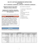
BOILERS FOR USE AT HIGH ALTITUDE
e boilers (with the exception of the 90-75 LP product) are factory
equipped for operation at altitudes ranging from 0-10,000 feet above
sea level. No changes to the factory settings are required for instal-
lations from 0-5,000 feet above sea level. For altitudes from 5,000-
10,000 feet above sea level the gas manifold pressure will need to be
adjusted based upon caloric (Btu) value of supply gas (contact local
gas utility or distributor for this value). For specic settings refer to
Table #1 for natural gas applications and
Table #2
for LP gas ap-
plications. Instructions on how to adjust the gas manifold pressure
settings are shown in
Figures 17 & 18
.
Note that 90-75 LP applications for 5,000 - 10,000 feet above sea
level will require an orice change as well as a gas manifold pres-
sure adjustment based upon caloric (Btu) value of supply gas. Refer
to
Table #2
for altitude orice kit part number. For replacing the
orice refer to specic instructions included with the kit.

7
TABLE #2: SERIES 90 PROPANE GAS
SERIES 90-50
Stock Factory Btu Value of LP Gas++
Settings 2300 2350 2400 2450 2500
Altitude in Ft. 0-5,000 5,000-10,000
Normal Input (MBH) 50
– – – – –
Manifold Pressure In W.C. 2.5 3 3 2.5 2.5 2.5
Orice 43331095 43331095
SERIES 90-75*
Stock Factory Btu Value of LP Gas++
Settings 2300 2350 2400 2450 2500
Altitude in Ft. 0-5,000 5,000-10,000
Normal Input (MBH) 75
– – – – –
Manifold Pressure In W.C. 2.5 3.5 3.5 3.5 3 3
Orice 43331093
43331096*
* For model 90-75 LP units only at altitudes above 5,000 ft., install 90-75 High Altitude Orice Kit #550001810. For all other alti-
tudes use factory installed orice.
SERIES 90-100
Stock Factory Btu Value of LP Gas++
Settings 2300 2350 2400 2450 2500
Altitude in Ft. 0-5,000 5,000-10,000
Normal Input (MBH) 100
– – – – –
Manifold Pressure In W.C. 2.5 3 3 3 2.5 2.5
Orice 43331091 43331091
++Contact local gas utility or distributor for Btu value of gas.
BOILERS FOR USE AT HIGH ALTITUDE
NOTICE
For model 90-75 LP units only at altitudes
above 5,000 ft., install 90-75 High Altitude
Orice Kit #550001810*. For all other
altitudes use factory installed orice.

8
Complete all of the following prior to installing the boiler.
Codes
is boiler product is a gas-red, direct vent, condensing boiler and
must be installed to conform to the requirements of the authority
having jursidiction or, in the absence of such requirements:
United States - National Fuel Gas Code (NFPA-54/ANSI Z223.1).
Canada - National Gas and Propane Installation Code, Can/CSA
B149.1.
Where required by the authority having jurisdiction, the installation
must conform to the American Society of Mechanical Engineers
Safety Code for Controls and Safety Devices for Automatically Fired
Boilers, No.CSD-1.
NOTICE
Important - In the state of Massachusetts
this product must be installed by a licensed
plumber or gas tter and the installation must
be in accordance with 248 CMR.
Installers - Follow local regulations with respect to installation of
CO (Carbon Monoxide) Detectors. Follow maintenance recommen-
dations in this manual.
Installation Requirements Specic To e State Of
Massachusetts
For Direct Vent, Mechanical Vent, And
Domestic Hot Water Appliances
For all side wall horizontally vented gas fueled equipment installed
in every dwelling, building or structure used in whole or in part
for residential purposes, including those owned or operated by the
commonwealth and where the side wall exhaust vent termination is
less than seven (7) feet above nished grade in the area of the vent-
ing, including but not limited to decks and porches, the following
requirements shall be satised:
Installation of carbon monoxide detectors: at the time of instal-
1.
lation of the side wall horizontal vented gas fueled equipment,
the installing plumber or gastter shall observe that a hard
wired carbon monoxide detector with an alarm and battery
back-up is installed on the oor level where the gas equipment
is to be installed. In addition, the installing plumber or gastter
shall observe that a battery operated or hard wired carbon mon-
oxide detector with an alarm is installed on each additional level
of the dwelling, building or structure served by the side wall
horizontal vented gas fueled equipment. It shall be the respon-
sibility of the property owner to secure the services of qualied
licensed professionals for the installation of hard wired carbon
monoxide detectors.
Read the entire installation manual before beginning the instal-
1.
lation. Failure to follow these rules for safe installation and
operation and these instructions could cause a malfunction
of the boiler and result in death, serious bodily injury, and/or
property damage.
Check all applicable state and local building codes and util-
2.
ity company requirements before installation. e installation
must conform with these requirements in their entirety. In the
absence of these codes, use NFPA Installation Codes and good
industry practice.
Before servicing the boiler - allow the boiler to cool. Always
3.
shut o any electricity and gas supply connected to the boiler
prior to servicing.
Inspect gas line for leaks.
4.
Be certain gas input rate is correct. Over ring may result in
5.
early failure of the boiler sections. is may cause dangerous
operation. Under ring may result in too much air for the pre-
mix burner causing poor or loss of combustion.
Never vent the products of combustion from this boiler to an
6.
enclosed space. Always vent to the outdoors. Never vent to
another room or to inside a building.
Be sure there is adequate outdoor air supply to boiler for com-
7.
plete combustion.
Follow a regular service and maintenance schedule for ecient
8.
and safe operation.
Keep boiler area clean of debris and free of combustible and
9.
ammable materials.
Proper through the wall or through the roof combustion vent-
10.
ing shall be in accordance with the materials and methods
described in this manual. Installation must comply with local
codes.
is boiler and related hot water heating systems are not do it
11.
yourself items. ey must be installed and serviced by qualied
professionals.
RULES FOR SAFE INSTALLATION AND OPERATION
BEFORE INSTALLING THE BOILER
!
WARNING
This boiler has been equipped for residential
installations. If used for commercial
applications, any additional code requirements
must be adhered to for installation. This may
require additional controls including but not
limited to a low water cut off, a manual reset
high temperature limit, and wiring and/or
piping modications. The manufacturer is not
responsible for any eld installation changes
made to a boiler installation which are not
described or acknowledged in this manual.

9
In the event that the side wall horizontally vented gas A.
fueled equipment is installed in a crawl space or an attic,
the hard wired carbon monoxide detector with alarm and
battery back-up may be installed on the next adjacent oor
level.
In the event that the requirements of this subdivision can
B.
not be met at the time of completion of installation, the
owner shall have a period of thirty (30) days to comply
with the above requirements; provided, however, that dur-
ing said thirty (30) day period, a battery operated carbon
monoxide detector with an alarm shall be installed.
Approved carbon monoxide detectors: each carbon monoxide
2.
detector as required in accordance with the above provisions
shall comply with NFPA720 and be ANSI/UL 2034 listed and
IAS certied.
Signage: a metal or plastic identication plate shall be perma-
3.
nently mounted to the exterior of the building at a minimum
height of eight (8) feet above grade directly in line with the
exhaust vent terminal for the horizontally vented gas fueled
heating appliance or equipment. e sign shall read, in print
size no less than one-half (1/2) inch in size, “gas vent directly
below. Keep clear of all obstructions”.
Inspection: the state or local gas inspector of the side wall
4.
horizontally vented gas fueled equipment shall not approve
the installation unless, upon inspection, the inspector observes
carbon monoxide detectors and signage installed in accordance
with the provisions of 248 CMR 5.08(2)(A)1 through 4.
Product-approved vent/air-intake: a product-approved vent ter-
5.
minal must be used and, if applicable, a product-approved air
intake must be used. Installation shall be in strict compliance
with the manufacturer’s instructions.
Installation instructions: a copy of all installation instructions
6.
for all product approved side wall horizontally vented gas fueled
equipment, all venting instructions, all parts lists for venting
instructions, and/or all venting design instructions shall remain
with the appliance or equipment at the completion of the instal-
lation.
Boiler Sizing
Check to be sure you have selected the boiler with the proper capac-
ity before starting the installation. e I=B=R Rating of the boiler
selected should be greater than or equal to the calculated peak heat-
ing load (heat loss) for the building or area(s) served by the boiler
and associated hot water heating systems. See the table “BOILER
RATINGS AND CAPACITIES” (page 5 of this document).
Heat loss calculations should be based on approved industry meth-
ods.
Considerations For Boiler Location
Before selecting a location for the boiler, the following should be
considered. Each boiler considered.
Supplied with the correct type of gas (natural gas or pro-•
pane).
Connected to a suitable combustion air intake piping sys-•
tem to supply the correct amounts of fresh (outdoor) air
for combustion, refer to Combustion Air And Vent Pipe
section (near center of this manual) for details.
Connected to a suitable venting system to remove the •
hazardous products of gas combustion, refer to Combus-
tion Air And Vent Pipe section (page 19 of this manual) for
details.
Connected to a suitable hot water heating system.•
Supplied with a suitable electrical supply for all boiler mo-•
tors and controls.
Connected to a properly located thermostat or operating •
control. (not included with boiler)
Placed on level surface (must NOT be installed on carpet-•
ing)
Condensate drain line must be pitched down to oor drain •
or external condensate pump with reservoir at ¼” per foot
(wood frame or blocks may be used to raise boiler).
Locating The Boiler
Select a location which is level, central to the piping systems
1.
served and as close to the vent and air intake terminals as pos-
sible.
Accessibility clearances, if more stringent (i.e. larger clearances)
2.
than required re protection clearances, must be used for the
boiler installation. Accessibility clearances may be achieved
with the use of removable walls or partitions.
e boiler is approved for installation in closets and on com-
3.
bustible oors. is boiler shall NOT be installed on carpeting.
e clearances shown in
4. Table #2
indicate required clearances.
A minimum 1” clearance must be maintained between com-
bustible construction and each of the le, top and back surfaces
of the boiler. A minimum 8” clearance is required on the right
side, to allow room for the inlet air pipe. An 18” clearance must
be maintained at a side where passage is required to access an-
other side for cleaning or servicing, inspection or replacement
of any parts that normally may require such attention. Allow at
least 24” at the front and le side and 8” at the top for servicing.
No clearances are required to venting or combustion air intake
piping.
Equipment shall be installed in a location which facilitates the
5.
operation of venting and combustion air intake piping systems
as described in this manual.
BEFORE INSTALLING THE BOILER

10
TABLE #2 -
Required Clearances
Unit
Combustible Clearance
Inch (mm)
Accessibility, Cleaning, and Servicing
Inch (mm)
Top 1 (25.4) 8 (203.2)
Left Side 1 (25.4) 24 (609.6)
Right Side 8 (203.2) -
Base 1 (25.4) -
Front 1 (25.4) 24 (609.6)
Back 1 (25.4) -
Intake/Vent Piping 0 (0) -
Near Boiler Hot Water Piping 1 (25.4) -
All distances measured from the cabinet of the boiler.
Advise owner of boiler to keep venting and combustion air
6.
intake passages free of obstructions. both the venting and com-
bustion air intake piping systems connected to the outdoors
must permit ow through the piping systems without restric-
tions for the boiler to operate.
e boiler shall be installed such that the automatic gas ignition
7.
system components are protected from water (dripping, spray-
ing, rain, etc.) during operation and service (circulator replace-
ment, condensate trap, control replacement, etc.).
Combustion Air And Vent Pipe Requirements
is boiler requires a dedicated direct vent system. In a direct vent
system, all air for combustion is taken directly from outside atmo-
sphere, and all ue products are discharged to outside atmosphere.
Combustion air and vent pipe connections must terminate together
in the same atmospheric pressure zone, either through the roof
or sidewall (roof termination preferred). See
Figures 9 & 10
(in
Combustion Air And Vent Pipe section of this manual) for required
clearances.
BEFORE INSTALLING THE BOILER
!
CAUTION
Keep boiler area clean of debris and free of
amable and combustible materials, vapors
and liquids.
!
WARNING
When vent pipe is exposed to temperatures below freezing, such as when it passes through an
unheated space or when a chimney is used as a raceway, vent pipe must be insulated with 1/2”
Armaex or equivalent. In extreme cold climate areas, use ¾” Armaex or equivalent.
Combustion air must be clean outdoor air. Combustion air must not be taken from inside structure
because that air frequently is contaminated by halogens, which include uorides, chlorides, phosphates,
bromides and iodides. These elements are found in aerosols, detergents, bleaches, cleaning solvents,
salts, air fresheners, paints, adhesives and other household products.
Locate combustion air inlet as far away as possible from swimming pool and swimming pool pump
house.
All combustion air and vent pipes must be airtight and watertight. Combustion air and vent piping must
also terminate exactly as shown in
Figure 9 or 10
(in Combustion Air And Vent Pipe section, page 19
of this manual).
Vent connections serving appliances vented by natural draft shall not be connected into any portion of
mechanical draft systems operating under positive pressure.
Solvent cements are combustible. Keep away from heat, sparks, and open ame. Use only in well
ventilated areas. Avoid breathing in vapor or allowing contact with skin or eyes.
FAILURE TO FOLLOW THE AFOREMENTIONED WARNINGS COULD RESULT IN FIRE, PROPERTY DAMAGE,
PERSONAL INJURY, OR DEATH.

11
Condensate Drain Requirements
Condensate drain line to be pitched down to oor drain at a mini-
mum of ¼” per foot. An external condensate pump (not furnished)
may be used if oor drain is not available. e condensate pump
must be designed for ue gas condensate application.
BEFORE INSTALLING THE BOILER
NOTICE
1. Condensate trap is built into the boiler, an
external trap is not required and should not
be used.
2. Wood frame or blocks may be used to raise
the boiler to maintain drain pitch or to be
above external condensate pump reservoir.
3. There is a 115 Volt AC receptacle provided
on the service switch junction box which is
located at the boiler right side, to provide
power for an external condensate pump (if
needed).
Foundation Requirements
Boiler must be placed on level surface. Boiler is NOT to be installed
on carpeting.
NOTICE
If boiler is not level condensate drain lines
will not function properly. Adjustable feet are
located on the boiler to make up for minor
surface irregularities or tilt.
Wood frame or blocks may be used to raise
boiler to maintain drain pitch or to be above
external condensate pump reservoir.
Removal of Existing Boiler From Common Vent System
When an existing boiler is removed from a common venting system,
the common venting system is likely to be too large for proper vent-
ing of the appliances remaining connected to it. At the time of re-
moval of an existing boiler, the following steps shall be followed with
each appliance remaining connected to the common venting system
placed in operation, while the other appliances remaining connected
to the common venting system are not in operation.
Seal any unused openings in the common venting system.
1.
Visually inspect the venting system for proper size and hori-
2.
zontal pitch and determine there is no blockage, or restrictions,
leakage, corrosion and other deciencies which could cause an
unsafe condition.
In-so-far as is practical, close all building doors and windows
3.
and all doors between the space in which the appliances remain-
ing connected to the common venting system are located and
other spaces of the building. Turn on clothes dryer and any ap-
pliance not connected to the common venting system. Turn on
any exhaust fans, such as range hoods and bathroom exhaust, so
they will operate at maximum speed. Do not operate a summer
exhaust fan. Close re dampers.
Place in operation the appliance being inspected. Follow the
4.
lighting instructions. Adjust thermostat so appliances will oper-
ate continuously.
Test for spillage at the dra hood relief opening aer 5 minutes
5.
of main burner operation. Use the ame of a match or candle,
or the smoke from a cigarette, cigar or pipe.
Aer it has been determined that each appliance remaining
6.
connected to the common venting system properly vents when
tested as outlined above, return doors, windows, exhaust fans,
re place dampers, and any other gas-burning appliance to their
previous condition of use.
Any improper operation of the common venting system should
7.
be corrected so the installation conforms with the National Fuel
Code, NFPA-54/ANSI -Z223.1 and/or the Natural Gas and
Propane Installation Code, CAN/CSA B149.1.. When resizing
any portion of the common venting system, the common vent-
ing system should be resized to approach the minimum size as
determined using the appropriate tables in Chapter 13 of the
National Fuel Gas Code, NFPA-54/ANSI- Z223.1 and/or the
Natural Gas and Propane Installation Code, CAN/CSA B149.1.
PLACING THE BOILER
e boiler should be placed to provide the most direct connections
to the combustion air, vent and system piping as possible.
Place crated boiler as close to selected location as possible and
uncrate boiler. e uncrated boiler may be moved into position with
an appliance dolly or 2-wheel hand truck. e dolly or hand truck
should be inserted under the le hand side of the boiler. It is possible
to slide the boiler for a short distance on a smooth oor or surface.
NOTICE
Refer to manual section “locating the
boiler” (page 9 of this manual), for required
clearances for servicing and maintenance.

12
When the installation of the boiler is for a new heating system, rst
install all of the radiation units (panels, radiators, baseboard, or tub-
ing) and the supply and return mains. Aer all heating system piping
and components have been installed, make nal connection of the
system piping to the boiler. A hot water boiler installed above radia-
tion level, or as required by the Authority having jurisdiction, must
be equipped with a low water cut o device. A periodic inspection
is necessary for ushing of oat type devices, per low water cut o
manufacturers specic instructions.
Supply And Return Lines
e packaged boiler unit is set up to receive 1 ¼” NPT supply and
return piping from top access. e boiler unit can also be piped from
the le side by turning the supply elbow, and from the rear of the
unit by removing plugs in the rear boiler section.
NEAR BOILER PIPING
!
CAUTION
Copper supply and return piping must NOT be
installed directly into aluminum boiler section
casings due to galvanic corrosion between
dissimilar metals. Iron or steel bushings or
pipe nipples should be used between copper
system piping and boiler to make nal
connection to boiler. Also, the use of dielectric
unions is acceptable. The packaged boiler is
furnished with iron piping in the front boiler
section for the supply and return connections.
Figure 2 - Single Zone Boiler Piping
NOTICE
The circulator pump and isolation valves are
furnished within a carton inside the boiler
cabinet and can be installed at the installer
preferred location.

13
Figure 3 - Multi-zone Boiler Piping With Zone Valves
NEAR BOILER PIPING

14
Figure 4 - Multi-Zone Boiler Piping With Circulators
NEAR BOILER PIPING
NOTICE
When zoning with circulators, the furnished circulator pump should be used as one of the zone pumps.
Each stripped end of the electrical wires for the circulator pump inside the junction box should be taped
or wire nutted to prevent short circuits. Unplug the circulator pump wiring at the integrated boiler
control.

15
Pressure Relief Valve
e boiler is furnished with a factory installed relief valve in the top
of the boiler. Provide ¾” piping from the supplied relief valve to a
local oor drain, but leave an air gap between piping and drain. No
shuto of any description shall be placed between safety relief valve
and the boiler, or on the discharge pipes between such safety valve
and the atmosphere. Installation of the safety relief valve shall con-
form to ANSI/ASME Boiler and Pressure Vessel Code, Section IV.
e manufacturer is not responsible for any water damage.
Expansion Tank And Make-Up Water
Determine required system ll pressure, system design temperature,
and system water content. Boiler contains 2.6 gallons (U.S.). Size
expansion tank accordingly. Consult expansion tank manufacturer
for proper sizing information. Connect properly sized expansion
tank (not furnished) as shown in
Figure 6
for diaphragm type ex-
pansion tank and
Figure 7
for conventional closed type expansion
tanks. For diaphragm type expansion tanks, adjust the tank air pres-
sure to match the system ll pressure. Install air vent (furnished)
as shown for diaphragm type expansion tank system only. Install
make-up water connections as shown per local codes. If a pressure
reducing valve is used, adjust to match the system ll pressure. In
connecting the cold make-up water supply to the boiler, make sure
that clean water supply is available. When the water supply is from a
well or pump, sand strainer should be installed at the pump.
Figure 5 - Single Zone Boiler Piping
NEAR BOILER PIPING

16
Figure 6 - Diaphragm Type Expansion Tank Piping
NEAR BOILER PIPING

17
Figure 7 - Conventional (closed type) Expansion Tank Piping
NEAR BOILER PIPING

18
Condensate Drain Piping
e condensate trap is built into the boiler, an external trap is not
required and should NOT be used.
Provide ½” PVC condensate drain and ttings. Condensate drain to
be pitched down to oor drain at a minimum of ¼” per foot.
Install furnished ½” PVC tee to overow tting as shown in
Figure
8.
e ½” diameter schedule 40 PVC or CPVC condensate drain and
pipe ttings must conform to ANSI standards and ASTM D 1785
or D2846. Schedule 40 PVC or CPVC cement and primer must
conform to ASTM D2564 or F493. In Canada, use CSA or ULC
certied schedule 40 PVC or CPVC drain pipe cement.
A condensate pump with a reservoir (not furnished) may be used
to remove condensate to a drain line (sanitary line) above boiler if a
oor drain is not available or its in accessible.
Figure 8 - Condensate Drain Piping
NEAR BOILER PIPING
Filling Condensate Trap With Water
On e Initial Start Up e Condensate Trap Must Be Manually
Filled With Water.
e following are the steps required to initially ll the condensate
trap for start up, these steps are only required at the initial start up or
if maintenance requires draining of the condensate trap:
Disconnect the vent condensate drain line from the bottom of
1.
the vent tee on the boiler.
Pour about 1 cup of cold tap water into the vent drain line with
2.
a proper funnel.
Excess water should go through the overow and out through
3.
the condensate drain line. Verify proper operation of the drain
line (or external condensate pump if used).
Reinstall the vent drain line.
4.

19
Connections And Termination
Provisions for combustion and ventilation air must be in accordance
with section, Air For Combustion and Ventilation, of the National
Fuel Gas Code,ANSI 2223.1/NFPA54, or Sections 8.2, 8.3 or 8.4 of
National Gas and Propane Installation Code, CAN/CGA-B 149.1 , or
applicable provisions of the local building code.
ese boilers require a dedicated direct vent system. All air for com-
bustion is taken directly from outdoors through the combustion air
intake pipe. All ue products are discharged to the outdoors through
the vent pipe.
Refer to Combustion Air And Vent Pipe section that follows,
1.
also see
Figures 9 & 10
for combustion air and vent pipe
roof and sidewall termination. (Roof termination is preferred)
Combustion air and vent pipes must terminate together in same
atmo spheric pressure zone as shown. Construction through
which vent and air intake pipes may be installed is a maximum
24 inches, minimum ¼” thickness.
Combustion air and vent pipe ttings must conform to
2.
American National Standards Institute (ANSI) standards and
American Society for Testing and Materials (ASTM) standards
D1784 (schedule-40 CPVC), D1785 (schedule-40 PVC), D2665
(PVC-DWV), D2241 (SDR-21 and SDR-26 PVC), D2661 (ABS-
DWV), or F628 (schedule-40 ABS). Pipe cement and primer
must conform to ASTM standards D2564 (PVC) or D2235
(ABS).
In Canada construct all combustion air and vent pipes for this unit
of CSA or ULC certied schedule-40 CPVC, schedule-40 PVC,
PVC-DWV or ABS-DWV pipe and pipe cement. SDR pipe is NOT
approved in Canada.
Combustion air and vent piping connections on boiler are sized
3.
for 2” pipe. Any pipe size change (to 3”) must be made outside
of the boiler casing in a vertical run of pipe to allow for proper
drainage of vent condensate. Due to potential for ue gas tem-
peratures over 155°F, the rst ve (5) feet of vent pipe must be
CPVC, the remaining vent pipe can be PVC. If any elbows are
employed within the rst 5 feet of vent, they must be CPVC too.
Two (2) - 30” pieces of 2” CPVC pipe are furnished with the
boiler.
NOTICE
The transition from 2” pipe to 3” pipe must be
made in a vertical run.
MAXIMUM ALLOWABLE TEMPERATURES
OF TYPICAL NON-METALLIC VENT MATERIAL
Material
HDT RTI
Standard
°F °C °F °C
PVC
158 70 – –
ASTM F891 *
ASTM D2665 **
ASTM D1785 **
ASTM D2241 **
CPVC
210 100 – –
ASTM D2846 **
ASTM F441 **
ASTM F442 **
ABS
180 82 – –
ASTM D2661 ***
ASTM F628 ***
Radel -
A200
414 212 – –
UL-1738
ULC S636
* Allowable temperatures based on Classications covered in ASTM
D4396 [Deection Temperatures under Load (264 psi) (1819KPa)].
** Allowable temperatures based on Classications covered in ASTM D1784
[Deection Temperatures under Load (264 psi) (1819KPa)].
*** Allowable temperatures based on Classications covered in ASTM D3965
[Deection Temperatures under Load (264 psi) (1819KPa)].
Chilled Water Piping
e boiler, when used in connection with a refrigeration system,
must be installed so the chiller medium is piped in parallel with the
boiler with appropriate valves to prevent the chilled medium from
entering the boiler.
NEAR BOILER PIPING
COMBUSTION AIR AND VENT PIPE
e boiler piping system of a hot water boiler connected to heat-
ing coils is located in air handling units where they may be exposed
to refrigerated air circulation must be equipped with ow control
valves or other automatic means to prevent gravity circulation of the
boiler water during cooling cycle.

20
Combustion air and vent piping lengths:
4.
COMBUSTION AIR AND VENT PIPE
Example:
To add 2 additional 90 ° elbows to a 3” pipe for a 75 boiler.
Each elbow is 3 additional . per 90 ° elbow for a total of 6 ..
(1 elbow @ 3 . + 1 elbow @ 3 . = 6 additional . of pipe)
e total additional pipe is then subtracted from the maximum
allowable pipe length to give the new maximum length of 94 .
with 6, 90° elbows.
(“TOTAL EQUIVALENT LENGTH”):
Original 100 . max. - 6 . for 2 additional elbows = new 94 .
maximum length.
Combustion air and vent piping to be pitched back to boiler at
5.
minimum ¼” per . (21 mm/m) from intake and vent terminals
so that all moisture in combustion air and vent piping drains to
boiler. Pipes must be pitched continuously with no sags or low
spots where moisture can accumulate and block the ow of air
or ue gas. Combustion air and vent pipes must be airtight and
watertight.
Consideration for the following should be used when
6.
determining an appropriate location for termination of
combustion air and vent piping.
Comply with all clearances required as stated in paragraph 7.•
Termination should be positioned where vent vapors will not •
damage plants/shrubs or air conditioning equipment.
Termination should be positioned so that it will not be eected •
by wind eddy, air born leaves, snow, or recirculated ue gases.
COMBUSTION AIR AND VENT PIPING LENGTHS
BOILER
SIZE
2” PIPE MINIMUM
VENTING
2” PIPE MAXIMUM
VENTING
3” PIPE MINIMUM
VENTING
3” PIPE MAXIMUM
VENTING
100 2 FEET 21 FEET 15 FEET 92 FEET
75 & 50 2 FEET 26 FEET 20 FEET 112 FEET
Termination should be positioned where it will not be •
subjected to potential damage by foreign objects, such as
stones, balls, etc..
Termination should be positioned where vent vapors are not •
objectionable.
Put vent on a wall away from the prevailing winter wind. •
Locate or guard the vent to prevent accidental contact with
people or pets.
Terminate the vent above normal snowline. Avoid locations •
where snow may dri and block the vent. Ice or snow may
cause the boiler to shut down if the vent becomes obstructed.
Under certain conditions, ue gas will condense, forming •
moisture, and may be corrosive. In such cases, steps should
be taken to prevent building materials at the vent from being
damaged by exhaust of ue gas.
Vent shall not terminate where it may cause hazardous frost or •
ice accumulations on adjacent property surfaces.
e venting system shall terminate at least 3 . (0.9m) above
7.
any forced air inlet (except the boiler’s combustion air inlet)
within 10 .(3m). e venting system shall terminate at least 12
in. from any air opening into any building. e bottom of the
vent shall be located at least 12 in. above grade. Termination
of the vent shall be not less than 7 . (2.1m) above an adjacent
public walkway or paved driveway. e vent terminal shall
not be installed closer than 3 . from the inside corner of an
L shaped structure. Termination of the vent should be kept at
l e a s t 3 . a w a y f r o m v e g e t a t i o n .
USA only. e venting system shall terminate at least 4 .
horizontally from, and in no case above or below, unless a
4 . (1.22m) horizontal distance is maintained, from elec-
tric meters, gas meters, regulators, and relief equipment.
Canada only. e venting system shall terminate at least 6 .
(1.83m) horizontally from, an in no case above or below, unless
a 6 . (1.83m) horizontal distance is maintained, from electric
meters, gas meters, regulators, and relief equipment.
e rst 5 . of “TOTAL EQUIVALENT LENGTH” of vent piping
run must be 2” CPVC:
e length of pipe is counted from the boiler jacket (air intake pipe)
or from vent tee (vent pipe) the termination is not counted toward
the “Total Equivalent Length”.
For additional elbows, reduce the maximum vent length as shown:
•2”90°elbow-1½.peradditionalelbow.
•3”90°elbow-3.peradditionalelbow.
/