Page is loading ...

Version 1.1

2
3
1.Safety instructions
Electrical equipment must be installed and tted by qualied electricians only.
Failure to observe the instructions may cause damage to the device and result in re or other hazards.
Do not open the housing.
These operating instructions are part of the product and must be left with the nal customer.
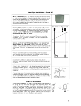
2.Device layout
Fig.1:ArcQube 324 rear view
3.Function
3.1Designated use
– wall-mounted luminaire for indoor installation
– integration into light control systems
– optical and mechanical combination of several luminaires into large illuminated screens
3.2Product features
– Different light colours, colour sequences and colour changes
– Integrated power supply
– Control by Robe media server qube control computer
– Assembly with rail system
For technical reasons in conjunction with the LED production process, brightness and colour tolerances between
individual luminaires cannot be excluded.
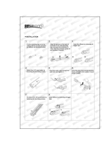
4.Fitting and electrical connection
DANGER!
Electric shock in case of accidental contact with live parts.
Electric shocks can be fatal.
Before working on the device, cut out the mains supply and cover up
live parts in the surroundings.
4.1 Fitting the device
The luminaire can be fitted alone or in a group of luminaires.The luminaire must be fitted on even surfaces.
Uneven walls must be levelled out.The fitting rails can be arranged horizontally or vertically (Fig. 2).
1.Diffuser
2.Vertical ne adjustment
3.Clear covering
4.Upper fastening rail
5.Vents
6,7 Mains connection 230V
8.Grounding connection
9.Data connection(4x RJ45)
10.Lower fastenning rail

2
3
Fig.2: Horizontal and vertical mounting rails-overview
Observe the fitting dimensions (Figs. 4 ...7).Ensure sufficient cooling. Do not cover up the vents in the device
(5) and in the mounting rail.
Make the necessary adjustments and cable connections before tting the LED module (Data and power dis-
tribution)
1.Shorten the mounting rails to the required length.
Fig.3:Shortening the mounting rail
2.Install the mounting rails.
Fig.4:Horizontal mounting rails-dimensions
Fig.5:Horizontal mounting rail-drill pattern

4
5
Fig.6:Vertical mounting rails-dimensions
Fig.7:Vertical mounting rails-drill pattern
4.Hang the luminaire with the fastening rails (4,10) on the mounting rails. If the elements are installed in a group
of luminaires, pay attention to wall spacing and venting (Fig. 12,13).Make vertical ne adjustments if necessary.
Start from bottom to the top.
Fig.9:Vertical fine adjustment
Fig.8:Suspension and wall-spacing adjustment.
5.Protect the luminaire against leaving the mounting rail.
Fig.10:Horizontal mounting rail-unhinge protection Fig.11:Vertical mounting rail-unhinge protection
6. Make the necessary electrical connections (device connection).
7.Install the side edge covering strips leaving at least a 5 mm-wide ventilation opening all around the
luminaire(s).

4
5
Fig.12:Horizontal mounting rails -ventilation
Fig.13:Vertical mounting rails -ventilation
Fig.14:Edge covering strips
4.2 Connecting the device
Do not overload the 230 V supply and the connecting leads. Do not connect more than 8 ArcQube 324 lumi-
naires to a one supply line.
Use only the 230 V connecting leads supplied with the luminaire. Replace defective leads only by the original
leads of the manufacturer.
For connection to the mains supply use ArcQube 324 power cord (Accessories) and connect to the mains in
compliance with the corresponding regulations.
CAUTION
Risk of damage to the supply leads.
Do not route the lines through the venting openings in the fastening rails.
Edge covering
strips
Edge covering
strips

6
7
Ensure equipotential bonding between ArcQube luminaire and mounting rail. Use the grounding connection
(8).
Connect the mains supply.
Connect the data control line. Use the data connecting cable supplied with the device or a straight RJ45
patch cable.
Fig.15:Power and data connection
5.Air ventilation
Space for air circulation is given by the height of vertical mounted rails. Do not cover the gap below and above
the LED wall.
6.Dimensions (mm)
Fig.16:Dimensions of the ArcQube 324
Fig.17:Dimensions of the mounting rail

6
7
Fig.18:Dimensions of the edge covering strip
7.Technical specications
Electrical
Integrated Power supply
Rated voltage : AC 110…240 V@ 50/60Hz
Power consumption: 220W max.
Power factor: approx. 0.95
Leakage current: <=360uA
Number of devices per circuit breaker C16: 8
Construction
Dimensions: 800 x 800 x 130 mm (with diffusor: 800 x 800 x 152 mm)
Robust metal framing
Inammability: B1
Type of protection:IP20
Safety class: I
Weight
ArcQube 324: 16 kg
Mounting rail (2.4m):4kg
ArcQube 324+mounting rail (1.6m): approx.17.5 kg per LED module
Thermal
Ambient temperature: +5 °C … +40 °C
Storage temperature -25 °C … +70 °C
Pixel
18 x 18 = 324 RGB – high efciency LEDs (506,25 px/m²)
Internal Resolution: 14 Bit
SBAM Modulation
Temperature compensated LED drivers
Optical
Clear covering (PETG with a transmission rate of 90%)
Snap-on diffuser (PETG with a transmission rate of 80%)
Beam angle without diffusor: approx. 120°, with diffusor: approx. 170°
Controlling
Input source: VGA at max. 60 frames/s
One control Unit (Media Server QubeControl) grabs the input signal and distributes to all panels in
the system
Preview window in the Media Fusion QubeControl Software
Very low latency (input-output: max. 50 ms)
Realtime parameters
Brightness 1-100% (255 steps. Exponential curve)
Intensity red 1-100% (255 steps. Exponential curve)
Intensity green 1-100% (255 steps. Exponential curve)
Intensity blue 1-100% (255 steps. Exponential curve)
Gamma 1.0 – 3.0 in steps of 0.1
Release time 0 – 1.000 ms in steps of 4 ms
LED frame rate 600 – 1.100 frames/s in steps of 2 frames/s
Scaling factor of the grabbed videostream
Frame size and position
Size and form of the ArcQube 324 array

8
9
Startup procedure,wiring and controlling
Intuitive,graphical and fast startup without any manual addressing
Denition of non-rectangular arrays
Distribution of video data over 1GBase-T-Ethernet (cat 5e,6 or 7 cable)
Automatic brightness detection and optimization for maximum brightness of the array
Daisy chain of power cable for up to 8 ArcQubes 324
Integrated Ethernet switch with 4 Ethernet ports
8.Included items
ArcQube 324 incl.diffusor 80% transmission (No. 10070052)....................1pc
ArcQube 324 power connecting cable (No. 10070060)..............................1pc
ArcQube 324 data connecting cable (No. 10070061).................................1pc
Set Adjustment [4xscrew] (No.18060110)...................................................1 pc
Set Look-Plate [2x plate+4x screw] (No.18060111)....................................1 pc
9.Optional accessories
Mounting rail 2.4m long.......No. 17050159
Edge covering strip .............No .10980051
10.Maintenance access, replacement,cleaning
No maintenance is necessary for the LED modules. Replacement of one LED Module can be done easy by
dismounting one raw from the top to the bottom. Exchange the complete LED-module by disconnecting data
and power cable. Connect and mount the new one.
Regular cleaning of the clear covering (diffuser)will ensure the maximum light output,A soft lint-free cloth mois-
tened with any good glass cleaning uid is recommended, under no circumstances should alcohol or solvents
be used!
Specications are subject to change without notice.

8
9
/