Bradley ABP-1WCA Installation guide
- Category
- Sanitary ware
- Type
- Installation guide

P.O. Box 309, Menomonee Falls, WI USA 53052-0309
800 BRADLEY (800 272 3539) +1 262 251 6000
bradleycorp.com
Installation
215-1813 Rev. C; ECN 16-03-002
© 2016 Bradley
Page 1 of 4 1/11/2016
ABP-1WCA Surface Mount
Ablution System
Air Metering Valve AST
TouchTime™ (TT)
Single Valve(SV & SVL)
WARNING
Make sure that all water supply lines have been flushed and then completely turned off before beginning
installation. Debris in supply lines can cause valves to malfunction.
IMPORTANT
Read this entire installation manual to ensure proper installation. When finished with the installation, file
this manual with the owner or maintenance department. Compliance and conformity to local codes and
ordinances is the responsibility of the installer.
Separate parts from packaging and make sure all parts are accounted for before discarding packaging
material. If any parts are missing, do not begin installation until you obtain the missing parts.
Product warranties may be found under “Products” on our web site at www.bradleycorp.com.
Table of Contents
Pre-Installation Information ..........................2
Rough-Ins .......................................3
Installation .......................................4
Cleaning and Maintenance ..........................4

2
1WCA Surface Mount Ablution System Installation
1/11/2016 Bradley • 215-1813 Rev. C; ECN 16-03-002
Pre-Installation Information
WARNING! This ablution system may not protect the user from scalding if other temperature controlling
devices in the plumbing system should fail.
Material
The ablution panel is constructed of stainless steel.
Supply Inlets
Supply inlets are 3/8" O.D. Comp (without supply stop) or 5/8" O.D. comp (with optional supply stop) flexible hose and
are accessible by removing the panel from the wall.
Supplies Required
• Water supply piping to connect 3/8" O.D. Comp (without supply stop) or 5/8" O.D. comp
(with optional supply stop) flexible hoses
• 1/2"-20 wall anchors to mount ablution panel to wall
• 110/210 VAC power source for 24 VAC Class II transformer (for TouchTime
™
models only)
• 24 VAC Class II transformer, available from Bradley (for TouchTime
™
models only)
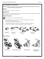
Valve Options
TouchTime (TT) Air Metering VAlve (AST) Single Valve (SV) Single Valve Lever
Handle (SVL)
See service guides for part/troubleshooting information.
PRPK Transformer
269-645 4RT
PPK ABL Transformer
US (TYPE A)
S83-134 1RT
PPK ABL Transformer
EU (TYPE F)
918-304 1RT
PPK ABL Transformer
UK (TYPE G)
918-303 1RT

3
Installation 1WCA Surface Mount Ablution System
Bradley • 215-1813 Rev. C; ECN 16-03-002 1/11/2016
Rough-in (as viewed from front)
1
A
Rough-in the wall opening and
supply piping as required for
your installation.
Flush supply lines before making connections.
Type Height
Ablution with seat 29" (740mm)
Ablution without seat 37" (940mm)
Ablution with Lavatory 59" (1499mm)
Recommended Ablution System Height
(Finished floor to spout/head)
Supply inlets are 3/8" O.D. Comp (without
supply stop) or 5/8" O.D. comp (with optional
supply stop) flexible hose and are accessible by
removing the ablution panel from the wall.
Refer to the product dimensions and images for
suggested tempered supply line rough-in location.
8" X 8" (203 X 203mm) opening required
6-1/4"
(159mm)
6-1/4"
(159mm)
5"
(127mm)
5"
(127mm)
5-1/2"
(137mm)
10-3/4"
(273mm)
10-3/4"
(273mm)
5-3/8"
(137mm)
2-1/4"
(55mm)
Spout/Head
(SPSS type water exit)
Spout/Head
(SPSS type water exit)
Spout/Head
(SX type water exit)
Spout/Head
(SX type water exit)
Supply
(recommended location)
2" (51mm)
6-1/2"
(166mm)
6-1/2"
(166mm)
2-1/2"
(64mm)
3-5/8"
(92mm)
1-7/8"
(48mm)
7-1/4"
(184mm)
7-1/4"
(184mm)
TT & AST Valves
SV & SVL Valves
2"
(48mm)
6-1/4"
(157mm)
6-1/4"
(157mm)
3-1/2"
(89mm)
Supply
(recommended location

4
1WCA Surface Mount Ablution System Installation
1/11/2016 Bradley • 215-1813 Rev. C; ECN 16-03-002
Cleaning and maintenance instructions for stainless steel
Material Description: Stainless steel is extremely durable, and maintenance is simple and inexpensive. Proper care,
particularly under corrosive conditions, is essential. Always start with the simplest solution and work your way toward
the more complicated.
Routine cleaning: Daily or as often as needed use a solution of warm water and soap, detergent, or ammonia.
Apply the cleaning solution per the manufacturer’s instructions and always use a soft cloth or sponge to avoid
damaging the finish.
Stubborn Stains: To remove stains from stainless steel use a stainless steel cleaner and polish such as Ball
®
stainless steel cleaner or a soft abrasive. Always follow the manufacturer’s instructions and apply in the same
direction as the polish lines.
CAUTION! Never use ordinary steel wool or steel brushes on stainless steel. Always use stainless steel
wool or stainless steel brushes.
Special Situations for Material
Fingerprints and Smears: To remove fingerprints or smears use a high quality stainless steel cleaner and polish in
accordance with the manufacturer’s instructions. Many of these products leave a protective coating that helps prevent
future smears and fingerprints.
Grease and Oil : To remove grease and oil use a quality commercial detergent or caustic cleaner. Apply in
accordance to the manufacturer’s instructions and in the direction of the polish lines.
Precautions: Avoid prolonged contact with chlorides (bleaches, salts), bromides (sanitizing agents), thiocyanates
(pesticides, photography chemicals, and some foods), and iodides on stainless steel equipment, especially if acid
conditions exist.
CAUTION! Do not permit salty solutions to evaporate and dry on stainless steel.
The appearance of rust streaks on stainless steel leads to the belief that the stainless steel is rusting. Look for the
actual source of the rust in some iron or steel particles which may be touching, but not actually a part of the stainless
steel structure.
NOTE: Strongly acidic or caustic cleaners may attack the steel, causing a reddish film to appear. The use of these
cleaners should be avoided.
Brand Names: Use of brand names is intended only to indicate a type of cleaner. This does not constitute an
endorsement, nor does the omission of any brand name cleaner imply its inadequacy. Many products named are
regional in distribution, and can be found in local supermarkets, department and hardware stores, or through your
cleaning service. It is emphasized that all products should be used in strict accordance with package instructions.
Install Ablution Panel
2
A
Position the ablution panel flush and level on
the wall, then mark the screw hole locations.
B
Install the (4) wall anchors (supplied by
installer) for 1/4"-20 hex socket screws in
the screw hole locations.
C
Connect the 3/8" O.D. comp (without supply
stop) or 5/8" O.D. comp (with optional supply
stop) hose/stop to supply piping.
Flush supply lines before making connections.
Supplies are brought in through
the wall in back of the unit.
D
If installing a 1F ablution panel with
TouchTime, refer to installation sheet
215-925 for electrical connections.
E
Turn stops to the open position, turn on
water supply, then inspect the system to
make sure there are no leaks.
F
Mount the panel to the wall using the
1/4"-20 x 3/4" hex socket screws supplied.
-
 1
1
-
 2
2
-
 3
3
-
 4
4


Bradley ABP-1WCA Installation guide
- Category
- Sanitary ware
- Type
- Installation guide
Ask a question and I''ll find the answer in the document
Finding information in a document is now easier with AI
Related papers
-
Bradley TouchTime S83-360 Operation And Service Manual
-
-
-
-
-
Bradley WF2708 Installation guide
-
-
-
-
Other documents
-
 Pfister G134-3444 Operating instructions
-
Sterling SVL-B User manual
-
IRWIN 10506629 Datasheet
-
-
 Gunnar Optiks PPK-03001Z Datasheet
-
IBM Switch 15 User manual
-
 Gunnar Optiks PPK-00701 Datasheet
-
-
 Agromehanika AGS 2000 EN Instructions For Use Manual
-
 Qeedji SLATE106 User manual


