Eaton Crouse-hinds series User manual
- Category
- Carbon monoxide (CO) detectors
- Type
- User manual
This manual is also suitable for
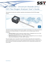
Eaton Crouse-Hinds series analyzers are designed to provide precise and reliable measurement of oxygen levels in various applications. Their key capabilities include:
-
Accurate Oxygen Measurement: These analyzers utilize advanced sensing technology to deliver accurate and consistent oxygen concentration readings across a широкий range of gases and environments.
-
Versatile Range and Sensitivity: With auto-ranging capabilities, the Eaton Crouse-Hinds series analyzers can measure oxygen levels from 0.01 ppm to 100%, making them suitable for diverse applications, from trace oxygen detection to high-concentration monitoring.


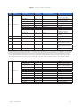
-
 1
1
-
 2
2
-
 3
3
-
 4
4
-
 5
5
-
 6
6
-
 7
7
-
 8
8
-
 9
9
-
 10
10
-
 11
11
-
 12
12
-
 13
13
-
 14
14
-
 15
15
-
 16
16
-
 17
17
-
 18
18
-
 19
19
-
 20
20
-
 21
21
-
 22
22
-
 23
23
-
 24
24


Eaton Crouse-hinds series User manual
- Category
- Carbon monoxide (CO) detectors
- Type
- User manual
- This manual is also suitable for
Eaton Crouse-Hinds series analyzers are designed to provide precise and reliable measurement of oxygen levels in various applications. Their key capabilities include:
-
Accurate Oxygen Measurement: These analyzers utilize advanced sensing technology to deliver accurate and consistent oxygen concentration readings across a широкий range of gases and environments.
-
Versatile Range and Sensitivity: With auto-ranging capabilities, the Eaton Crouse-Hinds series analyzers can measure oxygen levels from 0.01 ppm to 100%, making them suitable for diverse applications, from trace oxygen detection to high-concentration monitoring.
Ask a question and I''ll find the answer in the document
Finding information in a document is now easier with AI
Related papers
-
Eaton Crouse Hinds Z1030 User manual
-
-
Eaton TN02 520-1001 User guide
-
-
Eaton Crouse-Hinds MTL GECMA WS 24 User manual
-
Eaton MTL K522 Operating instructions
-
-
-
Eaton TN03 520-1002 Operating instructions
-
Other documents
-
 Ionalysis OM2 Purge Monitor User manual
-
ADC MGA3000 series Operating instructions
-
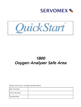 Servomex xendos 1800 Series Quick start guide
-
RADWAG MA 210.5Y.NS User manual
-
 Co2meter Oxy-Flex Oxygen Analyzer User guide
-
 Teledyne 9060 User manual
-
 Co2meter Zirconia Oxygen Sensor System Quick start guide
-
ABB 6553 Series User manual
-
Rosemount OCX 4400 O2 / Combustibles Transmitter-Rev 2.0 Owner's manual
-


