Page is loading ...

ACD-31P
ACD-41PQ
1000A Clamp-on
Power Quality Meters
Users Manual
Mode d’emploi
Bedienungshandbuch
Manuale d’Uso
Manual de uso
Användarhandbok
•
•
•
•
•

English
ACD-31P
ACD-41PQ
1000A Clamp-on
Power Quality Meters
Users Manual
ACD-31P_Rev001
© 2008 Amprobe Test Tools.
All rights reserved.

2
Limited Warranty and Limitation of Liability
Your Amprobe product will be free from defects in material and workmanship for 1
year from the date of purchase. This warranty does not cover fuses, disposable batteries
or damage from accident, neglect, misuse, alteration, contamination, or abnormal
conditions of operation or handling. Resellers are not authorized to extend any other
warranty on Amprobe’s behalf. To obtain service during the warranty period, return the
product with proof of purchase to an authorized Amprobe Test Tools Service Center or
to an Amprobe dealer or distributor. See Repair Section for details. THIS WARRANTY
IS YOUR ONLY REMEDY. ALL OTHER WARRANTIES - WHETHER EXPRESS, IMPLIED OR
STAUTORY - INCLUDING IMPLIED WARRANTIES OF FITNESS FOR A PARTICULAR PURPOSE
OR MERCHANTABILITY, ARE HEREBY DISCLAIMED. MANUFACTURER SHALL NOT BE LIABLE
FOR ANY SPECIAL, INDIRECT, INCIDENTAL OR CONSEQUENTIAL DAMAGES OR LOSSES,
ARISING FROM ANY CAUSE OR THEORY.
Since some states or countries do not allow the
exclusion or limitation of an implied warranty or of incidental or consequential damages,
this limitation of liability may not apply to you.
Repair
All test tools returned for warranty or non-warranty repair or for calibration should be
accompanied by the following: your name, company’s name, address, telephone number,
and proof of purchase. Additionally, please include a brief description of the problem or
the service requested and include the test leads with the meter. Non-warranty repair or
replacement charges should be remitted in the form of a check, a money order, credit card
with expiration date, or a purchase order made payable to Amprobe
®
Test Tools.
In-Warranty Repairs and Replacement – All Countries
Please read the warranty statement and check your battery before requesting repair.
During the warranty period any defective test tool can be returned to your Amprobe
®
Test
Tools distributor for an exchange for the same or like product. Please check the “Where to
Buy” section on www.amprobe.com for a list of distributors near you. Additionally, in the
United States and Canada In-Warranty repair and replacement units can also be sent to a
Amprobe
®
Test Tools Service Center (see address below).
Non-Warranty Repairs and Replacement – US and Canada
Non-warranty repairs in the United States and Canada should be sent to a Amprobe
®
Test
Tools Service Center. Call Amprobe
®
Test Tools or inquire at your point of purchase for
current repair and replacement rates.
In USA In Canada
Amprobe Test Tools Amprobe Test Tools
Everett, WA 98203 Mississauga, ON L4Z 1X9
Tel: 877-AMPROBE (267-7623) Tel: 905-890-7600
Non-Warranty Repairs and Replacement – Europe
European non-warranty units can be replaced by your Amprobe
®
Test Tools distributor for
a nominal charge. Please check the “Where to Buy” section on www.amprobe.com for a
list of distributors near you.
European Correspondence Address*
Amprobe
®
Test Tools Europe
In den Engematten 14
79286 Glottertal, Germany
Tel.: +49 (0) 7684 8009 - 0
*(Correspondence only – no repair or replacement available from this address. European
customers please contact your distributor.)

3
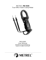
➊
Transformer Clamp Jaws
for AC current magnetic
field pick up
➋
Jaw marking lines for
ACA (& thus Power)
position error indication
➌
Hand/Finger Barrier to
indicate the limits of safe
access to the jaws during
current measurements
➍
Push-buttons for special
functions & features
➎
Input Jack for all
functions EXCEPT non-
invasive ACA current (&
thus Power) function
➏
Common (Ground
reference) Input Jack
for all functions EXCEPT
non-invasive ACA current
(& thus Power) function
➐
Slide-switch Selector to
turn the power ON/OFF
and Select a function
➑
LCD display
➒
Jaw trigger for opening
the transformer clamp
jaws
➓
Jaw center Indicators,
at where best ACA (&
thus Power) accuracy is
specified
This user’s manual uses only
representative model(s) for
illustrations. Please refer
specification details for
function availability to each
model.

4
ACD-31P / ACD-41PQ
1000A Clamp-on Power Quality Meters
CONTENTS
Symbols .............................................................................................................................................5
Safety Information ...........................................................................................................................
5
Unpacking and Contents .................................................................................................................6
Introduction ......................................................................................................................................
6
Operation .........................................................................................................................................
6
Alignment marks (see Fig. 1) .....................................................................................................
6
PEAK-rms Hold
(see figure 2) ................................................................................................7
HOLD
(Data Hold) ..................................................................................................................7
THD%-F (Total Harmonic Distortion-Fundamental) (see figure 3) ..........................................
7
SELECT / Backlight (
) .............................................................................................................7
Frequency (see figure 4) ............................................................................................................
7
Auto Power Off function ...........................................................................................................
7
RS232C PC computer interface capabilities ...............................................................................8
AutoVA
TM
Measurement (see figures 5) ...................................................................................8
Resistance Measurement (See Fig. 6) ........................................................................................
8
Continuity Test (See Fig. 6) ........................................................................................................
8
Temperature Measurement (see figure 7) ................................................................................8
Power Measurement ..................................................................................................................9
Power Measurement - Single Phase (Ø) (see figure 8) ...........................................................9
Power Measurement – 3 Phase (Ø) - 3 Wire (see figure 9) .....................................................
9
Power Measurement - 3 Phase (Ø) - 4 Wire (see figure 10) ..................................................
9
Power Factor (PF) ....................................................................................................................
10
Maintenance and Repair ..............................................................................................................10
Battery Replacement (see Fig. 11) ..........................................................................................
11
Specifications .................................................................................................................................11
General .....................................................................................................................................
11
Electrical (23 °C ± 5 °C) < 75% RH ...........................................................................................
12

5
SYMBOLS
Battery
Refer to the manual
Double insulated
Dangerous Voltage
Direct Current
Earth Ground
Alternating Current
Audible tone
Conforms to relevant Australian
standards.
Complies with EU directives
Do not dispose of this product
as unsorted municipal waste.
Underwriters Laboratories.
Application around and
removal from hazardous live
conductors is permitted
SAFETY INFORMATION
The ACD-31P and ACD-41PQ Digital Clamp meters conform to EN61010-1:2001;
EN61010- 2-032:2002; CAT III 600 V, class 2 and pollution deg.2
This instrument is EN61010-1 certified for Installation Category III (600V). It is
recommended for use in distribution level and fixed installations, as well as lesser
installations, and not for primary supply lines, overhead lines and cable systems.
Do not exceed the maximum overload limits per function (see specifications) nor the
limits marked on the instrument itself. Never apply more than 600 Vdc/600 V ac rms
between the test lead and earth ground.
Warnings and Precautions
Before and after hazardous voltage measurements, test the voltage function on a
known source such as line voltage to determine proper meter functioning.
Disconnect the test leads from the test points before changing meter functions.
Disconnected from the meter’s test leads before measuring current.
Inspect the Clampmeter, test leads and accessories before every use. Do not use any
damaged part.
Never ground yourself when taking measurements. Do not touch exposed circuit
elements or test probe tips.
Do not operate the instrument in an explosive atmosphere.
To reduce the risk of fire or electric shock, do not expose this product to rain or
moisture.
The meter is intended only for indoor use. To avoid electrical shock hazard, observe the
proper safety precautions when working with voltages above 60 VDC or 30 VAC rms.
These voltage levels pose a potential shock hazard to the user.
•
•
•
•
•
•
•
•
•
•
•

6
Before and after hazardous voltage measurements, test the voltage function on a
known source such as line voltage to determine proper meter functioning.
Keep your hands/fingers behind the hand/finger barriers (of the meter and the test
leads) that indicate the limits of safe access of the hand-held part during measurement.
Inspect test leads, connectors, and probes for damaged insulation or exposed metal
before using the instrument. If any defects are found, replace them immediately.
This Clamp-on meter is designed to apply around or remove from un-insulated
hazardous live conductors. Individual protective equipment must be used if hazardous
live parts of the installation could be accessible.
Exercise extreme caution when: measuring voltage >20 V // current >10 mA // AC power
line with inductive loads // AC power line during electrical storms // current, when the
fuse blows in a circuit with open circuit voltage >1000 V // servicing CRT equipment.
Remove test leads before opening the case to change the battery.
Disconnect circuit power and discharge all high-voltage capacitors before testing
resistance, continuity, diodes, or capacitance.
To avoid false readings, which could lead to possible electric shock or personal injury,
replace the batteries as soon as the low battery indicator () appears.
CAUTION
For non-invasive ACA current measurements, clamp the jaws around only one single
conductor of a circuit for load current measurement. More than 1 conductor will cause
false readings.
UNPACKING AND CONTENTS
Your shipping carton should include
1 ACD-31P or ACD-41PQ
1 Test lead set
1 Type K Thermocouple probe
2 AAA - 1.5V Batteries
1 Users Manual
1 Carrying Case
If any of the items are damaged or missing, immediately return the complete package to
the place of purchase for an exchange.
INTRODUCTION
The ACD-31P and ACD-41PQ are True RMS responding, autoranging, 400 Amp / 600 V
Clamp-On power quality meters. The features include AC / DC voltage, AC / DC current,
Resistance, Continuity and Power Quality measurements.
OPERATION
Alignment marks (see Fig. 1)
Place conductor within the jaws at the intersection of the indicated marks as close as
possible to maximize the accuracy of the reading.
•
•
•
•
•
•
•
•

7
PEAK-rms Hold (see figure 2)
Peak-rms captures and displays the maximum RMS value of surge voltage or current with
durations as short as 65ms when in Vac or Aac.
Press and hold Peak-rms button for 2 beeps to enter this mode.
The LCD annuciators ‘P-‘ & ‘Max’ are turned on.
Press and hold Peak-rms button for 2 beeps to exit this mode.
HOLD (Data Hold)
Freezes the reading present on the LCD at the moment the button is pressed.
Set up the meter for the type of measurement desired.
Connect the test leads or clamp jaws to the circuit/component to be measured.
Press Hold button.
The LCD reading will freeze and display ‘
‘. You may now remove the test leads and the
reading will not change until you press the Hold button again
Caution
Connection to a Hazardous Live circuit will still display the previous reading. This
function will not update the reading.
THD%-F (Total Harmonic Distortion-Fundamental) (see figure 3)
Fundamental distortion is the percentage ratio of the Total Harmonics RMS value to the
Fundamental RMS value of a voltage or current signal.
THD%-F = (Total Harmonics RMS / Fundamental RMS) x 100%
An ideal sinusoidal waveform has a value of 0.00 THD%. A highly distorted sinusoidal
waveform may have higher THD% value, up to several hundred.
Note: Used with Vac or Aac, THD%-F displays values up to 99 THD% in the secondary mini
display. Press THD%-F button to move THD%-F readings to main display to show readings
up to 999.9 THD%. Pressing THD%-F button will alternate the reading location.
SELECT / Backlight (
)
Press Backlight button more than 1 second, enable/disable Backlight.
Press the SELECT / Backlight button to step through the manually selected V-A Auto
function options:
Auto
→ THD% Aac → THD% Vac → Vdc → Auto
Frequency (see figure 4)
Displays the line frequency when in Vac or Aac. Trigger levels vary with the ranges.
Press the ‘Hz’ button to display the signal frequency.
Press the ‘Hz’ again to return to previous display.
Auto Power Off function
The clamp meter powers down automatically after approximately 17 minutes of inactivity.
To turn it back on, move the function selector switch to OFF and back to a measuring
function.
To disable Auto Power Off, press and hold the HOLD button while moving the slide switch
1.
2.
3.
1.
2.
3.
4.
1.
2.

8
to the desired function from OFF.
RS232C PC computer interface capabilities
The instrument is equipped with an optical isolated data output port at the back case
near the battery compartment. An optional PC interface kit RS232 KIT2 (Optical Adapter
Back, RS232 Cable and Amprobe Download Suite) is required to connect the meter to PC
computer thru RS232C protocol.
To enable the RS-232 output, press-and-hold the Hz button while sliding the function-
selector to a function.
The LCD displays ’
‘ to confirm activation after the Hz button is released.
To disable the RS-232 output, slide the function-selector to any other position.
AutoVA
TM
Measurement (see figures 5)
Select the AutoVA position.
With no input, the meter displays “Auto” when it is ready.
If no ACA current input via the jaws and a voltage signal > 2.4 Vdc or 30 Vac (40 Hz to
500 Hz) is present, the meter will display the voltage value with annunciator.
If no voltage signal is present on ‘+” COM terminals and a ACA current signal > 1 ACA
(40 Hz to 500 Hz) is present, the meter will display the current value and ~ A.
The Auto-VA feature stays at the auto-select function as long as its signal remains
above the specified threshold.
Press the SELECT button momentarily to manually step thru the functions (ACA
→ ACV
→ DCV → Auto-VA).
Resistance Measurement (See Fig. 6)
Select the ‘ Ω ‘ function .
Insert the test leads into the jacks. The red lead into V/
Ω jack, and black lead into COM
jack.
Remove power from the circuit being tested and discharge all the capacitors.
Connect the test leads to the circuit, the resistance measured will be displayed.
If OL appears on the highest range, the resistance is too large to be measured.
Continuity Test (See Fig. 6)
Select the ‘' function.
Insert the test leads into the jacks, the red lead into V/
Ω jack, and black lead into COM
jack.
Remove power from the circuit being tested and discharge all the capacitors.
Connect the test leads to the circuit,
The resistance will be displayed and the buzzer sounds when the resistance value is
between 10 and 300 Ω.
Temperature Measurement (see figure 7)
Select the °C/°F position.
Press SELECT button to toggle between °C and °F measurement functions.
Insert the banana-plug type-K temperature bead probe noting correct polarity.
1.
2.
3.
1.
2.
3.
4.
5.
6.
1.
2.
3.
4.
5.
1.
2.
3.
4.
5.
1.
2.
3.

9
Power Measurement
Polarity configuration note:
When measuring load circuits with power absorptions, positive (‘+’ implied) W or kW (Real
Power) readings indicate correct measurement setups. Negative readings (“-“ segment on)
indicate either the clamp-on jaws direction or the test leads polarity is reversed in such
cases. Correct the setups to get correct readings.
Power Measurement - Single Phase (Ø) (see figure 8)
Select the Power position.
Press SELECT button momentarily to select W (real power), VAR (reactive power) or VA
(apparent power) measurement functions.
Connect COM input to neutral or GRD.
Connect ‘ + ‘ input to the phase being tested.
Clamp jaws around the phase wire
The display will show reading, W (real power), VAR (reactive power) or VA (apparent
power) measurement and PF.
Power Measurement – 3 Phase (Ø) - 3 Wire (see figure 9)
Select the Power position.
Press SELECT button momentarily to select W (real power) or VA (apparent power)
measurement functions.
Connect COM input to Ø 3 terminal .
Connect ‘ + ‘ input to Ø 1 terminal
Clamp jaws around to Ø 1 wire
The display will show reading, W (real power) or VA (apparent power) measurement
and PF.
Write down the reading as kW1, kVA1
Connect COM input to Ø 3 terminal .
Connect ‘ + ‘ input to Ø 2 terminal
Clamp jaws around to Ø 2 wire
The display will show reading, W (real power) or VA (apparent power) measurement
and PF.
Write down the reading as kW2
Load Balanced Unbalanced
kW Total kW1 + kW2 kW1 + kW2
kVA Total 1.732 * kVA1 not applicable
kVAR Total √ kVA Total
2
- kW Total
2
not applicable
Power Measurement - 3 Phase (Ø) - 4 Wire (see figure 10)
Select the Power position.
Press SELECT button momentarily to select W (real power), VA (apparent power) or
VAR (reactive power) measurement functions.
1.
2.
3.
4.
5.
6.
1.
2.
3.
4.
5.
6.
7.
8.
9.
10.
11.
12.
1.
2.

10
Connect COM input to neutral or ground terminal.
Connect ‘ + ‘ input to Ø 1 terminal
Clamp jaws around to Ø 1 wire
The display will show reading, W (real power), VA (apparent power)or VAR (reactive
power) measurement and PF.
Write down the reading as kW1, kVA1, kVAR1
Connect COM input to neutral or ground terminal.
Connect ‘ + ‘ input to Ø 2 terminal
Clamp jaws around to Ø 2 wire
The display will show reading, W (real power), VA (apparent power) or VAR (reactive
power) measurement and PF.
Write down the reading as kW2, kVA2, kVAR2
Connect COM input to neutral or ground terminal.
Connect ‘ + ‘ input to Ø 3 terminal
Clamp jaws around to Ø 3 wire
The display will show reading, W (real power), VAR (reactive power) or VA (apparent
power) measurement and PF.
Write down the reading as kW3, kVA3, kVAR3
Load Balanced Unbalanced
kW Total 3 * kW1 kW1 + kW2 + kW3
kVA Total 3 * kVA1 kVA1 + kVA2 + kVA3
kVAR Total 3 * kVAR1 kVAR1 + kVAR2 + kVAR3
Power Factor (PF)
Total Power Factor =
Real Power (V rms * A rms * Cos θ )/Apparent Power (V rms * A rms)
“A-lags” annunciator indicates an inductive circuit, or Current A lags Voltage V (phase-
shift angle θ is “+”).
“A-lags” not visible indicates a capacitive circuit, or Current A leads Voltage V (phase-shift
angle θ is “-”).
MAINTENANCE AND REPAIR
If there appears to be a malfunction during the operation of the meter, the following
steps should be performed in order to isolate the cause of the problem:
Check the battery.
Review the operating instructions for possible mistakes in operating procedure.
Inspect and test the test leads for a broken or intermittent connection.
Except for the replacement of the battery or test probes, repair of the multimeter
should be performed only by a Factory Authorized Service Center or by other qualified
instrument service personnel. The front panel and case can be cleaned with a mild solution
of detergent and water. Apply sparingly with a soft cloth and allow to dry completely
before using. Do not use aromatic hydrocarbons or chlorinated solvents for cleaning.
3.
4.
5.
6.
7.
8.
9.
10.
11.
12.
13.
14.
15.
16.
17.
1.
2.
3.

11
Battery Replacement (see Fig. 11)
Warning
To prevent electrical shock or meter damage, disconnect the meter’s test leads from any
circuit and the meter, then turn the meter off before removing the battery cover. Battery
replacement should be performed in a clean environment and with appropriate care taken
to avoid contaminating the meter’s interior components.
Remove the screws and lift the battery cover.
Replace the batteries with the same type (1.5V AAA). Note polarity guide below the
battery.
Replace the battery cover and screws.
SPECIFICATIONS
General
Display :
Voltage functions: 6000 counts LCD display(s)
Power, Ohm & Hz functions: 9999 counts LCD display(s)
ACA clamp-on function: 4000 counts LCD display(s)
Update Rate :
Power function: 1 per second nominal
Voltage, ACA clamp-on, Ohm, Hz & Temperature functions: 4 per second nominal
Polarity : Automatic
Operating Temperature :
0°C to 40°C; < 80% RH @ < 31°C; decreasing linearly to 50% RH
@ 40°C
Altitude : Indoor operation, below 2000m.
Storage Temperature : -20°C to 60°C, < 80% R.H. (with battery removed)
Temperature Coefficient :
nominal 0.15 x (specified accuracy)/ °C @ (0°C -18°C or 28°C
-40°C)
Sensing : True RMS sensing
Power Supply : standard 1.5V AAA Size (NE DA 24A or IE C LR03) battery X 2
Low Battery :
Below approx. 2.4V
Power Consumption :
Voltage, ACA, Hz & Power functions: 10mA typical
Ohm & Temperature functions: 4mA typical
APO Timing : Idle for 17 minutes
APO Consumption :
10µA typical
Jaw opening & Conductor diameter : 45mm max
Dimension : 224 x 78mm x 40mm (8.9 x 3.1 x 1.6 in.)
Weight : 224 gm approx
Safety LVD: Meets EN60101-1:2001; EN61010-2-032(2002), Category III- 600 Volts ac & dc;
pollution degree : 2
1.
2.
3.

12
EMC: EN 61326-1 This product complies with requirements of the following
European Community Directives: 89/336/EEC (Electromagnetic Compatibility) and
73/23/EEC (Low Voltage) as amended by 93/68/EEC (CE Marking). However, electrical
noise or intense electromagnetic fields in the vicinity of the equipment may disturb the
measurement circuit. Measuring instruments will also respond to unwanted signals that
may be present within the measurement circuit. Users should exercise care and take
appropriate precautions to avoid misleading results when making measurements in the
presence of electronic interference.
Electrical (23 °C ± 5 °C) < 75% RH
AC Voltage
Voltage Range Accuracy
600.0V
50Hz to 60Hz
± (0.5% rdg + 5d)
45 to 50Hz, 60 to 500Hz
± (1.5% rdg + 5d)
500Hz to 3.1kHz
± (2.5% rdg + 5d)
CMRR : > 60 dB @ DC to 60 Hz, Rs = 1 k
Ω
Input Impedance: 2 M
Ω, 30 pF nominal
Crest Factor: < 2.3 : 1 at full scale; < 4.6 : 1 at half scale
ACV AutoVA
TM
Threshold: 30VAC (40 to 500 Hz) nominal
DC Voltage
Range: 600.0 V
Accuracy: ± (0.5% rdg + 5d)
NMRR : > 50 dB @ 50/60 Hz
CMRR : >120 dB @ DC, 50/60 Hz, Rs = 1 k
Ω
Input Impedance: 2 M
Ω, 30 pF nominal
DCV AutoVA
TM
Threshold: 2.4VDC nominal
PEAK-rms HOLD (ACA & ACV only)
Response: 65ms to 90% rdg
Ohms
Range: 000.0 to 999.9
Ω
Accuracy: ± (1.0% rdg + 6d)
Open Circuit Voltage : 0.4VDC typical
Audible Continuity Tester
Audible threshold: between 10Ω and 300Ω.
Response time: 250µs
ACA Current (Clamp-on)

13
Range Frequency Accuracy
1) 2)
40.00A, 400.0A, 1000A 50 Hz / 60 Hz ± (0.5% rdg + 5d)
40.00A, 400.0A
45 to 50 Hz, 60 to 500 Hz
± (2.0% rdg + 5d)
1000A ± (2.5% rdg + 5d)
40.00A, 400.0A
500 Hz to 3.1 kHz
± (2.5% rdg + 5d)
1000A ± (3.0% rdg + 5d)
ACA AutoVA
TM
Threshold: 1A AC (40Hz ~ 500Hz only) nominal
Crest Factor:
40.00A & 400.0A: < 2.5 : 1 at full scale; < 5.0 : 1 at half scale
1000A: < 1.4 : 1 at full scale; < 2.8 : 1 at half scale
1)
Induced error from adjacent current-carrying conductor: < 0.06A/A
2)
Specified accuracy is from 1% rdg to 100% rdg of range and for measurements made at
the jaw center. When the conductor is not positioned at the jaw center, position errors
introduced are:
Add + 1% rdg to specified accuracy for measurements made WITHIN jaw marking lines
(away from jaw opening)
Add + 4% rdg to specified accuracy for measurements made BEYOND jaw marking lines
(toward jaws opening)
Temperature
Range Accuracy
-50°C to -20°C ± (2.0% rdg + 6°C)
-20°C to 300°C ± (2.0% rdg + 3°C)
-58°F to -4°F ± (2.0% rdg + 12°F)
-4°F to 572°F ± (2.0% rdg + 6°F)
Type-K thermocouple range & accuracy not included
Frequency
Range 5.00 Hz to 500.0 Hz
Accuracy: ± (0.5% rdg +4d
Range Sensitivity (Sine RMS)
40A > 4A
400A > 40A
1000A > 400A
600V > 30V
THD% rdg-F
1)
(ACD-41PQ only)

14
Range: 0.0% to 999.9%
2)
Harmonic Accuracy
3)
Fundamental ± (1.5% rdg + 6d)
2nd ~ 3rd ± (5.0% rdg + 6d)
4th ~ 16th ± (2.5% rdg + 6d)
17th ~ 46th ± (3.0% rdg + 6d)
47th ~ 51st ± (4.5% rdg + 6d)
1)
THD-F is defined as: (Total Harmonic RMS / Fundamental RMS) x 100%
2)
Range for Dual Display mode: 0% to 99%
3)
Specified accuracy @ ACA fundamental > 5A ; ACV fundamental > 50V
Total Power Factor (PF)
Range Accuracy
1)
0.10 to 0.99
F to 21st harmonic
22nd to 51st harmonic
± 3d ± 5d
1)
Specified accuracy @ ACA fundamental > 2A ; ACV fundamental > 50V
Power (VA)
Range Accuracy
1) 2)
0 to 600.0 kVA F to 10th 11th to 46th 47th to 51st
@ PF = 0.99 to 0.1
± (2.0% rdg + 6d) ± (3.5% rdg + 6d) ± (5.5% rdg + 6d)
Power (kW and kVAR)
Range Accuracy
1) 3)
0 to 600.0 kW
/ kVAR
F to 10th
11th to 25th 26th to 46th 47th to 51st
@ PF = 0.99 to
0.70
± (2.0% rdg + 6d
± (3.5% rdg
+ 6d)
± (4.5% rdg
+ 6d)
± (10% rdg +6d)
@ PF = 0.70 to
0.50
± (3.0% rdg + 6d)
@ PF = 0.50 to
0.30
± (4.5% rdg + 6d)
@ PF = 0.30 to
0.20
± (10% rdg + 6d) ± (15% rdg +6d)
1)
Specified accuracy is for ACA clamp measurement at the center of jaws. When the
conductor is not positioned at the jaw center, position errors introduced are: Add 1%
rdg to specified accuracy for ACA measurements made WITHIN jaw marking lines (away

15
from jaw opening)
Accuracy is not specified for ACA measurement made BEYOND jaw marking lines (toward
jaws opening)
2)
Add 1% rdg to specified accuracy @ ACA fundamental < 5A or ACV fundamental < 90V.
Accuracy is not specified @ ACA fundamental < 1A or ACV fundamental < 30V
3)
Add 1% rdg to specified accuracy @ ACA fundamental < 5A or ACV fundamental < 90V.
Accuracy is not specified @ ACA fundamental < 2A or ACV fundamental < 50V

17
Figure 5. VDC VAC ACA
Figure 6.
Resistance Continuity
Figure 7. Temperature

18
Φ1
Φ2
Φ3
Φ1
Φ2
Φ3
Figure 9. 3 Phase 3 Wire
kW kVA kVAR
Figure 8. Power
Φ1
Φ2
Φ3
N
Φ1
Φ2
Φ3
N
Φ1
Φ2
Φ3
N

19
Figure 11 Battery Replacement
Φ1
Φ2
Φ3
N
Φ1
Φ2
Φ3
N
Φ1
Φ2
Φ3
N
Figure 10 3 Phase 4 Wire

Please Recycle
Visit www.Amprobe.com for
Catalog
Application notes
Product specifications
User manuals
•
•
•
•
/