Page is loading ...

TE-1500
Constant
Temperature
Bath
Instruction
& Operation
Manual


i
CANNON
®
TE-1500 Thermoelectric Constant Temperature Bath
Revision 1.1b—January, 2007; CANNON
®
Instrument Company
2139 High Tech Road • State College, PA 16803 • USA
CONTENTS
1
TE-1500 OVERVIEW 1
Introduction ........................................................................................................................ 1
Bath components ................................................................................................................ 2
Safety features .................................................................................................................... 3
Operator safety ................................................................................................................... 3
TE-1500 specifications ....................................................................................................... 5
2
UNPACKING & ASSEMBLY 7
Unpacking........................................................................................................................... 7
Physical placement ............................................................................................................. 7
Assembly ............................................................................................................................ 8
Pneumatic connections ........................................................................................... 8
Electrical connections............................................................................................. 8
Platform/pump assembly .................................................................................................. 10
Selecting a bath liquid ...................................................................................................... 11
Filling the bath.................................................................................................................. 12
Mains power connection................................................................................................... 13
Draining the bath .............................................................................................................. 13
Inserting viscometer tubes/thermometers......................................................................... 14
3
BATH OPERATION 15
Setting the temperature..................................................................................................... 15
Temperature control options................................................................................. 16
Adjusting trimpots ............................................................................................................ 18
Customizing Temperatures ................................................................................... 19
4
MAINTENANCE 21
Preventative (scheduled) maintenance ............................................................................. 21
Cleaning the painted surfaces and front panel...................................................... 21
Cleaning the fans and heat sinks .......................................................................... 21
Cleaning the bath window .................................................................................... 22
Cleaning the inside of the bath vessel .................................................................. 22

ii
CANNON
®
TE-1500 Thermoelectric Constant Temperature Bath
Revision 1.1b—January, 2007; CANNON
®
Instrument Company
2139 High Tech Road • State College, PA 16803 • USA
5
TROUBLESHOOTING 23
6
USER-SERVICEABLE PARTS LIST 25
7
WARRANTY/RETURN INFORMATION 27
Products limited warranty................................................................................................. 27
Reagent and chemical warranty........................................................................................ 27
Returning a product to CANNON
®
.................................................................................. 28
A
APPENDIX A—THERMOMETRY 29
Kinematic viscosity and temperature ............................................................................... 29
ASTM thermometer tables ............................................................................................... 30
ASTM D 445 — checking the ice point........................................................................... 32
NBS monograph 150: ....................................................................................................... 33
Joining Separated Mercury Columns ............................................................................... 33

CANNON
®
TE-1500 Thermoelectric Constant Temperature Bath
Revision 1.1b—January, 2007; CANNON
®
Instrument Company
2139 High Tech Road • State College, PA 16803 • USA
1
CHAPTER
1
TE-1500 OVERVIEW
Introduction
Manual
This manual provides information regarding:
Functions and operations of the TE-1500 Constant Temperature Bath
Maintenance and repair of the TE-1500
Applications
The TE-1500 is designed to be used for precise kinematic viscosity
measurements between the temperatures of +10°C and -30°C. Because
of its temperature stability and ease of use, it is also suitable for use in
other applications where temperatures must be maintained within close
tolerances.
Cooling capability
The CANNON
®
TE-1500 Constant Temperature Bath is a
thermoelectrically-cooled temperature bath which can maintain tempera-
tures as low as -30°C. The TE-1500 uses air-cooled dual-stage thermo-
electric units to maintain constant low temperatures.
Precision
The precision of kinematic viscosity measurements possible with the TE-
1500 system meets the sensitivity requirements of ASTM D 445.
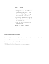
Figure 1: The
CANNON
®
TE-1500 Thermoelectric
Low Temperature Bath

2
CANNON
®
TE-1500 Thermoelectric Constant Temperature Bath
Revision 1.1b—January, 2007; CANNON
®
Instrument Company
2139 High Tech Road • State College, PA 16803 • USA
Equipment
The TE-1500 is a complete system, consisting of:
TE-1500 Constant Temperature Bath
(Control Chassis & Bath Vessel Housing)
Assorted hoses, tubes, and connecting cables
Temperature selection
A selector dial on the front panel of the TE-1500 Control Chassis permits
convenient temperature selection at 10, 0, -5, -10, -15, -20, -25, and
-30°C for kinematic viscosity measurement. After the dial has been set,
the bath will equilibrate at or near the desired temperature. The operator
can fine-tune the temperature control to within 0.01°C of the desired
temperature using either the FIXED control knob (which permits preci-
sion control at the common temperatures listed on the Temperature Select
dial) or the VARIABLE control knob (which allows for a wider range of
temperature adjustment to any setting between +10°C and -30°C).
Bath components
Control Chassis
The Control Chassis for the TE-1500 contains electrical and pneumatic
components necessary for control of bath operations. The Control
Chassis front panel provides control options, including the bath power
and heater switches, temperature selection dial, and related fine-tuning
controls for regulating bath temperature.
Bath Vessel Housing
The Bath Vessel Housing for the TE-1500 rests on top of the lower
Control Chassis. It contains a rectangular aluminum bath vessel with a
four pane, custom-designed glass window.
The Bath Vessel Housing also contains the thermoelectric modules,
finned heat sinks, fans, and fluorescent lamps with ballasts. The rear
panel has two power connectors from the lower Control Chassis, two air
pump connectors from the Control Chassis, and the bath fluid Overflow
Jar along with integral pump and tubing connections for the TE-1500
bath fluid circulation system.
Power cables
Two large diameter power cables (AC and DC) with circular connectors
on their ends are provided to take power from the lower Control Chassis
up to the upper Bath Vessel Housing. Connectors have been designed to
attach only in the proper configuration.
Air hoses
Two small diameter silicone air hoses (tube assemblies) with twist/lock
pneumatic connectors on their ends are provided to supply and return
recirculated bath vapors between the upper Bath Vessel and the Control
Chassis. Connectors have been designed to attach only in the proper
configuration.
Overflow jar
One glass jar with lid is provided to catch the bath overflow liquid. This jar
is to be placed on the rear jar support and joined to the bath fluid control
system with the provided segments of small diameter silicone tubing. Fluid
from the jar may be recirculated to the TE-1500 bath vessel by depressing
the button marked PUSH TO FILL on the rear panel of the instrument.

3
CANNON
®
TE-1500 Thermoelectric Constant Temperature Bath
Revision 1.1b—November, 1998; CANNON
®
Instrument Company
2139 High Tech Road • State College, PA 16803 • USA
Temperature probe
One thermistor sensor assembly is provided. The cable from the tempera-
ture probe is to be plugged into the back of the lower Control Chassis.
Miscellaneous accessories
Two hole covers, one 1/4-20 cap nut, and one mercury thermometer
holder are provided.
Bath apertures
The top cover of the Bath Unit contains two round holes 51 mm (two
inches) in diameter for insertion of viscometer holders. One additional
hole is provided for a thermometer.
Solid-state control circuitry
A solid-state control circuit provides proportional control of temperature.
The sensing element for the control circuit is a stainless steel-encased
thermistor.
Safety features
The following safety features are incorporated into the TE-1500 design:
Overtemp thermostat
If the temperature of the bath exceeds the operating limit (+38°C), an
internal thermostat senses the over-temperature fault condition. If such a
condition occurs, the green lamp above the on/off power will extinguish.
All power will be removed from the heater and cooling system until the
internal temperature decreases sufficiently. To reset the thermostat, verify
that the bath liquid temperature is below +38°C, turn off power to the
bath for 20 seconds and then restore power.
Probe disconnect detection
If the temperature probe is disconnected, all power to the bath heater and
bath coolers will be cut off.
Overflow drain
If the liquid level in the bath is too high, excess bath liquid will flow into
a glass jar located on the bath’s overflow platform.
Operator safety
All technicians who use the TE-1500 should follow these basic safety
procedures:
Do not place the TE-1500 system on an unstable cart or stand. The
TE-1500 should be placed on a stable laboratory table or bench.
Keep the TE-1500 away from tubs, sinks, or other water vessels. If
any liquids are spilled into the electronic components of the TE-
1500, remove power from the unit and contact CANNON
®
Instru-
ment Company before resuming TE-1500 operations.
Make sure that the TE-1500 is plugged into a grounded outlet.
Do not position power cords so that they are likely to be walked on
or pinched by items placed on or against them. Keep all connections
as neat as possible.
If the TE-1500 will not be used for an extended period of time,
unplug the power cord from the wall outlet. To disconnect the power
cord, pull it out by the plug. Never pull the cord itself.

4
CANNON
®
TE-1500 Thermoelectric Constant Temperature Bath
Revision 1.1b—January, 2007; CANNON
®
Instrument Company
2139 High Tech Road • State College, PA 16803 • USA
Do not attempt to service to TE-1500 system by removing panels and
trying to effect repairs. Contact CANNON
®
Instrument Company for
all service and repair needs.
Use a bath fluid appropriate for the desired test temperature and
operational environment. Use all proper safety precautions when
handling the bath fluid in use (refer to the Material Safety Data Sheet
included with the bath fluid for more detail).
In addition to the warnings listed above, additional cautions are posted
throughout the manual. These warnings may be designated by an appro-
priate symbol inside an equilateral triangle. General cautions are indi-
cated with an exclamation point (see diagram, left). Read and follow
these important instructions. Failure to observe these instructions can
result in permanent damage to the unit, significant property damage,
personal injury or death.
The Protective Conductor Terminal symbol is used to indicate required
ground connections for your instrument electrical supply.
WARNING
When supplying power to this instrument, connect the protective ground
(earth) terminals of the instrument to the protective conductor of the
(supplied) line (MAINS) power cord. The main plug for the power cord
should only be inserted in a socket outlet (receptacle) provided with a
protective ground (earth) contact.
Do not use an extension cord (power
cable) without a protective conductor (grounding).
The ~MAINS symbol indicates instructions or connections for the AC
power supply. The AC Power input must match the electrical specifica-
tions listed on the label on the rear panel of the instrument. The supplied
AC Mains power cord must be attached to the connector labelled
~MAINS. This connection serves as a means of disconnect and should be
readily accessible.
The (O) symbol indicates the OFF position for the electrical switches for
your unit (AC Mains or accessories).
Do not use this equipment in a manner not specified by the manufacturer.
If you do, the protection provided by the equipment may be impaired,
and you may void the manufacturer warranty.
Protective Conductor
AC Power Input Symbol
Supply OFF Symbol
( O )
General Caution

5
CANNON
®
TE-1500 Thermoelectric Constant Temperature Bath
Revision 1.1b—November, 1998; CANNON
®
Instrument Company
2139 High Tech Road • State College, PA 16803 • USA
snoitacificepS0051-ET
:eziShtaB hgihmm026×peedmm024×ediwmm573
)sehcni4.42×5.61×8.41(
:yticapaChtaB )lag66.0(sretil5.2
htaBlanretnI
:snoisnemiD
hgihmm503×peedmm38×ediwmm121
)sehcni21×52.3×57.4(
:aerAgniweiV )sehcni57.3×54.01(ediwmm59×hgihmm562
:egnaRerutarepmeT C°03-otC°01+
:noisicerP C°10.0±
gnitarepO
:snoitidnoC
,gnisnednoc-nonHR%09ot%01,C°03otC°51+
2eergednoitulloP;IIyrogetacnoitallatsnI
:thgieWhtaB )sbl59(gk1.34
gnippihShtaB
:thgieW
)sbl031(gk95
ecnailpmoC ;)CEE/32/37(evitceridegatlovwoL;)CEE/633/98(evitceridCME
).ces06,CDV0091(TOP-IH
:lacirtcelE ]rewoptinugniylppuserofebsnoitacificepstinuotegatlovenilhctam[
26A-6279#eugolatac sttaw0041,zH06/05,%01±CAstlov511,0051-ET
66A-6279#eugolatac sttaw0041,zH06/05,%01±CAstlov032,F0051-ET
:sesuF "4/1x"4/1-1,A21V052M,0051-ET
"4/1x"4/1-1,A6V052M,F0051-ET
TE-1500 specifications

CANNON
®
TE-1500 Thermoelectric Constant Temperature Bath
Revision 1.1b—January, 2007; CANNON
®
Instrument Company
2139 High Tech Road • State College, PA 16803 • USA
6
This page intentionally left blank.

CANNON
®
TE-1500 Thermoelectric Constant Temperature Bath
Revision 1.1b—January, 2007; CANNON
®
Instrument Company
2139 High Tech Road • State College, PA 16803 • USA
7
CHAPTER
2
UNPACKING & ASSEMBLY
The TE-1500 system is ordinarily shipped in 2 boxes. Please check the
packing list to make sure that all items have been received. The bath unit
housing is shipped completely assembled with the exception of the
Overflow Jar, tubing, and connecting cables.
NOTE
Retain all packing materials until the TE-1500 is connected and function-
ing properly. If any component must be returned to CANNON
®
Instru-
ment Company, it should be packed in its original shipping container.
Unpacking
CAUTION
Some TE-1500 components are quite heavy. To avoid injury, obtain
necessary assistance when lifting and moving shipping cartons and
heavier unpacked components.
Remove all components from their shipping cartons.
Remove any and all packing materials included to prevent shipping
damage (styrofoam, etc.) from the components.
Inspect all components for damage. Report any damage to the
shipper and to CANNON
®
Instrument Company immediately.
Damaged items
Retain all packing materials until the instrument is connected and func-
tioning properly. If any component(s) must be returned to
CANNON
®
Instrument Company, the damaged item(s) should be pack-
aged in the original shipping container. Refer to the final chapter of this
manual for instructions on returning defective equipment. Customers
outside the United States should contact the local CANNON
®
agent for
procedures on returning products to CANNON
®
.
Before beginning assembly, please verify that all components listed on
the packing slip are present.
Physical placement
The TE-1500 should be located on a stable, nonflammable laboratory
bench or tabletop in a position permitting convenient access to the front
and rear of the unit. The bath requires adequate ventilation for the
integral cooling fans, so a space of at least eight inches should be pro-
vided between the rear and both sides of the TE-1500 and any wall or
other obstruction. A clearance area on the right side of the unit is neces-
sary to allow access to the rear pump switch. An electrical service
MAINS power outlet matching the electrical specifications on the label
on the TE-1500 rear panel must be located within nine feet of the unit.

8
CANNON
®
TE-1500 Thermoelectric Constant Temperature Bath
Revision 1.1b—January, 2007; CANNON
®
Instrument Company
2139 High Tech Road • State College, PA 16803 • USA
Assembly
1. Position the Control Chassis in its desired location for operation.
2. Place the Bath Vessel Housing on top of the Control Chassis. The
rear mounted alignment bolt on the top rear of the Control Chassis
must mate with the hole in the alignment bracket on the bottom rear
of the upper Bath Vessel Housing.
3. Secure the connection with the supplied cap nut. The cap nut should
only be finger-tightened (see Figure 2).
4. Position the Overflow Jar on the rear platform. If the jar platform has
not yet been installed, follow the platform installation instructions in
the following section of this manual.
5. Slide the tubing from the Control Chassis reciprocating pump onto
the connector on the bottom of the Overflow Jar. Ensure that the
connection is secure.
6. Place the drain tube from the bath into the Overflow Jar through the
circular opening in the cap of the Overflow Jar.
Pneumatic connections
The pneumatic connections on the TE-1500 provide the bath agitation
and subsequent stirring by recirculating the bath vapors. To complete
pneumatic connections, locate the two silicone tube assemblies. These
assemblies have quick-connect bayonet style connectors on their ends.
Attach one of the tube assemblies to the AIR OUT connection on the
Control Chassis. Attach the other end of the assembly to its mating
connection on the Bath Vessel Housing (see Figure 3, next page).
Attach the other assembly to the AIR IN connection on the Control
Chassis. Attach the other end of the assembly to its mating connec-
tion on the Bath Vessel Housing. To secure the connections, insert the
bayonet connector from each hose into its mating connection and
turn clockwise 1/8 turn to lock.
Electrical connections
The electrical connections on the TE-1500 provide power to the instru-
ment and transfer bath power (AC and DC) from the Control Chassis to
operational components built into the Bath Vessel Housing (see Figure
3). Sensor information from the temperature probe is transferred to the
Control Chassis via the TEMP PROBE connection.
Figure 2: Securing the Bath
Vessel Housing to the
Control Chassis

9
CANNON
®
TE-1500 Thermoelectric Constant Temperature Bath
Revision 1.1b—November, 1998; CANNON
®
Instrument Company
2139 High Tech Road • State College, PA 16803 • USA
Figure 3: TE-1500 Control Chassis rear panel with Bath Vessel AC and
DC power connections highlighted
DC/AC power
Two 12"-long electrical cables deliver DC and AC bath power from the
Control Chassis up to the Bath Vessel Housing. Both of these cables have
circular plastic connectors on their ends.
Attach both of these cables to their matching connectors on the
Control Chassis and Bath Housing. Ensure a good connection by
turning the locking ring on every plug until a slight “click” is felt.
The cable with three large rectangular pins carries DC bath power to
the Bath Vessel Housing from the Control Chassis. The cable with
nine smaller circular pins carries AC bath power from the Control
Chassis to the Bath Vessel Housing.
Probe connection
Connect the small cable with the metal LEMO
®
connector to the
TEMP PROBE connection on the Control Chassis by aligning the
red dot on the LEMO
®
connector with the matching dot on the
connection and pushing the connector in until a small "click" is felt.
This connection is keyed and operates as a bayonet with a simple
push in (no twisting). To remove the connector, pull out on the
knurled section. This cable carries the temperature probe signal from
the upper Bath Vessel Housing to the Control Chassis.
PUMP connection
Using its attached plastic connector, connect the small wire cable
from the liquid pump to the PUMP connection on the lower Control
Chassis. This connection is keyed and it operates as a bayonet with a
simple push in (no twisting). The keyway must be facing upward or
insertion will not be permitted. When this connector is properly
inserted, a small “click” can be felt. Removal is accomplished with a
simple pull. This cable provides power to the Reciprocating Pump.
Mains power connection
Before connecting the instrument to your mains power source, add
bath fluid per manual instructions. See page 13 for more information
on the mains connection.

10
CANNON
®
TE-1500 Thermoelectric Constant Temperature Bath
Revision 1.1b—January, 2007; CANNON
®
Instrument Company
2139 High Tech Road • State College, PA 16803 • USA
Platform/pump assembly
The platform and pump assembly may be completed with the following
items provided by CANNON
®
Overflow Platform
Assembly screws (2)
Reciprocating Pump
Pre-cut tubing (approx. 12", 8" & 4" lengths)
1. If the rear platform is not yet attached to the Bath Vessel Housing,
attach it using the two 6-32 screws provided. The tabs which will
hold the Overflow Jar in place should be facing upward.
2. After the platform is securely in place, attach the 12" tubing to the
bath intake at the top rear of the Bath Vessel Housing by pushing the
tubing firmly over the intake nozzle. Then attach the other end of the
tube to the hose connection on top of the Reciprocating Pump (next
to the electric wire) in the same fashion.
3. Insert the other end of the reciprocating pump into the small hole on
the Overflow Platform so that the pump rests on the platform.
4. Attach one end of the
8" tube to the bottom
connection on the
Reciprocating Pump.
5. Attach the 4" tube to
the Bath Vessel
Housing overflow
outlet located above
the Overflow Plat-
form. Place the
Overflow Jar on the
platform, inserting
the other end of the
4" tube through the
lid of the jar.
6. Attach the other end of the 8" tube to the connector on the underside
of the Overflow Jar. Make sure that all connections are secure.
7. Ensure that the cable from the liquid pump is secured to the PUMP
connection on the lower Control Chassis (see instructions, page 7).
Figure 4: Overflow jar with platform and
pump installed

11
CANNON
®
TE-1500 Thermoelectric Constant Temperature Bath
Revision 1.1b—November, 1998; CANNON
®
Instrument Company
2139 High Tech Road • State College, PA 16803 • USA
Selecting a bath liquid
The “Ideal” Bath Liquid
The “ideal” bath liquid would have a low viscosity, high heat capacity,
and low vapor pressure over a wide range of temperatures. This liquid
would also have a very high flash point and be relatively inexpensive. If
the liquid were to be used in kinematic viscosity measurements where
visual observation is important, it would be clear and colorless.
Unfortunately, there is no one “ideal” liquid to use when a wide tempera-
ture range is needed. No single liquid meets all of the above require-
ments.
Temperature Ranges
The kind of liquid used in the TE-1500 Temperature Bath depends upon
the desired temperature range of the instrument. The table below lists
several different operating ranges and the liquids suitable for use in those
ranges:
SDIUQILHTAB0051-ET
ERUTAREPMET
EGNAR
HTABELBATIUS
SDIUQIL
C°01+otC°03-lohoclAlyhteM
C°01+otC°01-lohoclAlyporposI
lohoclAlyhtE
C°01+otC°5+sliOytiso
csiVwoL,retaW
CAUTION
Methyl alcohol (methanol) is very close to the “ideal” liquid; it can be
used at all temperatures in the TE-1500 operating range. However,
methanol may not be suitable for some laboratories because of its low
flash point and degree of toxicity.
Isopropyl alcohol is less toxic than methyl alcohol and somewhat less
volatile. However, it becomes very viscous at low temperatures, making
it difficult to maintain good temperature control.
CAUTION
Silicone fluids CANNOT be used in the TE-1500 Constant Temperature
Bath. NEVER place a silicone liquid in the TE-1500.
CAUTION
Do not attempt to use water as a bath fluid for operation at temperatures
of 2°C or lower.

12
CANNON
®
TE-1500 Thermoelectric Constant Temperature Bath
Revision 1.1b—January, 2007; CANNON
®
Instrument Company
2139 High Tech Road • State College, PA 16803 • USA
Bath Liquid Guidelines
When selecting a liquid for use in the TE-1500, keep the following
guidelines in mind:
YTISOCSIV
etaredomtahtoserutarepmetgnitarepohtabtawolyrevebdluohsytisocsiV
.htabehtnistneidargerutarepm
etetanimileylevitceffenacgnirrits
TAEH
YTICAPAC
retaW.yticapactaehhgihahtiwdiparsselerahtabehtnisegnahcerutarepmeT
rofseciohcrehtotsoM.sdiulfcinagrotsomfoyticapactaehehteciwttuobasah
tpmettaTONoD(.retawfoyticapactaehehtfoflahtuobaevahlliwsd
iulfhtab
).rewolroC°2foserutarepmettanoitareporofdiulfhtabasaretawesuot
YTILITALOV
.tnemhsinelpertneuqerferiuqerlliwelitalovylevitalersihcihwdiuqilA
,tceffegniloocasecudorpecafrushtabehttanoitaropavedipar,eromrehtruF
.tluciffideromlortnocerutarepmetgnikam
Filling the bath
Select a bath liquid appropriate for the intended operating temperature(s)
for the TE-1500 (see above).
Initially fill the reservoir with the bath liquid until the liquid level reaches
the overflow hole (see Figure 5) drilled into the wall of the bath.
NOTE
When operating at control temperature, the liquid level in the bath should
be about 20 mm (approx. 3/4" below the bath cover). Liquid must cover
the top edge of the baffle.
As the bath cools down to the
operating temperature, add
more bath fluid if necessary
to maintain the bath level. If
there is bath liquid in the
Overflow Jar, depress the
circular push button on the
upper left corner of the Control
Chassis. This button activates
the Reciprocating Pump
which returns liquid from the
Overflow Jar to the bath.
WARNING
Do not purposely overfill the TE-1500 bath, anticipating the contraction of
the bath liquid when it cools. The addition of more bath liquid should
occur ONLY when test temperature has been reached, and ONLY if the
liquid level is too low. Initially overfilling the bath will compromise the
overflow system, and could result in bath liquid spilling into the TE-1500,
possibly damaging the internal components and creating a hazard.
Overflow
Avoid filling the bath more than necessary after cooling to temperatures
below -20°C. The bath liquid will expand as the temperature increases.
Excess liquid will drain off into the Overflow Jar in the rear of the bath.
Periodically check the amount of liquid in the Overflow Jar. Drain the
Overflow Jar when necessary.
Figure 5:
Bath with overflow hole highlighted

13
CANNON
®
TE-1500 Thermoelectric Constant Temperature Bath
Revision 1.1b—November, 1998; CANNON
®
Instrument Company
2139 High Tech Road • State College, PA 16803 • USA
Mains power connection
Attach the MAINS power cord to the connection on the Control Chassis.
Make certain that the instrument power switch on the Control Chassis is
in the OFF position, then plug the power cord into a wall outlet with
electrical specifications matching those on the label on the Control
Chassis rear panel.
Use only the supplied, approved appliance cord for
the TE-1500 power connection.
Draining the bath
CAUTION
Remove power from the TE-1500 before attempting to remove bath fluid.
Only remove bath fluid if the bath fluid temperature is within 10°C of
ambient.
CAUTION
Use a siphon, inserted through
one of the holes for viscom-
eters, to remove fluid from the
bath. Never attempt to open
the metal bath enclosure.
Bath fluid for the TE-1500 will
need to be replaced periodi-
cally. Depending on the grade
of alcohol being used as a bath
liquid, the frequency of re-
placement may vary greatly.
Contaminants contained in
solution with the alcohol will
remain as sediment in the bath
after the alcohol evaporates. All
sediment should be removed
when replacing bath fluid. If the bath is always maintained at a cold
temperature and the holes at the top are always covered, the rate of
evaporation of the alcohol will be reduced.
Procedure
The bath liquid in the TE-1500 should be removed by siphoning action.
A general purpose siphon (see Figure 6) is available wherever kerosene
heaters are sold. This simple plastic device has an integral squeeze pump
to start the siphoning with a long, straight input hose and a flexible
output hose.
An alternate method is a vacuum system with a container trap for con-
tainment of the bath fluid. The continuous vacuum in such a system
provides an easy means to remove any solid dirt particles and completely
empty the bath.
Using a siphon or vacuum hose placed into one of the two instrument
holes at the top, transfer all of the bath liquid into another container
(Metal waste receivers, if used, should be grounded). Briefly turn on bath
power and energize the Reciprocating Pump by depressing the circular
Figure 6: Removing fluid to a
grounded metal waste receiver with
a siphon

CANNON
®
TE-1500 Thermoelectric Constant Temperature Bath
Revision 1.1b—January, 2007; CANNON
®
Instrument Company
2139 High Tech Road • State College, PA 16803 • USA
14
push button on the upper left corner of the Control Chassis rear panel.
This will empty any remaining fluid from the Overflow Jar and connec-
tion hoses into the bath. Turn off the TE-1500 after the remaining fluid
has been returned to the bath vessel.
CAUTION
Do NOT leave TE-1500 power on without liquid in the bath!
Siphon or vacuum the remaining bath liquid from the bath vessel.
Inserting viscometer tubes/thermometers
The top cover of the TE-1500 contains two round holes 51 mm (two
inches) in diameter for the insertion of viscometer tube holders. An
additional hole is provided for the insertion of a thermometer.
Viscometer tube insertion
Remove the cover(s) from the top of the bath and carefully place the
viscometer tube(s) into the plastic holders in the top cover. Insert the
tube(s) slowly to permit adequate time for the bath liquid displaced by
the tubes to drain through the overflow hole into the Overflow Jar.
Monitor the liquid level in the Overflow Jar carefully. If necessary, empty
excess fluid from the jar.
Thermometer immersion
Proper thermometer immersion is critical for viscosity measurements.
Even a calibrated thermometer will read incorrectly if is it improperly
immersed in the bath. “Total immersion” kinematic viscosity thermom-
eters should be used with the bulb and entire mercury column beneath the
surface of the liquid, but with the emergent stem above the surface at
ambient temperatures.
Kinematic viscosity thermometers are available from CANNON
®
Instrument Company. Consult APPENDIX A (Thermometry) for addi-
tional details.
NOTE
Different thermometers have different installation requirements. Refer to
the information included with the thermometer in use for specific installa-
tion instructions.

CANNON
®
TE-1500 Thermoelectric Constant Temperature Bath
Revision 1.1b—January, 2007; CANNON
®
Instrument Company
2139 High Tech Road • State College, PA 16803 • USA
15
CHAPTER
3
BATH OPERATION
Setting the temperature
Front Panel Description
The controls for the TE-1500 are divided into 4 different “control areas”,
as shown on the front panel (see Figure 7). In this manual, the four
control areas will be abbreviated as follows:
Front Panel Control Areas
CONTROL AREA ABBREVIATION
POWER P
TEMPERATURE T
TEMPERATURE ADJUST TA
HEAT H
Figure 7: TE-1500 front panel
Start-up Procedure
1. Verify that the TE-1500 has been assembled and installed correctly.
2. Turn the bath POWER switch on. The green lamp above the POWER
switch should illuminate, indicating the thermostat is functioning. The
green lamp in the switch indicates active “mains” power.

16
CANNON
®
TE-1500 Thermoelectric Constant Temperature Bath
Revision 1.1b—January, 2007; CANNON
®
Instrument Company
2139 High Tech Road • State College, PA 16803 • USA
CAUTION
Do not operate the TE-1500 with an inadequate volume of liquid in the
bath vessel.
3. Turn on the LIGHTS switch on the front panel and verify that the
lamps illuminating the interior of the bath are on.
Temperature control options
There are two ways to set the TE-1500 Bath temperature, preset or
custom temperature selection. Both procedures are described in the
following sections. If the desired bath temperature corresponds to a value
on the Temperature Select switch, use the Pre-Set Temperature Selec-
tion procedure. If the temperature is not one of the Temperature Select
switch values, use the Custom Temperature Selection procedure.
Note that dials and switches are identified with their control area abbre-
viations. For example, TA - FIXED refers to the left-hand dial (marked
FIXED) in the TEMPERATURE ADJUST section of the control panel.
NOTE
Both Temperature Adjust dials on the
TE-1500 are equipped with dial locks
(see Figure 8) to prevent accidental
changing of dial settings. Push the
lock upward to release the lock and
move the dial. When the dial has
been set to the proper position, push
down on the lock to relock the dial.
Before beginning the temperature
selection procedures, release the dial
locks on the TA-FIXED and TA-
VARIABLE dials and set the dials to
their midpoints (500). Then relock the
dials.
Pre-Set Temperature Selection
Selection procedure
1. Turn the T - SELECT dial to the appropriate temperature.
NOTE
The green LED on the right side of the front panel will glow while the
cooling units are operating. This light does not mean that the bath is at
the proper operating temperature. Do NOT use this lamp to gauge the
temperature of the bath. Always use the thermometer in the bath to
confirm bath temperature.
2. Move the TA-SELECT switch to the left (FIXED) position.
3. If the desired temperature is warmer than the present bath tempera-
ture, turn on the H - HEAT switch . When the switch is turned on,
the HEAT LED on the front panel will glow continuously until the
desired temperature is reached. To achieve temperature stability more
quickly, turn the H - HEAT switch off approximately 2-3°C before
your temperature probe indicates the desired temperature.
Figure 8:
Dial lock on TA-VARIABLE dial
/