Page is loading ...

Anemometer
USER
MANUAL
Product number: 6410
for Vantage Pro2™ and
EnviroMonitor®
Davis Instruments, 3465 Diablo Avenue, Hayward, CA 94545-2778 U.S.A. • 510-732-9229 • www.davisinstruments.com
R


1
Welcome to
Anemometer
(6410)
The anemometer measures and displays wind speed and direction. The data is used
to calculate other wind-related information such as wind run, wind chill, and the
temperature-humidity-sun-wind index. This anemometer can be used with
EnviroMonitor or any Vantage Pro2-compatible system. Installed in a Sensor
Transmitter, it can be used to include additonal wind stations in your existing
system when reporting to a WeatherLink Live.
Contents of Package
The package contains the following:
• Anemometer arm with 40 feet (12.2 meters) of cable
• Wind vane
• Wind cups
• Anemometer base
Wind Cups
Anemometer
Base
Anemometer Arm
with 40 feet (12.2 meters)
of cable
Wind Vane

2
Hardware Kit
Tools for Setup
• Cable Clips or Weather-Resistant Cable Ties
Note: Make sure the clips or ties you use to secure the anemometer cable have screw holes or other
means for mounting the cable. Do not use metal staples to secure the cables.
• Small Screwdrivers
• Adjustable Wrench
• Hand-Held Compass or Local Area Map
Assemble the Anemometer
Attach the Wind Vane
The wind direction has been calibrated in the factory so that the wind direction
will be correct when the arm is installed pointing north and the vane is installed
correctly.
1. Slide the wind vane onto the wind vane shaft. The shaft’s cross section is D-
shaped to ensure that the anemometer is installed correctly.
2. Tighten the set screw in the wind vane with the Allen wrench.
1/4" Flat Washers
1/4" Lock Washers
1/4" Hex Nuts
U-Bolt
.05" Allen
Wrench
1/4" x 3" Lag Screws
#4 x 1-1/8"
Machine Screw
#4 Tooth
Lock Washer
#4-40 Hex Nut

3
Attach the Wind Cups
1. Push the wind cups up onto the anemometer’s stainless steel wind cup shaft.
2. Slide the wind cups up the shaft as far as possible.
3. Use the Allen wrench provided to tighten the set screw on the side of the wind
cups.
4. The wind cups should drop slightly when you let go.
5. Ensure that the set screw is screwed in fully and very tight. Failure to do so
will cause the anemometer to function improperly.
6. Spin the wind cups.
7. If the wind cups spin freely, the anemometer is ready for installation.
If the wind cups don’t spin freely, take them off and repeat the wind cup
installation process.
Tighten set
screw with
Allen wrench
Push cups onto
stainless steel
shaft
Wind cup shaft

4
Attach the Anemometer Arm to the Base
1. Insert the anemometer arm into the base, sliding the cable through the notch in
the base as shown in illustration.
2. Be sure to line up the small hole in the arm with the holes in the base.
3. Insert the machine screw through the holes in the base and arm.
4. Slide the tooth-lock washer and hex nut onto the machine screw. Tighten the
hex nut while holding the screw with a Phillips head screwdriver to prevent it
from turning.
5. Press the sensor cable firmly and completely into the zig-zagging channel in
the base, starting from the arm and progressing downward to the bottom of the
base.
Insert
anemometer arm
into base
Slide cable
through notch
#4 Tooth
Lock Washer
Hex Nut
#4 x 1-1/8”
Machine Screw
IMPORTANT:
Make sure cable
is secure in channel

5
Installing the Anemometer
Orient the Wind Vane
The wind vane rotates 360° to display current and dominant wind directions on the
compass rose of the console display. To obtain accurate readings, the vane must be
correctly oriented when mounting the anemometer outside. By default, the wind
vane reports the correct wind direction if the anemometer arm points true north.
To ensure correct orientation of the wind vane, mount the anemometer so that the
arm points true north.
If your anemometer arm cannot be mounted aiming true north, you will need to
calibrate the wind direction, either on your console for Vantage Pro2 or on your
WeatherLink.com page for EnviroMonitor. See your Vantage Pro2 Console
Manual or Envoy Manual.
Anemometer Siting Guidelines
• Mount the anemometer so that the arm is aimed true north.
Note: If your anemometer cannot be mounted aiming true north, you will need to calibrate the wind
direction on your console to display accurate wind directions. See your console user manual
• For best results, place the anemometer at least 7' (2.1 m) above surrounding
obstructions such as trees or buildings that obstruct wind flow.
• If mounting on a roof, mount the anemometer at least 7' (2.1 m) above the roof
apex (when using a Mounting Tripod, install the anemometer at the very top of
the pole).
• If mounting the ISS and the anemometer together, such as on a pole or a
wooden post, mount the anemometer so it is at least 12'' (0.3 m) above the top
of the rain collector cone for best results.
• The standard for meteorological and aviation applications is to place the
anemometer 33' (10 m) above the ground. Seek professional help for this type
of installation.
• The standard for agricultural applications is to place the anemometer 6' (2 m)
above the ground. This is important for evapotranspiration (ET) calculations.
Note: For roof mounting, and ease of installation, we recommend using the optional mounting tripod
(#7716). For other installations, use the Mounting Pole Kit (#7717).
Note: For more detailed siting suggestions, see Application Note #30: Reporting Quality Observations to
NOAA on the Davis Support web site (http://www.davisnet.com/support/weather).

6
Installing the Base on a Wooden Post or Surface
1. Use a drill with a 3/16" (5-mm) drill bit to make pilot holes in these locations.
2. Drive the 3" lag screws through the flat washers and the holes in the
anemometer base and into the wood.
Installing the Anemometer on a Pole or Pipe
• Use the Mounting Tripod (#7716) for easy roof-mounting.
• Use the Mounting Pole Kit (#7717) to raise the installation height by up to
37.5" (0.95 m).
• With the supplied U-bolts, the anemometer can be mounted on a pole having
an outside diameter ranging from 1
1
/
4
" to 1
3
/
4
" (32 – 44mm).
• Larger U-bolts (not supplied) can be used to mount to a pole with a maximum
outside diameter of 2
1
/
2
" (64mm).

7
• To mount on a smaller pole, obtain a U-bolt that fits the base openings but that
has a shorter threaded section.
1. Place the U-bolt around the pole so that its two ends extend through the holes
in the mounting base. Loosely secure with the flat washers, lock washers and
hex nuts.
2. Raise the anemometer to the desired height on the pole and swivel it so the
anemometer arm is pointing north.
3. Using an adjustable wrench or 7/16" wrench, tighten the hex nuts until the
anemometer is firmly fastened on the pole.
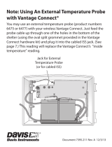
Securing the Cable
To prevent fraying or cutting the anemometer cable
where it is exposed to weather, secure it so it doesn’t
whip about in the wind. Use cable clips or weather
resistant cable ties to secure the cable. Place clips or
ties approximately every 3 to 5 feet (1 to 1.6 m).
Note: Do not use metal staples to secure cables. Metal staples can cut the cables.
U-Bolt
1/4" Flat Washer
1/4" Lock Washer
1/4" Hex Nut
Anemometer
Mounting Base
Securing cable

8
Optional: Anemometer Cable Length
Considerations
• Your anemometer includes a 40' (12
m) cable. This can be extended up to
540' (165 m) using optional extension
cables purchased from Davis
Instruments.
• If most of the anemometer cable
length is unused, the coiled cable
length can be stowed once the
anemometer has been installed on a
site. Attaching the anemometer cable
to the mounting pole using the
supplied cable tie is the recommended
option.
• Keep the anemometer cable coiled if
possible during the anemometer
assembly so that it is easily stowed
once installation is complete.
Maintenance
Your anemometer does not require any regular maintenance.
CAUTION: DO NOT attempt to lubricate the wind cup shaft and bearings or the wind vane
shaft. Natural or synthetic lubricants will inhibit the normal operation of the
anemometer.
Anemometer
Cable
Cable Tie

9
Troubleshooting
“The wind cups are spinning but my console displays 0 mph.”
The signal from the wind cups may not be making it back to the display. Check
your cables for visible nicks and cuts. Look for corrosion in the WIND connector
on the SIM and on splices in the cable. If using an extension cable, remove it and
test using only the anemometer cable. Contact Technical Support and ask for a
wind test cable if the problem has not been resolved.
Note: If the anemometer is sending no data, the wind display indicates 0 speed and a north direction.
“The wind direction is stuck on north, or displays dashes.”
It is likely that there is a short somewhere between the wind vane and the display.
Check the cables for visible nicks and cuts. Look for corrosion in the “WIND”
jack on the SIM and on splices in the cable (if any). If possible, remove any
extensions and try it with the anemometer cable only. If none of these steps get the
wind direction working, contact Technical Support and ask for a wind test cable.
“The wind cups don’t spin or don’t spin as fast as they should.”
The anemometer may be located where wind is blocked by something, or there
may be friction interfering with the cups’ rotation. Remove the wind cups (loosen
the set screw) and clear out any bugs or debris. Turn the shaft the cups rotate on. If
it feels gritty or stiff, contact Davis Technical Support.
Note: Do not lubricate the shaft or bearings in any way. When replacing the cups, make sure they are
not rubbing against any part of the anemometer head.
“Readings aren’t what I expected them to be.”
Comparing data from your ISS to measurements from TV, radio, newspapers, or a
neighbor is NOT a valid method of verifying your readings. Readings can vary
considerably over short distances. How you site the ISS and anemometer can also
make a big difference. If you have questions, contact Technical Support.

Anemometer for Vantage Pro2 and EnviroMonitor
Product Numbers 6410
Document Number: 07395.277 Rev. C, 6/18/19
EnviroMonitor,
®
Vantage Pro
®
, Vantage Pro2
™
, WeatherLink Live
™
, Vantage Vue
®
and
Envoy
™
are trademarks of Davis Instruments Corp., Hayward, CA.
© Davis Instruments Corp. 2019 All rights reserved.
Information in this document subject to change without notice. Davis Instruments Quality
Management System is ISO 9001 certified.
3465 Diablo Avenue, Hayward, CA 94545-2778 U.S.A.
510-732-9229 • Fax: 510-732-9188
®
[email protected] • www.davisinstruments.com
Contacting Davis Technical Support
For questions about installing or operating your Anemometer,
please contact Davis Technical Support. We’ll be glad to help.
Note: Please do not return your unit for repair without prior authorization.
Specifications
Operating Temperature. . . . . . . . . . . . -40° to +149°F (-40° to +65°C)
Wind Direction
Display Resolution . . . . . . . . . . . . 16 points (22.5°) on compass rose, 1° in
numeric display
Accuracy . . . . . . . . . . . . . . . . . . . . ±3°
Wind Speed
Range . . . . . . . . . . . . . . . . . . . . . . 2 - 200 mph, 3 - 322 kph, 2 - 173 knots,
1 - 89 m/s
Accuracy . . . . . . . . . . . . . . . . . . . . ±2 mph (3 kph, 2 kts, 1 m/s) or ± 5%,
whichever is greater
Online www.davisinstrumentscom
See the Weather Support section for copies of user
manuals, product specifications, application notes, and
more.
E-mail [email protected]
Telephone (510) 732-7814
Monday - Friday, 7:00 a.m. - 5:30 p.m. Pacific Time.
/