JetStream L2 Managed Switch
04 Introduction
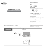
LED Indication
10/100M
Note: Only for ports1-24 of T2500-28TC.
Green On: Running at 100Mbps, but no activity.
Green Flashing: Running at 100Mbps and is transmitting or receiving data.
Yellow On: Running at 10Mbps, but no activity.
Yellow Flashing: Running at 10Mbps and is transmitting or receiving data.
Off: No device is linked to the corresponding port.
1000M
10/100/1000M
10/100/1000BASE-T
Note: 1000M for ports25-28 of T2500-28TC, 10/100/1000M for T2500G-10TS and
ports 1-48 of T2600G-52TS, 10/100/1000Base-T for ports 9T-12T of TL-SG5412F.
Green On: Running at 1000Mbps, but no activity.
Green Flashing: Running at 1000Mbps and is transmitting or receiving data.
Yellow On: Running at 10/100Mbps, but no activity.
Yellow Flashing: Running at 10/100Mbps and is transmitting or receiving data.
Off: No device is linked to the corresponding port.
1000Mbps
Note: For TL-SG5412F/T2600G-18TS/T2600G-28TS/T2600G-28TS-DC and
ports1-24 of T2600G-28SQ.
On: Running at 1000Mbps.
Off: Running at 10/100Mbps or no device is linked to the corresponding port.
Link/Act
For TL-SG5412F/T2600G-18TS/T2600G-28TS/T2600G-28TS-DC/ T2600G-52TS
and ports 1-24 of T2600G-28SQ:
On: A device is linked to the corresponding port and running properly.
Flashing: Transmitting or receiving data.
Off: No device is linked to the corresponding port.
For ports 25-28 of T2600G-28SQ:
Green On: Running at 10Gbps, but no activity.
Green Flashing: Running at 10Gbps and is transmitting or receiving data.
Yellow On: Running at 1000Mbps, but no activity.
Yellow Flashing: Running at 1000Mbps and is transmitting or receiving data.
Off: No device is linked to the corresponding port.
SFP1, SFP2
Note: Only for T2500G-10TS.
Green On: A 1000Mbps device is linked to the corresponding port, but no activity.
Green Flashing: A 1000Mbps device is linked to the corresponding port and data is
being transmitted or received.
Yellow On: A 100Mbps device is linked to the corresponding port, but no activity.
Yellow Flashing: A 100Mbps device is linked to the corresponding port and is
transmitting or receiving data.
Off: No device is linked to the corresponding port but no activity.
For T2500G-10MPS/T2600G-28MPS
T2500G-10MPS/T2600G-28MPS has an LED mode switch button which is used to switch the LED
status indication. When the Speed LED is on, the port LED is indicating the data transmission rate.
When the PoE LED is on, the port LED is indicating the power supply status. By default the Speed LED