Page is loading ...

INSTALLATION INSTRUCTIONS
FOR
DUCTED WHOLE HOUSE FANS (HUB UNITS)
Fan Models: CX1401HUB, CX1801HUB
Read all warnings and instructions before beginning to install this fan.
WARNING – TO REDUCE THE RISK OF FIRE, ELECTRIC SHOCK, OR INJURY TO
PERSONS, OBSERVE THE FOLLOWING:
a) Installation work and electrical wiring must be done by qualified person(s) in accordance with all
applicable codes and standards, including fire-rated construction.
b) Sufficient air is needed for proper combustion and exhausting of gases through the flue
(chimney) of fuel burning equipment to prevent back drafting. Follow the heating equipment
manufacturer’s guideline and safety standards such as those published by the National Fire
Protection Association (NFPA), and the American Society for Heating, Refrigeration and Air
Conditioning Engineers (ASHRAE), and the local code authorities.
c) When cutting or drilling into wall or ceiling, do not damage electrical wiring and other hidden
utilities.
d) WARNING – TO REDUCE THE RISK OF FIRE OR ELECTRIC SHOCK, DO NOT USE THIS
FAN WITH ANY SOLID-STATE SPEED CONTROL DEVICE.
e) Use this unit only in the manner intended by the manufacturer. If you have questions, contact the
manufacturer.
f) Before servicing or cleaning unit, switch power off at service panel and lock the service disconnecting
means to prevent power from being switched on accidentally. When the service disconnecting means
cannot be locked, securely fasten a prominent warning device, such as a tag, to the service panel.
CAUTION
DOUBLE CHECK FAN BLADES ARE SECURE TO HUB PRIOR TO INSTALLATION.
BLADES CAN BE DAMAGED DURING SHIPMENT AND CAN BECOME A HAZARD
UPON ACTIVATION OF MOTOR!
1. This unit has an unguarded propeller. Do not use in locations readily accessible to people or animals.
2. For general ventilating use only. Do not use to exhaust hazardous or explosive materials and vapors.
3. Carbon monoxide is an odorless, colorless gas that can kill. It may be drawn into the house by operating
this fan if your fuel-burning equipment is not properly maintained, or if you lack adequate attic space.

2
Ventamatic, Ltd. | 100 Washington Ave, Mineral Wells, TX 76068 ▪ Phone: (800) 433-1626 ▪ www.bvc.com
INSTALLATION INSTRUCTIONS
VERY IMPORTANT
Please read before attempting installation
The damper assembly box is designed for horizontal installation only—the dampers will not function in the
vertical position.
The damper assembly box is designed to fit in between 16 inch on center or 24 inch on center ceiling joists.
The damper assembly box requires a rough opening to be cut that is 14-½” x 22-½”.
CX1401- Adequate for 533 sq. ft. house. Requires a minimum of 310 sq. in. of Net Free Exhaust Area
CX1801- Adequate for 930 sq. ft. house. Requires a minimum of 535 sq. in. of Net Free Exhaust Area
*When measuring vents for NFA, remember that louvers and screens cut down considerably on the available free air — this can
be factored in by measuring the length by the width of the open vent area and dividing the resulting surface size in half.
DO NOT OVERSIZE YOUR FAN! Additional installation of exterior vents may be required to
provide sufficient Net Free Exhaust Area (NFA) for your fan to operate safely and effectively.
Remember – bigger is not always better with Whole House Fans. A smaller fan that operates
efficiently will always be preferable to a fan that is too big for its application.
Tools Needed
Materials Needed
Drill
Small drill bit (3/32" recommended)
Gloves
Eye protection
12 foot tape measure or longer
Pencil or marker
Circular saw for cutting lumber
Drill bit for driving screws
Hammer
24" long straight edge or construction level
Keyhole or saber saw
3/8" drill bit
Wrenches for hex head bolts and nuts
Phillips screwdriver
Slotted screwdriver
Needle-nose pliers
36 inch length of wire for location marking
(unfolded coat hanger works well)
2x4 or larger lumber for framing
3-1/2" wood screws or nails
2" wood or drywall screws

Ventamatic, Ltd. | 100 Washington Ave, Mineral Wells, TX 76068 ▪ Phone: (800) 433-1626 ▪ www.bvc.com
3
Parts Included
Fan, hanging bracket, duct and transition
assembly
Damper assembly box
Intake grille and mounting screws
Rafter bracket
5/16" x 2-1/2" bolt
5/16" x 3/4" bolt
2 - 5/16" locknuts
4 - 5/16" flat washers
Nylon bracket spacer
Foil tape
If you are missing any of the above parts that are supposed to be included please contact our Customer Service
department and we will assist you. (800) 433-1626
Step 1 (In the living space):
Find a spot where you would like to install the damper assembly, drill a small hole in the middle of this location
in the ceiling material and feed a wire through to mark it in the attic space above.
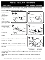
Step 2 (In the attic):
Find the wire that was fed through the ceiling below and check for wires, pipes and other obstructions around the
area where the product will be installed. If anything is in the way of the installation you may have to choose a
different location for the damper assembly to be installed.
Pull back the insulation material to allow for a well visible work space.
Insulation
Existing ceiling joist
Insulation
Blocks added in step 2
Hole from step 1
Existing ceiling joist
Corner hole from step 2 (x4)
A

4
Ventamatic, Ltd. | 100 Washington Ave, Mineral Wells, TX 76068 ▪ Phone: (800) 433-1626 ▪ www.bvc.com
IMPORTANT: Ensure that the distance between the ceiling joists members is at least 14-½ inches. Also ensure there is
an acceptable fan mounting location 10 feet or less from the location where the wire is being used to mark the location of
the damper assembly box installation.
If there are obstructions to the installation, the distance between the joists is less than the minimum of 14-½” or the closest
fan mounting location is further than 10 feet you will need to choose a different location to install the damper assembly
box.
Mark a 14-½” x 22-½” rectangle on the back side of the ceiling material. Center this rectangle around the wire
that has been used to mark the center of the hallway.
Drill a small hole in each corner of the rectangle to use as guides for cutting the ceiling material from the living
space below as shown in Figure A.
Optional, but recommended: Measure the exact length between the two ceiling joists between which you have
marked the rectangle. Cut two pieces of lumber, 2x4 or larger, to fit in between the two ceiling joists. Place these
pieces of lumber flush with the ceiling material in the attic and running in between the two ceiling joists. Fasten
these pieces of lumber to the ceiling joists using screws or nails to create a wooden “frame” around the rectangle
that you have drawn.
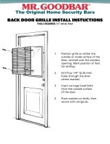
Step 3 (Living space):
In the living space below use a straight edge to mark a rectangle on the ceiling by connecting the four small holes
that were drilled at the corners in the attic previously as shown in Figure B.
Re-measure this rectangle to ensure that it measures the necessary 14-½” x 22-½”. Make any adjustments needed
to allow the damper box to fit properly.
Cut along the rectangle drawn on the ceiling using a keyhole saw or saber saw.
B
22-1/2”
14-1/2”

Ventamatic, Ltd. | 100 Washington Ave, Mineral Wells, TX 76068 ▪ Phone: (800) 433-1626 ▪ www.bvc.com
5
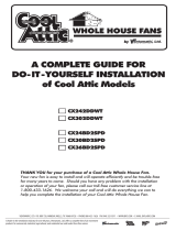
Step 4 (Living space):
Slide the damper box assembly up into the hole and secure it to the ceiling structure using a minimum of a two
inch (2”) long wood or sheetrock screws. Be sure to avoid installing these screws toward the middle of the
damper assembly flanges as the intake grille will screw in at the middle of the damper box flanges as shown in
Figure C. These screws will pass through the ceiling material and into the wooden ceiling joists or lumber in the
attic above ensuring a secure installation of the damper box.
Step 5 (Attic):
Determine to which roof rafter the fan will be mounted. The location of the fan installation will need to be less
than 10 feet away from the damper box assembly due to the length of the provided duct. The further away from
the damper box assembly the fan can be installed the quieter the apparent operation of the fan will be in the living
space below.
Using a 3/8” drill bit, drill a hole in the location chosen. This hole needs to be 1-½” up from the long, flat edge of
the rafter as shown in Figure D.
Attach the rafter bracket to the top of the fan hanging bracket using the provided 5/16” x ¾” bolt, lock nut and
washers.
Attach the rafter bracket to the rafter where the hole was drilled using the provided 5/16” x 2-½” bolt and lock nut
as shown in Figure D.
Ensure all nuts and bolts are tight on the mounting components of the fan.
If possible, manually spin the fan blade to ensure there are no obstructions that may have occurred during
shipping, handling or installation.
C
Note: Avoid placing screws in the middle when mounting the damper box. This area is used to
secure the grille in a later step.

6
Ventamatic, Ltd. | 100 Washington Ave, Mineral Wells, TX 76068 ▪ Phone: (800) 433-1626 ▪ www.bvc.com
Step 6 (Attic):
Extend the duct and duct transition down to the damper assembly box.
Fit the duct transition over the top of the damper assembly box. Ensure that it sits flush against the top of the
damper assembly box as shown in Figure E.
Use the provided foil tape to seal the seam between the duct transition and damper assembly box to prevent air
leakage when the unit is running.
D

Ventamatic, Ltd. | 100 Washington Ave, Mineral Wells, TX 76068 ▪ Phone: (800) 433-1626 ▪ www.bvc.com
7
Step 7: Hub Pairing Instructions
Apply power to the unit and observe the LED lights on the control hub. Ensure the Power LED is illuminated on
the control hub.
Download the Wi-Fan app available at your smart device store.
Navigate to the WiFi settings utility on your smart device.
Select the WVC Hub to connect. The SSID will start with WV-xxx…, which matches the ID to the label. The
label is located on the inside of the hub’s front cover.
Enter the default password to join the network. The default password is myfan.
Launch the Wi-Fan app to begin the pairing process.
For additional help: See the tutorial section in the Wi-Fan app.
Step 8 (Living space):
Test the fan by switching the unit ON. Change the speed setting using the smart app. Ensure that the damper
doors open and close when the fan is ON and OFF respectively.
Install the intake grille to the bottom side of the damper assembly from the living space below using the provided
white-headed screws.
E

8
Ventamatic, Ltd. | 100 Washington Ave, Mineral Wells, TX 76068 ▪ Phone: (800) 433-1626 ▪ www.bvc.com
Operating Instructions
Whole House Fans cool your home by pulling in fresh, cooler air from outside through open windows and doors.
For best results in a multi-story home, windows should be opened on alternate levels for most efficient cooling.
NEVER operate fan without open windows or doors.
CAUTION: If your home has a fireplace, be sure that the flue damper is closed to prevent chimney soot from being
drawn into the house by the fan. DO NOT operate the fan when a fire is burning in the fireplace.
Common Installation Issues
Motor Stops after 10-20 Minutes
Insufficient intake or exhaust Net Free Air. Open more doors and windows or increase the amount of ventilation in
the attic.
Unit is Noisy
Moving the fan further into the attic will reduce the apparent noise.
Make sure all screws and bolts are tightened.
Verify Exhaust NFA. Inadequate NFA will result in the unit working harder and making more noise.
Not Enough Airflow
Verify NFA intake and exhaust requirements are being met. Lack of airflow can be the result of lack of fresh air and
lack of ventilation to expel the air. Try channeling the air by opening only doors and windows in a certain area to
funnel the wind flow.
Fan Does Not Start on Low Speed
Verify that the fan will start on High Speed. Switch to Low Speed from the High setting. For additional
troubleshooting, please contact our customer support team.

Ventamatic, Ltd. | 100 Washington Ave, Mineral Wells, TX 76068 ▪ Phone: (800) 433-1626 ▪ www.bvc.com
9
VENTAMATIC, LTD.
LIMITED WARRANTY
Ventamatic, Ltd. extends this warranty to the original occupying owner of the home where this product is installed, that this product
will be free from defects of material or workmanship for the time period listed by model number below:
CX1401HUB, CX1801HUB Limited 10-Year
No subsequent purchaser of the home in which the product was installed will be entitled to the benefits of this warranty. Ventamatic,
Ltd. will replace the defective part or component only and return the new part to you freight prepaid. Customer must bear all other
expenses incurred, including labor required for field repair or replacement, and cost of return shipping of the defective part or
component to Ventamatic.
Customer must also bear the cost of replacement of any part or component and the shipping charges incurred for the replacement and
return of any part or component not covered by this warranty, including parts or components damaged by customer.
Ventamatic, Ltd. reserves the right to demand and receive written evidence of the date of purchase before undertaking to perform its
obligations under this warranty. YOU SHOULD, THEREFORE, RETAIN YOUR SALES SLIP FOR THE DURATION OF
THE WARRANTY, AND ATTACH IT TO ANY EVENTUAL CLAIM. In order to obtain the replacement of a part or
component, you must select one of the following methods:
A) Return to factory.
Return postage prepaid the fan or part you believe to be defective to the address below:
Ventamatic, Ltd.
100 Washington Street
Mineral Wells, TX 76067
*Include your name & address and a copy of your proof of purchase or installation.
B) Return to place of purchase.
It is suggested that you first contact the dealer to ascertain if they will honor the warranty.
There is no informal dispute settling mechanism available in the event of a controversy involving this warranty.
Any and all implied warranties shall be limited to the duration of the express warranty set forth above. In some states, limitations of
the duration of implied warranty do not apply. Ventamatic, Ltd. shall not be liable for incidental or consequential damages, whether
direct or indirect based upon breach of warranty, breach of contract, negligence or tort.
If any suit or other action is brought against Ventamatic by customer, Ventamatic and customer irrevocably waive the right to trial by
jury. Purchase and installation of this product constitutes acceptance of the terms of this warranty by customer.
/