Page is loading ...

Beamforming Microphone Array 2
Group Microphone for Professional Conferencing
Ceiling Mount installation guide

ClearOne
5225 Wiley Post Way
Suite 500
Salt Lake City, UT 84116
Telephone 1.801.975.7200
1.800.945.7730
Sales 1.800.707.6694
FAX 1.801.303.5711
E-mail [email protected]
On the Web www.clearone.com
Beamforming microphone array 2
ceiling mount installation guide
clearone document
QSG-0034-001 Rev 1.3, MARCH 2018
© 2018 ClearOne
All rights reserved. No part of this document may be reproduced
in any form or by any means without written permission from
ClearOne. Printed in the United States of America. ClearOne
reserves specific privileges.
Information in this document is subject to change without
notice.

Table of Contents
CHAPTER 1: GETTING STARTED .................................................................. 1
CONNECTIONS ..................................................................................................... 1
POWERING A BEAMFORMING MICROPHONE ARRAY 2 .........................................................1
POE CONNECTION ..................................................................................................................... 1
P-LINK CONNECTIONS ..............................................................................................................2
SKUS USED ........................................................................................................... 6
BFM2 CEILING MOUNTING KITS ...............................................................................................6
CHAPTER 2: CEILING MOUNT INSTALLATION ........................................... 7
PARTS RECEIVED ................................................................................................. 8
TOOLS REQUIRED ................................................................................................ 8
PARTS RECEIVED (CONTINUED...) ......................................................................9
PARTS NOT INCLUDED ........................................................................................ 9
LEGEND ............................................................................................................... 10
REQUIRED PARTS CHECKLIST: ..............................................................................................10
MOUNTING TO SUSPENDED CEILING .............................................................. 11
PREPARATION ..........................................................................................................................11
SUPPORT CABLE INSTALLATION ...........................................................................................12
SOLID CONCRETE CEILING STRUCTURE ...................................................................................... 12
STEEL TRUSS CEILING STRUCTURE .............................................................................................. 12
WOOD CEILING STRUCTURE .......................................................................................................... 13
TRAY INSTALLATION ................................................................................................................13
SUSPENSION COLUMN INSTALLATION .................................................................................14
MOUNT ALIGNMENT ................................................................................................................16
FLUSH MOUNT INSTALLATION .......................................................................... 17
SUSPENDED CEILING INSTALLATION ....................................................................................17
WOOD STUD INSTALLATION ...................................................................................................17
CONCRETE INSTALLATION .....................................................................................................18
BEAMFORMING MICROPHONE ARRAY 2 INSTALLATION ............................... 20
INSTALL INTERFACE BRACKET ..............................................................................................20
INSTALL AND SECURE MOUNT TO BRACKET ....................................................................... 21
ADJUSTMENTS .........................................................................................................................22
SERVICE AND SUPPORT ............................................................................. 24
TECHNICAL SUPPORT .............................................................................................................24
PRODUCT RETURNS ................................................................................................................24

Chapter 1: Getting Started 1
Chapter 1: Getting Started
Congratulations on purchasing your Beamforming Microphone Array 2 (BFM2). The BFM2 is a 2nd
generation Beamforming Microphone Array product featuring 24 microphones, and beamforming
and adaptive steering technology designed specifically for the CONVERGE® Pro 2 (CP2) products:
128, 128D, 128T, 128TD, 128V, 128VD, 120, and 48T.
» IMPORTANT: The BFM2 only can be used with CP2 systems. It is not compatible with
first generation CONVERGE Pro or Beamforming Microphone Array systems.
CONNECTIONS
This section explains the connections in BFM2 installations.
powering a Beamforming microphone array 2
Powering a BFM2 can be...
• from a CP2 via either a 200 or 650 ft. Peripheral-Link (P-Link
1
), with a single cable carrying
power, audio and control
• via a Power-Over-Ethernet (PoE) power supply/Injector
2
, third-party or ClearOne provided (a
ClearOne PoE Injector can power up to three BFM2 units)
poe connection
Use the appropriate AC cord to connect the PoE power supply to the AC power. Then plug the PoE
cable into the LAN+DC connection on the power supply. Route the PoE cable where it can be fed
through a mount assembly or to the conference table with the BFM2. Figure 1 illustrates PoE Power
Supply cable connections.
Figure 1
Power Over Ethernet (PoE) Power Supply
(Front and Back Views)
Power Cord
to AC Power
PoE Ethernet Cable to
Beamforming Microphone Array 2
» NOTE: The PoE connection is only for power, not control. If not using a ClearOne
PoE Injector or similar specification standard PoE Injector, power must be supplied
to individual units.

2 Beamforming Microphone Array 2
» NOTE: The 650 ft. cable set can only be used in a P-Link chain of up to 3 BFM2 units.
» NOTE: Cable lengths cannot be mixed in the same P-Link chain.
PoE
CP2
P-Link
(Power, Audio, Control)
200 or 650 ft.
P-Link
200 or 650 ft.
P-Link
200 or 650 ft.
Sample Scenario 1:
Connecting 3 BFM2 units to one CP2
unit with either a 200 ft., or a 650 ft. cable
set. Cable lengths cannot be mixed in the
same chain per CP2 unit.
Regular or Long Distance
power-source-selection
switch
(USB: for future use)
1
1
2
3
P-Link
Out
p-link connections
BFM2 units are connected to CP2 units and other BFM2 units via the P-Link. Each BFM2 unit has
a P-Link In and P-Link Out connection that allows units to be “chained” together with the P-Link Out
of one unit connecting to the P-Link In of the next unit, and can be chained with a set of either 200
or 650 ft. P-Link cables.
Up to three BFM2 arrays are supported per CP2 unit, as seen above in Figure 3.
Figure 3
Figure 2

Chapter 1: Getting Started 3
S. No. Feature Regular P-Link Long Distance P-Link
1 Applicable to all CP2 units YES
NO
(only supports CP2 AEC units)
2
Applicable to all peripheral units (BFM2,
DIALOG 20 Receiver, USB Expander, GPIO
Expander)
YES
NO
(only supports BFM2)
3
Same CP2 and BFM2 hardware (no hardware
changes, only software and firmware upgrades)
YES YES
4 Applicable to already sold and installed units YES YES
5 Maximum distance between units 200 feet (~60 meters) 650 feet (~200 meters)
6 Carries power, audio, control YES YES
7
Maximum number of peripheral devices in one
P-Link chain
12
(3 each: BFM2, DIALOG 20, USB Expander, GPIO
Expander)
3
(3 BFM2 only)
8 Cable specification
CAT5e/CAT6, 24 AWG, solid conductor cable.
Do not use Copper Clad Aluminum (CCA).
CAT6, 550 MHz, 23 AWG, solid conductor cable.
Do not use Copper Clad Aluminum (CCA).
9 PoE Power Injector spec
56V, Mode B, Midspan – For 3 BFM2 units
48V, Mode B, Midspan – For 1 BFM2 unit
56V, Mode B, Midspan – For 3 BFM2 units
48V, Mode B, Midspan – For 1 BFM2 unit
10 No extra cost, free to upgrade YES YES
Regular P-Link
200 ft.
PoE
DIALOG 20
Receiver
CP2
PoE
Sample Scenario 2:
Connecting 3 BFM2 units and 3 DIALOG 20 Receiver units
to one CP2 Unit via 200 ft. cables.
Figure 4
Up to 3 of each P-Link device type can be daisy-chained to a CP2 unit using a 200 ft. cable set.
» NOTE: With a standard 200 ft. P-Link cable set, only one or two P-Link connections
are required depending on where in the stack a BFM2 is placed. Only a P-Link In
cable is required if the array is at the end of a stack; both a P-Link In and P-Link Out
cable are needed if the stack continues to another array or CP2 unit.

4 Beamforming Microphone Array 2
PoE
CP2
Regular P-Link
200 ft.
P-Link
200 ft.
P-Link
200 ft.
P-Link
200 ft.
PoE
C-Link
Sample Scenario 3:
Connecting four BFM2 units in the same chain
with a two CP2 unit stack via the 200 ft cable set.
The 650 ft. cable set cannot be used in a
daisy-chain of more than 3 BFM2 units per CP2 unit.
Figure 5
Figure 6
PoE
CP2
Regular
P-Link
200 ft.
(60m)
GPIO Expander
GPIO Expander
PoE
GPIO Expander
PoE
USB Expander
USB Expander
PoE
200 ft.
(60m)
200 ft.
(60m)
200 ft.
(60m)
200 ft.
(60m)
200 ft.
(60m)
200 ft.
(60m)
200 ft.
(60m)
200 ft.
(60m)
Sample Scenario 4:
Connecting 3 BFM2 units, 3 USB expander,
3 GPIO expander, and 3 DIALOG 20 Receiver units
to a CP2 unit via 200 ft. cables. Up to 3 units of each
P-Link device type can be daisy-chained to a single CP2 unit with
200 ft. cables. Add a PoE for every 3 devices.

Chapter 1: Getting Started 5
Instructions for connecting the BFM2 are in the Beamforming Microphone Array 2 Quick-Start
Guide, and in the CONVERGE Pro 2 CONSOLE online help for configuring the BFM2.
» NOTE: Firmware upgrades and BFM2 operation are performed via the P-Link
connection. Plugging the PoE cable into the P-Link connections may cause damage
to the BFM2.
Make sure CP2 firmware is updated. Instructions for updating the firmware can be found at:
http://www.clearone.com/resources#professional_audio
Instructions for updating BFM2 firmware are included in the Beamforming Microphone Array 2
Quick-Start Guide, which is found on the ClearOne website at:
http://www.clearone.com/resources#professional_microphones
Physically, the BFM2 supports use in ceiling-mounted, wall-mounted or table-mounted modes,
giving you the option of a clutter-free conference room table area.
PoE
CP2
Long
Distance
P-Link
650 ft.
(200m)
650 ft.
(200m)
650 ft.
(200m)
C-Link
150 ft.
(45m)
Regular
P-Link
PoE
CP2
200 ft.
(60m)
200 ft.
(60m)
200 ft.
(60m)
200 ft.
(60m)
200 ft.
(60m)
200 ft.
(60m)
PoE
Sample Scenario 5:
Connecting the maximum of 3 BFM2 units to a first CP2 unit in the stack via
650 ft. cables; and 3 BFM2 units, 1 USB expander, 1 GPIO expander, and 1
DIALOG 20 Receiver unit to a second CP2 unit in the stack via 200 ft. cables.
More devices can be daisy-chained
to the 2nd CP2 unit (up to 3 of each
P-Link device type).
Figure 7

6 Beamforming Microphone Array 2
SKUS USED
The following SKUs may be used in a BFM2 installation:
Item
Part No.
White Black
BFM2 for CONVERGE Pro 2 910-3200-201 910-3200-201-B
PoE Power Supply Kit for BFM2. Contains power supply,
one AC power cable, and two 25-foot CAT5E or CAT6 RJ45
plenum cables (one used as the PoE cable and the other as
a P-Link cable). If a PoE kit is not obtained, installers will need
to provide their own PoE unit and all cables.
910-3200-202
BFM2 Ceiling Mounting Kit with 12/24/36/48” Suspension
Column
910-3200-203-
12/24/36/48
910-3200-203-
12/24/36/48-B
Gen-1 Ceiling Mounting Kit with 12/24/36/48” Suspension
Column
910-001-005-
12/24/36/48
910-001-005-
12/24-B
Wall Mounting Kit (refer to Wall Mount Installation Guide) 910-001-006 910-001-006-B
» NOTE: All mounting kits are compatible with both the BFM1 and BFM2.
Bfm2 ceiling mounting kits
What each BFM2 Ceiling Mount Kit includes:
Part No.
Kit
Includes
White Black
Mount
+
Bracket
Fixed Length
Suspension
Column
Lightweight
Suspended
Ceiling Kit
910-3200-
203
910-3200-
203-B
BFM2 Ceiling Mount Kit
without Suspension column
Yes No Yes
910-3200-
203-12
910-3200-
203-12-B
BFM2 Ceiling Mount kit with
12" Suspension Column
Yes 12" Yes
910-3200-
203-24
910-3200-
203-24-B
BFM2 Ceiling Mount kit with
24" Suspension Column
Yes 24" Yes
910-3200-
203-36
910-3200-
203-36-B
BFM2 Ceiling Mount kit with
36" Suspension Column
Yes 36" Yes
910-3200-
203-48
910-3200-
203-48-B
BFM2 Ceiling Mount kit with
48" Suspension Column
Yes 48" Yes

Chapter 2: Ceiling Mount Installation 7
Chapter 2: Ceiling Mount Installation
Once you have verified all the firmware updates and necessary connections made while executing
the tasks outlined in the Beamforming Microphone Array 2 Quick-Start Guide, you can proceed to
the physical installation of the BFM2 using one of our 2nd generation ceiling mount kits.
This section covers instructions for suspended ceiling mounting of the BFM2. For mounting to solid
ceiling or flush mounting junction box, installers will need to obtain parts independently.

8 Beamforming Microphone Array 2
#1 & #2
Phillips screwdriver
Drill bits
1/4” (6.4mm) for concrete
5/32” (4.0mm) for wood
Drill
Ruler
Pencil
Hammer
TOOLS REQUIRED
The following tools are required for suspension ceiling mount installation of the BFM2:
» IMPORTANT: ClearOne makes no claim that the information contained herein covers
all details, conditions or variations, nor does it provide for every possible contingency
in connection with the installation or use of this product.
PARTS RECEIVED
The following parts are delivered with the BFM2 Mounting Kit:
P
QTY 1
Interface Bracket
O
QTY 1
Mount
I
M3 x 8mm
QTY 4
Q
Washer for M3 Screw
QTY 4
Mount with Interface Bracket:
N
QTY 1
Suspension Column
Fixed Length Suspension Column:
For SKUs without suspension columns
and other ceiling types, the mount is also
designed to be mounted to a 1.5” NPT or
NPSM threaded suspension column, with
a minimum of 4 usable threads, following
ANSI/ASME B1.20.1 (Schedule 40, 0.154”
minimum wall thickness).
» NOTE: It requires over 1” of threads
to get 4 usable threads.
Level

Chapter 2: Ceiling Mount Installation 9
The ClearOne parts received are designed to be mounted into a suspended ceiling.
» NOTE: Your suspension column will vary by length based on the SKU purchased.
» NOTE: For SKUs without suspension columns and other ceiling types, the mount is
also designed to be mounted to a 1.5” NPT or NPSM threaded suspension column,
with a minimum of 4 usable threads, following ANSI/ASME B1.20.1 (Schedule 40,
0.154” minimum wall thickness).
Please verify that you have all the purchased parts required to complete your installation. If any
items from your order are missing or damaged, contact your ClearOne distributor immediately.
PARTS NOT INCLUDED
The following parts are required for solid ceiling or flush mount and need to be acquired independently
by installers, depending on the configuration:
10-24 x 5/8"
10-24 x 1/4"
10-24 x 1/4"
Locking Collar
5/32" (security key wrench)
Ceiling Tile Cutter
1/4" x 2" Wire Anchor
0.262" x 1-5/16" Screw Eye
Cable Lock
1/16" x 25’ Cable
Tray
1-1/2" Suspension
Column Ring
A
QTY 1
B
QTY 1
C
QTY 4
D
QTY 4
E
QTY 4
F
QTY 4
G
QTY 4
H
QTY 1
J
QTY 1
K
QTY 1
L
QTY 1
M
QTY 1
Lightweight Suspended Ceiling Kit:
PARTS RECEIVED (CONTINUED...)
Ceiling fasteners must be appropriate
to the ceiling type
» NOTE: Reference page 9 for
cutout template, if not using
Ceiling Tile Cutter (M).

10 Beamforming Microphone Array 2
LEGEND
Tighten Fastener
Loosen Fastener
Phillips Screwdriver
By Hand
Pencil Mark
Drill Hole
Security Wrench
Hammer
Ceiling Plate (Example Only)
Varies by brand and model
required parts checklist:
Mounting Type
Part
Mount +
Bracket
Suspension
Column
Suspended
Ceiling Kit
Ceiling
Fasteners
Ceiling
Plate
Suspended Ceiling Yes Yes Yes No No
Solid Ceiling or Junction Box Yes Yes No Yes Yes
» IMPORTANT: The installer is responsible to be sure the Beamforming Microphone
Array is firmly attached to sturdy support (studs, or other mounting hardware) to hold
the weight of the Beamforming Microphone Array and its mounting hardware.
Four #10 flat washers,
Four #10 x 3” Phillips head wood screws
2-1/2” to 3” suspension column

Chapter 2: Ceiling Mount Installation 11
port to center support over ceiling tile hole.
8. Tighten wing nuts.
9. Examine ceiling structure (concrete, steel
truss, or wood) above tray to identify four sup-
port cable anchor (C) locations. Each location
should be approximately 15° outboard of sup-
port holes in tray. Mark locations with pencil.
MOUNTING TO SUSPENDED CEILING
The following diagrams show how to mount the BFM2 from a suspended ceiling.
preparation
1. Determine exact location of suspension column on suspended ceiling. Mark location on lower
(finished) side of ceiling tile with pencil.
2. Remove affected ceiling tile and any adjacent tiles required for access.
9
15°
15°
x 4
x 4
x 4
5
= 1.5" (38mm)
6
7
8
x 4
Suspension
column
support
2” (51mm) Template
Figure 6
Figure 7
Figure 8
3. Press center tip of ceiling tile cutter (M) into
finished side of ceiling tile at marked loca-
tion. Cut suspension column hole through tile
using back and forth hand twisting motion.
Or use Figure 6 to the right for the cutout:
4. Reinstall ceiling tile with suspension column
hole. Ensure tile is oriented properly.
5. Install tray (A) on top of ceiling tile so that end
brackets engage primary (1.5” (38mm) high)
rails of ceiling framework.
6. Loosen four wing nuts in upper side of tray.
7. Position tray and/or suspension column sup-
10. Remove tray and ceiling tile.

12 Beamforming Microphone Array 2
support caBle installation
» IMPORTANT: Installer is responsible for making sure ceiling structure can support five
times the combined weight of all equipment. Reinforce ceiling structure as necessary
before installing cables.
solid concrete ceiling structure
» IMPORTANT: Anchors must be installed into structurally sound solid concrete with
a minimum thickness of 1.75” (44.5mm) or greater. Installation into hollow concrete
block, mortar, or concrete that exhibits cracking, spalling, or other defects may result
in failure of anchor and serious personal injury or damage to equipment!
1. Drill 1/4” diameter x 1-3/8” deep hole at each marked cable anchor support location. Ensure
hole is at least 2-1/2” from nearest concrete edge. Remove debris from hole.
2. Tap anchor (D) into each hole to a depth of at least 1” (25mm).
» IMPORTANT: Failure to properly set anchor may result in failure of anchor and serious
personal injury or damage to equipment!
3. Using claw of hammer, set anchors (D) by pulling each out approximately 1/4” (6.4mm).
4. Insert part of manufactured loop on cable (C) through hole in anchor (D). Insert end of cable
(C) through loop. Repeat for 3 remaining support locations.
1
2
3
4
1/4"
steel truss ceiling structure
1. Route end of cable (C) over truss at marked cable anchor support location and then through
cable loop. Repeat for 3 remaining support locations.
Figure 9
1
Figure 10

Chapter 2: Ceiling Mount Installation 13
wood ceiling structure
» IMPORTANT: Anchors must be installed into wood with a minimum thickness of 1.5” (38.1
mm) or greater.
1. Drill 5/32” diameter x 2” deep hole at each marked cable anchor (D) support location. Remove
debris from hole.
2. Fully thread eye lag (E) into each hole.
3. Route end of cable (C) through eye lag (E), then through cable loop. Repeat for 3 remaining
support locations.
1
5/32"
2
3
tray installation
1. Reinstall ceiling tile with suspension column hole. Ensure tile is oriented properly.
2. Reinstall tray (A) on top of ceiling tile with suspension column support centered over hole in tile.
3. Position tray (A) with four screws (G) as required:
• For 24” (610mm) Framework: Install screws through end bracket inside holes.
• For 600mm (23-5/8”) Framework: Install screws through end bracket outside holes.
3
24" (610mm)
3
600mm (23-5/8")
Figure 11
Figure 12 Figure 13

14 Beamforming Microphone Array 2
4. Thread each cable (C) completely through cable lock (F), corresponding hole in corner of tray
(A), and completely through opposite side of cable lock (F). Adjust cable tension until tray (A) is
supported entirely and evenly by all four support cables (C), but not so tight as to distort ceiling
tile framework.
» NOTE: Cable lock (F) will allow cable to enter from only one direction per side,
indicated by arrows on lock (F). Depress spring loaded pins on cable lock (F) to
release cable tension.
4
x 4
2
1
3
suspension column installation
1. Install suspension column (N) into suspension column support until tight, with a minimum of
four threads engaged.
2. Align mount (O) with end of suspension column (N).
3. Thread mount (O) up onto suspension column (N) by turning until hand tight with a minimum of
four threads engaged.
Figure 14
Figure 15

Chapter 2: Ceiling Mount Installation 15
4
(H)
(J and K)
(H)
(J)
(K)
4. Secure suspension column (N) by one of the following methods:
• Install one 10-24 x 1/4” Phillips pan head screw (H) into suspension column support, tightening
firmly against column.
• OPTIONAL: Install one 10-24 x 1/4” button head security screw (J) through locking collar (K)
into suspension column support, tightening firmly against column.
» NOTE: Locking collar (K) is designed to spin, even when screw (J) is tight.
5
(top view)
5. Install suspension column ring (B) on suspension column below ceiling tile. If necessary, bend
four tabs inward to secure ring to column.
6. Reinstall remaining ceiling tiles as required.
Figure 16
Figure 17

16 Beamforming Microphone Array 2
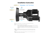
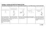
mount alignment
1. Turn mount (O) up to 1/2 turn clockwise or counter-clockwise until front of mount is facing target.
2. Secure mount to suspension column (N) by tightening set screw with a hex key wrench.
» IMPORTANT: DO NOT OVERTIGHTEN! Overtightening of set screw can damage
threads on suspension column (N).
3. Turn security screw using a Phillips screwdriver until screw cannot be seen through access hole
in mount.
2
1
3
(bottom view)
Figure 18

Chapter 2: Ceiling Mount Installation 17
1a
Ø 2.5mm
(Ø 3/32”)
45mm
(1-3/4”)
x 4
x 4
3
2
FLUSH MOUNT INSTALLATION
The following diagrams show how to flush mount the BFM2.
Figure 19
wood stud installation
1. Determine mounting location.
» IMPORTANT: Improper installation can result in serious personal injury or damage
to equipment! Structural members must be capable of supporting five times the
combined weight of all equipment being mounted.
» Note: The mount is designed to be mounted to double 2” x 4” wood stud cross
bracing (1-1/2” on center) between two ceiling joists; with a maximum drywall
covering of 5/8”.
2. Using the mount (O) as a guide, mark four mounting hole locations with a pencil. Hole locations
must be centered on 2” x 4” cross braces.
3. Drill four 3/32” (2.5mm) diameter pilot holes to a depth of 1-3/4” (45mm) deep.
suspended ceiling installation
To safely flush mount the BFM2 to ceiling tile, you must use the suspended ceiling kit.
1. Follow the instructions for mounting to suspended ceiling [see page 9, section titled MOUNTING
TO SUSPENDED CEILING]), using a 2-1/2” to 3” suspension column instead (not included;
see page 7, section titled PARTS NOT INCLUDED).
/