Page is loading ...

EN
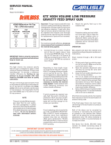
SB-4-367-K (10/2014) 1 / 4
SERVICE MANUAL
TGC-576,TLC-576 & TSC-591
HVLP LOW PRESSURE
ONE QUART CUP
Repair Kit KK-5008
IMPORTANT:
Read and follow all instructions and
SAFETY PRECAUTIONS before using this
equipment. Retain for future reference.
DESCRIPTION
These cups have a 1 quart capacity, for
pressure feed use with cup pressure
regulation. The TGC-576 aluminum cup
is designed for general applications. The
TLC-576 non-stick lined cup is suitable for
use with most common coating materials,
where small amounts of material or many
color changes are required.
The TSC-591 is a high quality, stainless
steel cup designed for use with corrosive
type materials such as waterbornes. It is
also suitable for use with finishes contain-
ing halogenated hydrocarbon solvents.
Both cups are used with KK-4980 air regu-
lator kit (order separately).
Maximim working pressure: 20 psi (1.4
bar), connecting thread 3/8" NPS.
The non-stick lined cup check valve will
prevent the cup from losing pressure.
The check valve also prevents paint from
backing up into the air tube if the cup is
tilted. The poppet stem in the cup lid al-
lows the painter to manually relieve the
cup pressure.
INSTALLATION
1. Position yoke at right angles to the gun
body with the cam (3) towards the front
of the gun.
2. Fasten lid assembly (11) to fluid con-
nector on the gun and tighten nut with
wrench.
3. Connect the air supply tube from regu-
lator to the fitting (8) on the lid.
OPERATION
Risk of injury. Cup is under pres-
sure during operation. Turn off or
disconnect air supply to spray gun
and paint cup before attaching or
removing the cup and cup lid and
before filling or cleaning. Turn the
cup regulator knob counterclock-
wise to shut off air to the paint
cup. Push down on the check valve
poppet stem (6) to relieve the cup
pressure.
Risk of injury or equipment damage.
Air pressure to the cup must never
exceed 20 psi (1.4 bar).
1. Mix, prepare and strain the material.
Remove cup (12) by moving the cam
lever counter-clockwise, fill cup. Do not
overfill.
Note
Only use a wooden or plastic paddle
or mixer for mixing material in the
non-stick lined cup (TLC-401). A
metal paddle or mixer can scratch
the non-stick lining.
2. Replace cup (12), engage pins into yoke
slots (make sure both pins are fully en-
gaged in both slots prior to tightening)
and tighten by moving cam lever (3)
clockwise. Do not lubricate cam. This
can cause it to loosen.
3. Connect air supply to gun. Make sure
gun inlet pressure and cup pressure do
not exceed maximum limits.
4. Before refilling or emptying the con-
tents of the cup, depressurize the cup
by pushing down on the check valve
poppet stem (6) to relieve pressure from
the cup. If the check valve has become
wet it is normal for a small amount of
paint mist to be discharged from stem
hole.
Note
Horizontal spraying with a full cup
could allow paint to contact the
check valve. This could affect the
operation. Check valve (10) should
be cleaned after each use.
MAINTENANCE
Lid Repair/Replacement
1. To replace a damaged part, use a 5/16
inch Allen wrench to loosen and remove
adapter (1). Nut (2), yoke and cam (3),
lid and tube assembly are now loose
for replacement.
2. Replace damaged parts on the lid and
tube assembly.
Note
To prevent leakage when reinstalling
adapter (1), apply sealant (Loctite
#262) to the first two full threads.
3. Insert threaded end of the adapter (1)
into open end of nut (2).
4. Install adapter and nut in top of lid and
tube assembly. Use a 5/16-inch Allen
wrench to tighten firmly (10-12 Ft. Lbs.).
PROP 65 WARNING
WARNING: This product contains
chemicals known to the
State of California to cause cancer
and birth defects or other
reproductive harm.
CA PROP
65

EN
SB-4-367-K (10/2014)2 / 4
Safeguards
Adequate exhaust must be provided to keep air free of
accumulations of flammable vapors
Smoking must never be allowed in the spray area.
Fire extinguishing equipment must be present in the spray
area.
Wear eye protection.
Follow the requirements of the Material Safety Data Sheet
supplied by your coating material manufacturer.
Adequate exhaust must be provided to keep the air free of
accumulations of toxic materials.
Use a mask or respirator whenever there is a chance of
inhaling sprayed materials. The mask must be compatible
with the material being sprayed and its concentration.
Equipment must be as prescribed by an industrial hygienst
or safety expert, and be NIOSH approved.
Read the label or data sheet for the material you intend
to spray.
Do not use any type of spray coating material containing
these solvents.
Do not use these solvents for equipment cleaning or
flushing.
If in doubt as to whether a material is compatible – contact
your material supplier.
Note
Information that you should pay spe-
cial attention to.
Cause
Solvent and coatings can be highly
flammable or combustible, especially
when sprayed.
During cleaning and flushing, solvents
can be forcefully expelled from fluid
and air passages. Some solvents can
cause eye injury.
Certain materials may be harmful if
inhaled, or if there is contact with the
skin.
TSC-591 is stainless steel and can be
used with Halogenated Hydrocarbons.
TLC-576 is alumimum. The solvent
1, 1, 1- Trichloroethane and Methylene
Chloride (sometimes called methyl
chloride) can chemically react with the
aluminum used in most spray equip-
ment, and this cup, to produce an
explosion hazard.
The following hazards may occur dur-
ing the normal use of this equipment.
Please read the following chart.
Important information that tells how
to prevent damage to equipment, or
how to avoid a situation that might
cause minor injury.
Important information – a hazard that
may cause serious injury or loss of life.
SAFETY PRECAUTIONS
This manual contains important information that ALL users should know and understand BEFORE using the equipment. This
information relates to USER SAFETY and PREVENTING EQUIPMENT PROBLEMS. To help you recognize this information, we use
the following terms to draw your attention to certain equipment labels and portions of this manual. Pay special attention to any
label or information that is highlighted by one of these terms:
Hazard
Fire
Solvent Spray
Inhaling Toxic
Substances
Explosion Hazard –
Incompatible Materials

EN
SB-4-367-K (10/2014) 3 / 4
PARTS LIST
Ref. Replace. Ind. Parts
No. Part No. Description Req.
#1 — Adapter 1
#2 — Nut 1
#3 — Cam 1
#4 80-506-K5 High Performance Gasket 1
*5 — Air Adapter Body 1
*6 — Poppet 1
*7 — Air Adapter Stud 1
*8 — Straight Barb Fitting 1
*9 — O Ring 1
*10 TGC-429 Check Valve Assy 1
11 TGC-430 Complete Lid Assy. 1
(For TLC-576, Includes 1-10)
TSC-414 Complete Lid Assy. 1
(For TSC-591, Includes 1-10)
12 KR-428-2 Aluminum cup 1
(for TGC-576)
TLC-401 Non-stick lined cup 1
(for TLC-576)
TSC-400 Stainless Steel Cup 1
(for TSC-591)
* KK-4979 Check Valve Poppet Kit includes Ref. Nos. 5-10.
# KK-5008 Repair Kit for TSC-591 includes Ref. Nos. 1-4.
Repair kits include enough parts to repair one assembly.
Suffix -K designates a kit of multiple parts: Example: 80-506-K5
is a kit of 5 gaskets.
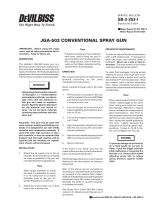
Figure 1
2
1
Apply sealant (Loctite #262)
to first two full threads.
12
8
10
6
9
5
3
4
7
11
Do not use abrasives such as a wire
brush or steel wool to clean the inside
of the non-stick lined cup. Damage
to the non-stick surface could result.
CLEANING
1. Disconnect spray gun from air supply.
2. Remove cup and empty paint, wipe clean
lid, fluid tube and inside cup.
3. Place a small quantity of solvent in the
cup. Replace and connect air supply to
gun. Spray solvent until clean.
4. Disconnect spray gun from air supply.
Remove cup and empty surplus solvent,
wipe clean with a lint free dry cloth.
5. Spray solvent into the bottom and side
holes of the check valve. Do not direct
air pressure higher than 15 psi through
or at the check valve. This may damage
the valve. The check valve can be re-
moved for cleaning if needed. It cannot
be disassembled. Allowing paint to dry
on the ball or seat surfaces may cause
the check valve not to function properly.
6. Spray solvent into the poppet stem hole.
To prevent sticking, it must be cleaned
after each use.
Note
The cam and mating surfaces on the
lid and yoke normally don't require
removal for cleaning. Spraying some
materials containing PTFE or similar
materials can necessitate more fre-
quent cleaning and possible disas-
sembly of the cam. The overspray
containing PTFE can build up on the
cam and mating surfaces causing a
condition where the cam may loosen
during use.
7. Clean cam and mating surface on lid with
a solvent soaked Scotch™ pad and blow
dry. If cam loosening persists, removal
of the yoke and cam will be required for
more thorough cleaning of these parts.
Again, use a solvent soaked Scotch™ pad
for this purpose. Reassemble lid.
IMMERSION
Since all materials in the cup are highly
solvent resistant, the cup assembly may be
immersed for cleaning. Immersion should
not exceed 24 hours. The use of paint strip-
pers should be avoided, because strippers
will affect the aluminum as well as other
non-metallic components. If the lid gas-
ket has become swollen from prolonged
exposure to solvents, it will return to its
original size without loss of properties when
allowed to dry.

EN
SB-4-367-K (10/2014)4 / 4
Finishing Brands reserves the right to modify equipment specications without
prior notice. DeVilbiss, Ransburg, BGK, and Binks are registered trademarks of
Finishing Brands. ©2014 Finishing Brands. All rights reserved.
WARRANTY POLICY
DeVilbiss products are covered by Finishing Brands one year materials and workmanship limited warranty.
The use of any parts or accessories, from a source other than Finishing Brands, will void all warranties.
For specic warranty information please contact the closest Finishing Brands location listed below.
DeVilbiss is part of Finishing Brands, a global leader in innovative spray nishing
technologies. For technical assistance or to locate an authorized distributor,
contact one of our international sales and customer support locations below.
USA/Canada
www.devilbiss.com
info@nishingbrands.com
Tel: 1-800-992-4657
Fax: 1-888-246-5732
United Kingdom
www.nishingbrands.eu
info@nishingbrands.eu
Tel: +44 (0)1202 571 111
Fax: +44 (0)1202 573 488
China
www.nishingbrands.com.cn
mkt@nishingbrands.com.cn
Tel: +8621-3373 0108
Fax: +8621-3373 0308
Mexico
www.nishingbrands.com.mx
sales@nishingbrands.com.mx
Tel: 011 52 55 5321 2300
Fax: 011 52 55 5310 4790
France
www.nishingbrands.eu
info@nishingbrands.eu
Tel: +33(0)475 75 27 00
Fax: +33(0)475 75 27 59
Japan
www.ransburg.co.jp
Tel: 081 45 785 6421
Fax: 081 45 785 6517
Brazil
www.devilbiss.com.br
Tel: +55 11 5641 2776
Fax: 55 11 5641 1256
Germany
www.nishingbrands.eu
info@nishingbrands.eu
Tel: +49 (0) 6074 403 1
Fax: +49 (0) 6074 403 281
Australia
www.nishingbrands.com.au
sales@nishingbrands.com.au
Tel: +61 (0) 2 8525 7555
Fax: +61 (0) 2 8525 7500
/