Page is loading ...

SB-4-391-R1 (5/2018) 1 / 4 www.carlisleft.com
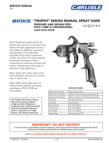
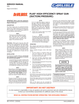
Figure 1
DESCRIPTION
Models: ■ TLC-555 – One quart capacity,
Non-stick coating lined cup
TGC-545 – One quart capacity
These drip free suction cups have a unique, two position valve which
permits selection of either a drip free spraying mode or a conventional
open vent mode.
In the drip free position, air is directed through the vent in the lid to a
channel beneath the lid gasket before entering the cup at the valve. This
allows the cup to be tilted when full without dripping paint through the
vent. The cup can also be inverted while spraying without leaking.
The open position isolates the channel and opens a direct vent into the cup.
The position of the valve is indicated by alignment of the hole in the valve
slot with the marks cast on the lid. These positions are identied as "O"
for vent open and "D/F" for Drip Free.
Note
Non-stick Coating Lined Cup - Only use a wooden or plastic paddle
or mixer for mixing material in the cup (7). A metal paddle or mixer
can scratch the non-stick coating.
Note
For Non-stick Coating Lined Paint Cups, variation in the color of
the non-stick coating is normal. This variation is the result of the
normal production process used with this type of coating. We have
selected this particular grade of non-stick coating because it provides
the best overall performance and maximum durability possible.
OPERATION
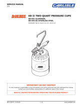
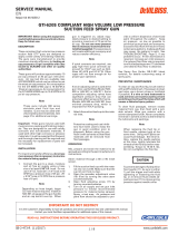
Open Vent Mode "O"- To operate in the open vent mode, rotate the
valve with a screwdriver or coin so that the hole in the valve slot is aligned
with the "O" on the lid. See Figure 2.
If the valve slot hole should plug while operating in the "O" vent mode,
use a pointed tool such as a nail or drill bit to probe through the valve
slot hole to clear away the obstruction.
Figure 2 – Open Vent Mode
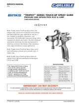
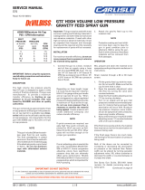
Drip Free Mode "D/F" – To operate in the drip free mode, rotate the
valve with a screwdriver or coin so that the hole in the valve slot is aligned
with the "D/F" on the lid. See Fig. 3
Do not probe through the channel vent hole at any time. Do
not probe through the valve slot hole while the valve is in the
"D/F" position. These holes are sealed by a gasket and
gasket damage could result. See Figs. 2 & 3.
Valve in Open Position
Channel
Vent Hole
(Do Not Probe)
Valve slot
hole can be
probed to clean.
Gasket
Channel
Channel
Vent Hole
Gasket shown
partially removed
Lid Top Lid Underside
D/F
O
Government NSN # 4940-01-208-8876 = TLC-555
Important: Before using this equipment, read all safety
precautions and instructions. Keep for future use.
IMPORTANT! DO NOT DESTROY
It is the Customer's responsibility to have all operators and service personnel read and understand this manual.
Contact your local DeVilbiss representative for additional copies of this manual.
READ ALL INSTRUCTIONS BEFORE OPERATING THIS DEVILBISS PRODUCT.
EN
SERVICE MANUAL
TLC-555 & TGC-545
DRIP FREE SUCTION CUPS

EN
SB-4-391-R1 (5/2018)2 / 4www.carlisleft.com
The following hazards may occur during the normal use of this equip-
ment. Please read the following chart.
HAZARD SAFEGUARDS
Solvents and coatings can be highly am-
mable or combustible, especially when
sprayed.
Do not spray near open ames, pilot lights in stoves or
heaters, or other heat sources.
Adequate ventilation must always be provided. Industrial
applications must comply with OSHA requirements.
During cleaning and ushing, solvents can
be forcefully expelled from uid and air
passages. Some solvents can cause eye
injury or irritation.
Wear eye protection.
Fire
Solvent Spray
CAUSE
Chlorinated solvents, such as 1, 1, 1 -
Trichloroethane and Methylene Chloride
(sometimes called methyl chloride) can
chemically react with the aluminum used
in most spray equipment, and these cups,
to produce an explosion hazard.
The TLC-555 and TGC-545 are aluminum.
Explosion Hazard -
Incompatible Materials
1. Read the label or data sheet for the material you
intend to spray.
2. Do not use any type of spray coating material con-
taining these solvents.
3. Do not use these solvents for equipment cleaning or
ushing.
4. If in doubt as to whether a material is compatible,
contact your material supplier.
Inhaling Toxic Substances Certain materials may be harmful if
inhaled, or if there is contact with the
skin.
Follow the requirements of the Safety Data Sheet sup-
plied by your coating material manufacturer.
Adequate exhaust must be provided to keep the air free
of accumulations of toxic materials.
Use a mask or respirator whenever there is a chance of
inhaling sprayed materials. The mask must be compatible
with the material being sprayed and its concentration.
Equipment must be as prescribed by an industrial hygien-
ist or safety expert, and be NIOSH approved.
SAFETY PRECAUTIONS
Important information to alert you to a situ-
ation that might cause injury or loss of life.
Important information that tells how to prevent
damage to equipment
This manual contains important information that ALL users should know and understand BEFORE using the equipment. This information relates to
USER SAFETY and PREVENTING EQUIPMENT PROBLEMS. To help you recognize this information, we use the following terms to draw your attention
to certain equipment labels and portions of this manual. Pay special attention to any label or information that is highlighted by one of these terms:
Note
Information that you should pay special attention to.
CA PROP
65
PROP 65 WARNING
WARNING: This product contains chemicals known to the State of California to cause
cancer and birth defects or other reproductive harm.

EN
SB-4-391-R1 (5/2018) 3 / 4 www.carlisleft.com
Valve Movement – Do not forcibly rotate the valve. If it will not move
freely, soak in solvent or remove the lid assembly from the cup and press
down on the top of the valve until it breaks free. The valve has free
travel vertically of about 1/8". This can be used to push out the gasket.
Figure 3 - Drip Free Mode
INSTALLATION
1. Position yoke at right angle to gun body with vent hole in lid toward
rear and lever of cam (3) toward front of gun.
2. Fasten cup lid assembly to gun by attaching nut (2), see Fig. 4, to
uid inlet nipple on gun. Tighten nut with wrench only until snug.
3. Strain material to be sprayed through a 60-90 mesh screen before
pouring into cup.
4. Engage pins on cup into yoke and tighten yoke by moving lever of
cam clockwise.
MAINTENANCE
Valve and Lid Gasket Replacement:
1. To remove a damaged valve (4) or lid gasket (5), press on top of
valve until it breaks free. The valve pushes the lid gasket from the
seat. The lid gasket may now be removed from the lid. Continue
pressing hard on the valve to remove it from the lid.
2. Install replacement valve (4) through bottom of lid so that the valve
tab is toward center of lid. Snap in place. If necessary, use a plastic
mallet or screwdriver handle to tap the valve in place. Press the lid
gasket rmly in the lid using the end of a crescent wrench. Insert
the side with the black marks rst.
CLEANING
Note
Always clean the cam lever (3) surfaces with clean solvent and a
brush. This will keep the cam lever functioning properly. Do not
lubricate the cam.
General: For routine cleaning, it is not necessary to remove the
lid gasket. It is not necessary or desirable to remove the valve for any
cleaning procedure. The valve can be depressed from the outside to
assist in removal of the gasket for gasket replacement or when cleaning
dried paint from the channel. The valve should not be forced past the
shoulder which retains it in the lid except for replacement.
Air Pressure: Always clean with reduced air pressure. An air pressure
no greater than 15 to 20 psi will allow quick and thorough cleaning of
the cup and gun and at the same time will:
1. Minimize the amount of solvent atomized into the air.
2. Prevent possibility of damage to cup from excessive back pressure.
3. Reduce the force with which solvent is expelled from the vent.
Cleaning Procedures:
1. Empty paint from cup and add small amount of clean solvent. The
amount required will vary with different coatings and solvents.
2. Shake cup to wash down inside surfaces. Then spray solvent at low
air pressure (15-20 psi) to ush out uid passages.
3. Pour out solvent and add same amount of clean solvent.
4a. Again, shake cup. Loosen air cap. Hold a folded cloth over front of
gun and invert cup over solvent receptacle. Trigger with short bursts
to back ush vent channel. With valve in D/F position, solvent will
be expelled with force from the channel vent hole in lid.
Alternative to Step 4a.
4b. Shut off air to gun. With valve in D/F position, invert cup over
solvent receptable. Trigger gun. Allow solvent to drip out channel
vent hole in lid for several seconds, or until clean solvent is seen.
Valve in Drip Free
Position
Channel
Vent Hole
(Do Not Probe)
Valve slot
hole sealed -
(Do Not Probe)
Lid Underside
D/F
O
Lid Top
Gasket shown
partially removed.
• Do not probe through the channel vent hole at any time.
Do not probe through the valve slot hole while the valve
is in the D/F position. These holes are sealed by gasket
(5) and gasket damage could occur.
• Do not use abrasives such as a wire brush or steel wool
to clean the inside of the non-stick coating lined cup (7).
Damage to the non-stick surface could result.
IMMERSION
Since all materials in the cup are highly solvent resistant, the cup assembly
may be immersed for cleaning. Immersion should not exceed 24 hours.
The use of paint strippers should be avoided because strippers will af-
fect the aluminum as well as other non-metallic components. If the lid
gasket has become swollen from prolonged exposure to solvents, it will
return to its original size without loss of properties when allowed to dry.
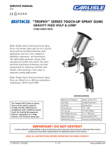
Parts List
Ind.
Ref. Replacement Parts
No. Part No. Description Req.
1 Adapter 1
2 Nut, 3/8" NPS (F) 1
3 Cam 1
4 TGC-407-1-K3 Drip Free Valve & Gasket (Kit of 3) 1
5 TGC-9-K5 **Tri Seal
®
Lid Gasket (Kit of 5) 1
6 Lid Assembly (Quart) 1
7 Suction Cup Assy. (Quart) 1
Sufx -K3 designates a kit of multiple parts. Example: TGC-407-1-K3 is a kit of
3 drip free valves.
** Registered Trademark of Tri-Seal International.
Apply sealant to
rst two threads
(Loctite #262).
7
1
2
3
4
5
6
Yoke
Figure 4
Keep
these
surfaces
clean.

EN
SB-4-391-R1 (5/2018)4 / 4www.carlisleft.com
WARRANTY POLICY
This product is covered by Carlisle Fluid Technologies’ materials and workmanship limited warranty.
The use of any parts or accessories, from a source other than Carlisle Fluid Technologies,
will void all warranties. Failure to reasonably follow any maintenance guidance provided
may invalidate any warranty.
For specic warranty information please contact Carlisle Fluid Technologies.
For technical assistance or to locate an authorized distributor,
contact one of our international sales and customer support locations.
Region Industrial/Automotive Automotive Renishing
Americas
Tel: 1-800-992-4657 Tel: 1-800-445-3988
Fax: 1-888-246-5732 Fax: 1-800-445-6643
Europe, Africa,
Middle East, India
Tel: +44 (0)1202 571 111
Fax: +44 (0)1202 573 488
China
Tel: +8621-3373 0108
Fax: +8621-3373 0308
Japan
Tel: +81 45 785 6421
Fax: +81 45 785 6517
Australia
Tel: +61 (0) 2 8525 7555
Fax: +61 (0) 2 8525 7575
Carlisle Fluid Technologies is a global leader in innovative nishing technologies.
Carlisle Fluid Technologies reserves the right to modify equipment specications without prior notice.
DeVilbiss
®
, Ransburg
®
, ms
®
, BGK
®
, and Binks
®
are registered trademarks of Carlisle Fluid Technologies, Inc.
©2018 Carlisle Fluid Technologies, Inc.
All rights reserved.
For the latest information about our products, visit www.carlisleft.com
/