Page is loading ...

D ESCENT i
user’s manual
TM

Serial Number ___________________________________
Record your serial numbers here for easy reference. You will need this information
when filling out your warranty registration. Descent i’s serial number is located near
the bottom of the backplate and also on the shipping container.
Descent i Settings:
Level ___________________________________________
25Hz Level ______________________________________
50Hz Level ______________________________________
Phase __________________________________________
Low Pass Filter ___________________________________
High Pass Filter: Out ______________________________
A/V Processor Bass Management Settings:
Main Speaker Size ________________________________
(large recommended for full range speakers)
Center Speaker Size ______________________________
(small recommended)
Surround Speaker Size ____________________________
(small recommended)
Level ___________________________________________
High-Pass _______________________________________
Low-Pass _______________________________________
WARNING! Do not use your Descent i loudspeakers outside of the country of original sale—voltage requirements
vary by country. Improper voltage can cause damage that will be potentially expensive to repair. The Descent i is
shipped to authorized MartinLogan distributors with the correct power supply for use in the country of intended
sale. A list of authorized distributors can be accessed at www.martinlogan.com or by emailing [email protected].
The lightning bolt flash with arrowhead symbol, within
an equilateral triangle, is intended to alert the user to
the presence of uninsulated “dangerous voltage” within
the product’s enclosure that may be of sufficient mag-
nitude to constitute a risk of electric shock.
The exclamation point within an equilateral triangle is
intended to alert the user to the presence of important
operating and maintenance (servicing) instructions in
the literature accompanying the appliance.
WARNING! Two people are required to move
this subwoofer.

Thank you—to you the MartinLogan owner,
for loving what we do,
and
for making it possible for us to do what we love.

4 Contents & Introduction
Contents & Introduction . . . . . . . . . . . . . . . . . . . . . . . . . 4
Installation in Brief . . . . . . . . . . . . . . . . . . . . . . . . . . . . . 5
Controls and Connections . . . . . . . . . . . . . . . . . . . . . . . 6
Accessing the Control Panel
Control Panel
Rear Connection Panel . . . . . . . . . . . . . . . . . . . . . . . . . . 8
2-Channel Mode . . . . . . . . . . . . . . . . . . . . . . . . . . . . . . . 9
Multi-Channel Mode . . . . . . . . . . . . . . . . . . . . . . . . . . . 10
2-Channel/Multi-Channel Mode . . . . . . . . . . . . . . . . . . 11
2-Channel Mode Using Speaker Level Inputs . . . . . . . . 12
2-Channel Mode With 2-Channel Output . . . . . . . . . . 13
Why the Filters Are Not Equal
Sub Out—Using Multiple Subwoofers . . . . . . . . . . . . . 14
AC Power Connection . . . . . . . . . . . . . . . . . . . . . . . . . . 15
Replacing the Fuse
Break-In
Placement. . . . . . . . . . . . . . . . . . . . . . . . . . . . . . . . . . . . 16
Listening Position
Installing In A Cabinet
Ask Your Dealer
Enjoy Yourself
Room Acoustics . . . . . . . . . . . . . . . . . . . . . . . . . . . . . . . 17
Your Room
Terminology
Solid Footing . . . . . . . . . . . . . . . . . . . . . . . . . . . . . . . . . 18
Home Theater. . . . . . . . . . . . . . . . . . . . . . . . . . . . . . . . . 19
MartinLogan Exclusives . . . . . . . . . . . . . . . . . . . . . . . . . 20
BalancedForce™ For Cleaner Bass
TriLinear™ Configuration
Servo-Controlled Dynamic Drivers
Proprietary Switching Amplifier
25Hz & 50Hz Level Control
Frequently Asked Questions & Troubleshooting . . . . 21
Dimensioned Drawings. . . . . . . . . . . . . . . . . . . . . . . . . 22
General Information . . . . . . . . . . . . . . . . . . . . . . . . . . . 23
Specifications
Warranty and Registration
Serial Number
Service
Glossary of Audio Terms . . . . . . . . . . . . . . . . . . . . . . . . 24
Notes . . . . . . . . . . . . . . . . . . . . . . . . . . . . . . . . . . . . . . . . 26
CONTENTS & INTRODUCTION
Congratulations! You have invested in one of the
world's premier subwoofers.
The MartinLogan Descent i represents the culmination
of an intensive, dedicated research program directed
toward creating a world class reference subwoofer using
advanced technologies and without compromising dura-
bility, reliability, craftsmanship or aesthetics.
The Descent i subwoofer uses three custom 10-inch
high-excursion drivers in a BalancedForce™, TriLinear™
configuration, which dramatically reduces cabinet
vibrations, allowing deep, tight, well-defined bass. Servo-
control woofer technology minimizes distortion. Three
proprietary digital amplifiers drive the output stage with
precision and extremely high efficiency. Low-pass filtering
and phase control have been designed to make integrat-
ing the Descent i subwoofer with both MartinLogan and
non-MartinLogan products both seamless and simple.
The materials in your new Descent i subwoofer are of the
highest quality and will provide years of enduring enjoyment
and deepening respect. The cabinetry is constructed from the
highest quality composite material for acoustical integrity.
This User's Manual will explain in detail the operation of
your Descent i subwoofer and the philosophy applied to
its design. A clear understanding will help you obtain max-
imum performance and pleasure from this most exacting
subwoofer system.
In accordance with the European Union WEEE (Waste
Electrical and Electronic Equipment) directive effective
August 13, 2005, we would like to notify you that this
product may contain regulated materials which upon
disposal, according to the WEEE directive, require spe-
cial reuse and recycling processing.
For this reason MartinLogan has arranged with our distrib-
utors in European Union member nations to collect and
recycle this product at no cost to you. To find your local
distributor please contact the dealer from whom you pur-
chased this product, email [email protected] or visit
the distributor locator at www.martinlogan.com.
Please note, only this product itself falls under the WEEE
directive. When disposing of packaging and other related
shipping materials we encourage you to recycle these
items through the normal channels.

Installation in Brief 5
We know you are eager to hear your new MartinLogan
subwoofer, so this section is provided to allow fast and
easy set up. Once you have your subwoofer operation-
al, please take the time to read, in depth, the rest of the
information in this manual. It will give you perspective on
how to attain the greatest possible performance from this
most exacting woofer system.
If you should experience any difficulties in the setup or
operation of your MartinLogan subwoofer, please refer
to the Room Acoustics and Placement sections of the
this manual. Should you encounter a persistent problem
that cannot be resolved please contact your authorized
MartinLogan dealer. They will provide you with the appro-
priate technical analysis to alleviate the situation.
WARNING!
• Hazardous voltages exist inside—do not
remove cover.
• Refer servicing to a qualified technician.
• To prevent fire or shock hazard, do not
expose this module to moisture.
• Turn amplifier off and unplug subwoofer
should any abnormal conditions occur.
• The power cord should not be installed,
removed, or left detached from the speaker
while the other end is connected to an AC
power source.
• The main power switch near the AC inlet shall
remain readily operable.
• No candles or other sources of open flame
should be placed on the speaker.
• No liquids either in glasses or vases should be
placed on speaker.
• Speaker should not be exposed to dripping or
splashing liquids.
• The terminals marked with the lightning bolt
symbol should be connected by an instructed
person or by way of ready made terminals
• The power cord should remain readily oper-
able should any abnormal conditions occur.
Step 1: Unpacking
Remove your new subwoofer from its packing. Note:
Retain original packing materials for future use.
Step 2: Placement
Ideally, place the subwoofer in a corner near the front of the
room. Please see the Placement section (page 16) for more
details.
Step 3: Signal Connection
Use the best cables you can. High quality cables, available
from your specialty dealer, are recommended and will
give you superior performance.
Attach your preamplifier/processor outputs through cables
to the signal input area located on the subwoofer’s rear
panel. Please see the Controls and Connections section
(pages 6–15) for more details.
If you plan to connect your subwoofer using Speaker Level
(high level) inputs, please refer to the 2-Channel Mode
Using Speaker Level Inputs section (page 12 for more
details.
Step 4: Power Connection (AC) (see warning)
Make sure the level knob is set at 0. Plug the subwoofer
into a wall outlet. Review the AC Power Connection section
(page 15) of this manual for more details.
Step 5: Setting the Controls
• Set the Level knob to 3 or 4.
• Set the Power switch to ‘Auto’.
• Set the 25Hz Level and 50Hz Level knobs to 0.
• Set the Phase to 90°.
• Set the Low Pass Filter to the closest setting below the
low-end frequency response of your main speakers.
These settings are only a beginning point. Your subwoofer
will need proper setup to optimize performance. Please
see the Controls and Connections section (pages 6–15) for
more details.
Step 6: Listen and Enjoy
INSTALLATION IN BRIEF

6 Introduction
CONTROLS AND CONNECTIONS
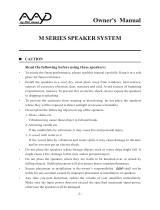
Figure 1. Top control panel.
The control panel is located behind the inset metal plate
located on top of the subwoofer. To access the control
panel, gently press the area above the MartinLogan logo.
When the spring releases gently pull the metal plate away
from the subwoofer.
Control Panel
Level
Setting the level too high will cause the bass to seem bloated
and is the single most common cause of bad sounding
subwoofers. A rule of thumb is that the subwoofer should
not draw attention to itself, but should simply make the
system’s low end seem more extended and accurate.
Low Pass Filter
When the Descent i is connected in multi-channel mode
(via its LFE input), the low pass filter is not active and your
processor handles the bass management. When connected
in 2-channel mode (via its speaker or line level left/right
input), the low-pass filter is active.
As a general rule the Low Pass Filter should be set at the option
approximately equal to (or below) 70% of your main speaker’s
lowest frequency response. Example: The MartinLogan Vista’s
lowest frequency response is 43Hz. 70% of 43Hz equals
30.1, so you should set the Descent i’s low pass filter to 30Hz.
Remember, this is a general rule. We advise that once you
try the recommended setting using the formula above, you
should try the surrounding settings to see which sounds best.
Optionally, an internal module in the Descent i can be
upgraded with a custom tailored Low Pass Filter setting
for use with the MartinLogan CLX loudspeaker. When this
upgrade is implemented the 30 Hz setting on the Descent
i becomes the CLX Low Pass Filter setting.
Phase Control
The phase control is entirely dependent on the size and
Accessing the Control Panel

Controls and Connections 7
configuration of your listening environment, the placement
of the unit, and your seating arrangement. Due to the way
bass sound waves develop in different rooms, there is no rule
of thumb for setting phase. For instance, if your room has
a peak at the subwoofer crossover area, you may wish to
set the phase so the actual acoustic outputs of the subwoofer
and main speakers are out of phase. Experiment, try dif-
ferent settings and be patient.
Power
The Auto/On/Standby switch controls Descent i’s energy
saving feature. When set to 'Auto', the Descent i will turn
on when a music signal is detected and off when there is
none. The 'On' setting prevents the Descent i from enter-
ing energy saving mode. The 'Standby' setting forces the
Descent i into energy saving mode. While set to 'Standby’,
the Descent i will not operate.
25Hz & 50 Hz Level
The 25Hz & 50Hz Level knobs significantly adjusts fre-
quencies where peaks and dips of different amplitudes
often manifest in real world environments. The ideal set-
ting is dependent on room size and construction, system
configuration and personal preference.
High Pass Filter: Out
The High Pass Filter: Out control filters the signal output
from the Right Out and Left Out connections.
Status Light
See descriptions of the status light on page 8. The top con-
trol panel status light functions identically to the back plate
status light.
Figure 2. Graphs demonstrating the frequencies effected by the 25Hz
Level and 50Hz Level controls

8 Controls and Connections
Sub Out
For systems utilizing multiple
subwoofers. Connect Sub Out
to the LFE Input or Right In /
Left In on additional sub(s).
Right Out / Left Out
Should only be used if con-
necting this sub between
a pre-amp and amplifier.
Connect to the Left In/Right
In on the amplifier. The High
Pass: Out control filters the
output from these connections.
LFE In (Balanced)
Connect to LFE Out on your
A/V processor. The subwoof-
er’s Low Pass Filter control
does not effect this connec-
tion. Crossover settings for LFE
In are controlled through the
A/V processor.
LFE In
Connect to LFE Out on your
A/V processor. The subwoofers
Low Pass Filter control does
not effect this connection.
Crossover settings for LFE In
are controlled through the A/V
processor.
Right In/Left In
Connect to Main-Out or
Pre-Out on your receiver/pre-
amp. Descent i’s Low Pass
Filter control effects the signal
received through these inputs.
Speaker Level In
This set of binding posts pro-
vides a place to connect the
subwoofer using standard
speaker cable. Descent i’s
Low Pass Filter control effects
the signal received through
these inputs.
Status Light
The Descent i is equipped
with a multi-color LED to
indicate the current sta-
tus of the woofers. The
following list explains the
meaning of the different colors:
No color: No power. The
subwoofer is not plugged in,
or the fuse has blown.
Green: Play mode. This indi-
cates the subwoofer detects
an audio signal and has auto-
matically switched into play
mode.
Yellow: Standby mode. This
indicates the Power switch is
set to Standby, or the sub has
detected no audio signal for
more than forty minutes and
has automatically switched
into standby mode.
Red: Initializing or Safe
mode. This indicates that the
subwoofer is initializing. This
also indicates if the subwoofer
temperature has exceeded
nominal operating range. If
the subwoofer overheats,
please allow it to cool and
reset it by unplugging the unit
and plugging it back in.
AC Power Connection, Master
Power Switch, & Fuse
Figure 3. Rear connection panel.
Rear Connection Panel

WARNING! Turn the Master Power switch Off
and unplug it before making or breaking any
signal connections!
2-Channel Mode
This setup is recommended if your subwoofer will be used
in a 2-channel only system. When a signal is connected to
the subwoofers Left In/Right In, the Low Pass Filter control
is active.
Signal Connection (see figure 4):
1 Connect the left out/right out from your preamp/receiver
to the Left In/Right In of the subwoofer. Use quality RCA
interconnects. If your preamp/receiver only has one set of
outputs you need to obtain Y adapters from your dealer.
Recommended Control Settings (see figure 5):
1 Calculate the number equal to 70% of your main loud-
speaker’s lowest frequency rating. Set the Low Pass Filter
switch to the closest setting below the resulting number.
2 Play familiar music with bass content. Increase the Level
control until the music has deep extended bass. Be
careful to avoid levels that become overwhelming.
3 Try the phase control in different settings until the best
blending is obtained. If you are using the subwoofer to
augment other MartinLogan products, we suggest start-
ing with the phase set at 90°.
4 If you have completed steps 1–3 and still have weak
or boomy bass, adjust the 25Hz Level and 50Hz Level
knobs to compensate for these anomalies. Experiment
with the controls and listen to the effects. Try to find
a position that sounds correct to you. Experiment by
changing the Level control while adjusting these knobs.
Find a position that gives you deep extended bass and
good blending with your main speakers.
Figure 4. Signal connection for 2-channel mode.
Figure 5. Adjust these controls for 2-channel mode.
Controls and Connections 9

Multi-Channel Mode
This setup is recommended if you will use your subwoofer
in a dedicated home theater or multi-channel system. When
a signal is connected to the subwoofer’s LFE In, the Low
Pass Filter control is NOT active. Your processor handles
most of the bass management.
Signal Connection (see figure 6—RCA shown):
1 Connect the LFE out of the processor to the LFE In. Use
either an RCA or an XLR interconnect.
WARNING!
Based on the performance of most processors,
it is recommended that MartinLogan center
and effects type speakers (i.e. Stage, Cinema,
Theater, and Script i) not be run in large, wide or
full range mode. Doing so may potentially dam-
age the speaker if the processor attempts to drive
the speaker beyond its rated frequency range.
This warning also applies to products from other
manufacturers.
It is recommended to run center and effects type
speakers in limited or narrow mode.
Recommended Control Settings (see figure 7):
1 With multi-channel source material playing, adjust the
Level control to your preferred level.
2 Try the phase control in different settings until the best
blending is obtained. If you are using the subwoofer to
augment other MartinLogan products, we suggest start-
ing with the phase set at 90°.
3 If you have completed steps 1–2 and still have weak
or boomy bass, adjust the 25Hz Level and 50Hz Level
knobs to compensate for these anomalies. Increase and
decrease to controls and listen to the effects. Try to find
a position that sounds correct to you. Experiment by
changing the Level control while adjusting these knobs.
Find a position that gives you deep extended bass and
good blending with your main speakers.
4 Follow the bass management setup instructions in your
processor manual to fine-tune the subwoofer level.
Figure 6. Signal connection for multi-channel mode.
Figure 7. Control settings for multi-channel mode.
10 Controls and Connections

This setup is recommended if your subwoofer will
be used in both 2-channel mode and as a LFE chan-
nel in a multi-channel system. By following this setup,
you will allow your processor to handle most of the
bass management while running in multi-channel
mode, and relinquish control of the low pass filter to
the subwoofer when running in a 2-channel mode.
Signal Connection (see figure 8):
1 Connect the left and right out of your preamplifier to
the subwoofer’s Left In / Right In. Use quality RCA
interconnects. If your preamplifier only has one set of
outputs you need to obtain Y adapters from your dealer.
2 Connect the LFE output of the processor to the sub-
woofer’s LFE In. Use quality RCA interconnects.
Recommended Control Settings (see figure 9):
1 Set your front speakers for wide, large or full mode in
your processor. Set the center and effects type speakers in
limited or narrow mode (see the warning on page 10).
2 Calculate the number equal to 70% of your main loud-
speaker’s lowest frequency rating. Set the Low Pass Filter
switch to the closest setting below the resulting number.
3 While playing familiar music with bass content, turn
the level control up until the music has deep bass that
is not overwhelming.
4 Try the phase control in different settings until the
best blending is obtained. If you are augmenting
MartinLogan loudspeakers, we suggest you start with
Phase set at 90°.
5 Use the bass management section of your processor’s
speaker setup to set the subwoofer level at an appro-
priate level. Follow the instructions in your processor’s
manual to fine-tune the subwoofer level.
6 If your processor offers the option to setup crossovers for a
subwoofer, we recommend that you start with the fol-
lowing settings—Crossover: 70Hz, High-Pass: 12dB,
and Low-Pass: 24dB. The optimal setting for these
options may vary depending on your room and listen-
ing preferences.
2-Channel/Multi-Channel Mode
Figure 8. Signal connection for 2-channel/multi-channel mode.
Figure 9. Control Settings for 2-channel/multi-channel mode.
Controls and Connections 11

This setup is recommended if your subwoofer will be used in
a 2-channel only system with full-range front loudspeakers.
When a signal is connected to the subwoofer’s Left In/Right
In subwoofer’s Low Pass Filter control is active.
Signal Connection (see figure 10):
1 Connect the left and right outputs of your amplifier to
the subwoofer’s high-level Speaker Level In (Left In/Right
In) binding posts. Use quality speaker cable.
If your amplifier only has one set of outputs you may
connect your amplifier to your speakers as normal and
run an additional set of cables from your speakers to the
subwoofer’s Speaker Level In binding posts.
It is also possible to connect the left and right outputs
of your amplifier to the left and right speaker level (high
level) inputs of the subwoofer and run an additional set
of cables from your subwoofer to the speakers.
Recommended Control Settings:
1 Set the controls as recommended on page 9.
2-Channel Mode Using Speaker Level Inputs
Figure 10. Signal connection for 2-channel mode using speaker level inputs.
12 Controls and Connections

This setup is recommended if your subwoofer will be used
in a 2-channel only system.
Signal Connection (see figure 11):
1 Connect the left out/right out from your preamplifier to
the Left In/Right In of the subwoofer. Use quality RCA
interconnects.
2 Connect the Left Out/Right Out of your subwoofer to
the left in/right in of your amplifier. Use quality RCA
interconnects.
Recommended Control Settings:
1 Set the controls as recommended on page 9.
2. The High Pass Filter: Out switch should be set, at the
user’s discretion, to the option with the best sound-
ing result. As a general rule, if your main loudspeakers
are bookshelf speakers, set the High Pass Filter: Out to
70Hz. Likewise, 40Hz for floorstanding loudspeakers.
Use ‘None’, if you want to pass an unaltered signal.
3 At this time the Low Pass Filter should be set to
approximately 70% of your main loudspeakers lowest
frequency response—make note of this number.
If the High Pass Filter: Out is set to ‘None’, the Low
Pass Filter should remain at approximately 70% of your
loudspeakers lowest frequency response.
If the High Pass Filter: Out is set to 40Hz, the Low Pass
Filter should be set to 35Hz or 70%, whichever is greater.
If the High Pass Filter: Out is set to ‘70Hz’, the Low Pass
Filter should be set to 55Hz or 70%, whichever is greater.
Why the Filters Are Not Equal
You may have noticed the recommended setting proce-
dure does not advise setting the Low Pass Filter and High
Pass Filter: Out to the same frequency. Between 20Hz
and 100Hz, as the subwoofers output decreases, the
loudspeakers output increases. For a seamless crossover
of these two slopes, the summation of their two values, at
any given frequency, should add to maintain a level out-
put. By correctly setting your High Pass Out and Low Pass
filters, this result can easily be achieved (see figure 12).
Figure 11. Signal connection for 2-channel mode with 2-channel output.
2-Channel Mode With 2-Channel Output
Figure 12.
Controls and Connections 13

Using Sub Out offers an easy way to implement multiple
subwoofers in your audio/video system.
Note: Additional subwoofers must run as either dedicated
2-channel (stereo) or multi-channel (LFE) subwoofers, but
not both.
Signal Connection:
1 Connect the first subwoofer to your system using one
of the five modes previously described.
2 Connect the Sub Out of the first subwoofer to either the
LFE In or the Right (or Left) In of the next subwoofer.
Use quality RCA interconnects.
Connecting to the LFE In allows additional subwoofers
to perform as dedicated LFE channels (see figure 13).
Connecting to the Right (or Left) In allows addition-
al subwoofers to perform as dedicated 2-channel
subwoofers (see figure 14).
3 Repeat step 2 for each additional subwoofer in the chain
using the same input for every additional connection.
Recommended Control Settings:
1 Adjust the control settings of the first subwoofer using
one of the five modes previously described.
2 Adjust the control settings of each additional subwoofer.
Use the method used to adjust the first subwoofer.
Note: While the settings of each subwoofer should be
similar, you will probably find that each sub will need
to be tweaked for optimal performance because of its
unique room placement.
Regardless of how you use your subwoofer, experimenta-
tion can often result in better sound. Don't be afraid to
try different settings. You can always return the controls to
their previous settings.
Sub Out—Using Multiple Subwoofers
Figure 14. Using multiple Descent i. Right/Left option.. Primary sub on
right. Additional sub on left.
14 Controls and Connections
Figure 13. Using multiple Descent i. LFE option. Primary sub on right.
Additional sub on left.

AC Power Connection
Figure 15. Descent i’s Master Power switch, Fuse, and AC Power receptacle.
Replacing the Fuse
WARNING! The power cord should not be
installed, removed, or left detached from the
subwoofer while the other end is connected to
an AC power source.
The IEC cord should be firmly inserted into the AC power
receptacle on the rear connection panel of the subwoofer,
then to any convenient AC wall outlet. Directly adjacent
to the AC power receptacle on the rear connection panel
of the subwoofer is a master power switch. This switch is
wired directly to the AC main and turns on/off all power
going to the subwoofer. The Descent i also integrates a
signal sensing power supply that will go to Standby mode
after a few minutes of no music signal if the front-panel
power switch is set to 'Auto'.
Your subwoofer is wired for the power service supplied in
the country of original consumer sale. The AC power rat-
ing applicable to a particular unit is specified both on the
packing carton and on the serial number plate attached
to the subwoofer.
If you remove your subwoofer from the country of original
sale, be certain that AC power supplied in any subsequent
location is suitable before connecting and operating
the subwoofer. Substantially impaired performance or
severe damage may occur to the subwoofer if opera-
tion is attempted from an incorrect AC power source.
If the fuse in your subwoofer should require changing,
turn your subwoofer off and unplug it before removing
the fuse. Replace the bad fuse (figure 15) with a matching
T 10A H 250V (T 5A L H 250V if you are in a region using
230v–240v mains voltage).
Break-In
Our custom made woofers require approximately 50
hours of break-in at moderate listening levels before their
optimal performance occurs. This will factor in on any
critical listening and judgment.
Controls and Connections 15
FUSE

Listening Position
Generally, subwoofers have the most output when placed
in the corner of a room. However, this can also exagger-
ate the subwoofers output making blending difficult. We
recommend starting by placing the subwoofer in a corner.
It should be placed in such a way that there are 2 inches
between the grill and the wall. This will avoid blocking
the output of any woofers. If, after the full range of tuning
techniques have been employed, the subwoofer sounds
like it has too much upper bass energy try pulling it away
from the wall, toward the listening position. This will less-
en the reinforcement of these problematic frequencies
from the wall and likely smooth out the response. Repeat
the setup procedure with the woofer controls after you
move it (see figure 16).
Installing in a Cabinet
It is common for people to place their subwoofer(s)
inside of cabinetry. The Descent i’s unique, three-woofer
design does not compromise the ability to be successfully
installed in such a configuration. However, it is recom-
mended, as with any quality multi-driver subwoofer, that
there be a minimum of three inches of open space
between the cabinet and the front, left and right sides (see
figure 17).
Ask Your Dealer
Your MartinLogan dealer can suggest many options for
optimal subwoofer placement. They also have many tools
at their disposal, such as experience, familiarity with the
associated equipment, and even sound analysis equip-
ment which may make the task of determining optimal
subwoofer placement easier.
Enjoy Yourself
The Descent i is a very refined subwoofer and will benefit
from care in setup. With the above placement tips in mind
you will find, over months of listening, that small changes
can result in measurable differences. As you live with your
subwoofer, do not be afraid to experiment with position-
ing until you find the optimal relationship between your
room, settings, and subwoofer that gives to you the best
results. Your efforts will be rewarded.
Figure 16. Descent i Subwoofers as the LFE (effects) channels, MartinLogan
Summit speakers as front channels, MartinLogan Stage as the center chan-
nel, MartinLogan Script i as side surround (effects) channels. Note the
corner placement of the Descent i at the front of the listening room.
Figure 17. Placing the Descent in a cabinet requires a minimum of three
inches of open space on the front, left and right.
16 Placement
PLACEMENT

Your Room
This is an area that requires both a little background to
understand and some time and experimentation to attain
the best performance from your system.
Your room is actually a component and an important part
of your system. This component is a large variable and can
dramatically add to or subtract from a great sonic experience.
All sound is composed of waves. Each frequency has its
own wave size, with the lower, or bass frequencies liter-
ally encompassing from 10 feet to as much as 40 feet. Your
room participates in this wave experience like a swimming
pool with waves reflecting and becoming enhanced depend-
ing on the size and shape of the room and the types of
surfaces in the room.
Remember that your audio system can actually generate
all of the information required to recreate a sonic event
in time, space, and tonal balance. Acoustically, the role of
an ideal room would be to neither delete nor contribute
to that information. However, nearly every room does to
some degree.
Terminology
Standing Waves
Sound coming from a subwoofer bounces around in a
room until a pattern emerges—this is called a standing
wave. Typically, this is only a problem with frequencies
below 100Hz. When this happens different parts of your
room experience either an excess or a lack of bass.
Some people believe that having a room without parallel
walls will eliminate this effect. The truth is that non-parallel
walls only generate different standing wave patterns than
those that occur in rectangular rooms.
Usually, you can excite most of the standing waves in a
room by putting the subwoofer in a corner. Listening
position determines which standing waves you will expe-
rience. For instance, if you sit in a corner you will hear
most of the standing waves. This can be an overpowering
experience. Sitting next to a wall can also intensify the levels
of the standing waves that are experienced.
Resonant Surfaces and Objects
All of the surfaces and objects in your room are subject to
the frequencies generated by your system. Much like an
instrument, they will vibrate and "carry on" in syncopation
with the music, and may contribute in a negative way to the
sound. Ringing, boominess, and even brightness can occur
simply because surfaces and objects are "singing along" with
your speakers.
Resonant Cavities
Small alcoves or closet type areas in your room can be
chambers that create their own "standing waves" and can
drum their own "one note" sounds.
Room Acoustics 17
ROOM ACOUSTICS

Solid Footing
After living and experimenting with your subwoofer, you
may want to use ETC (energy transfer coupler) spikes sup-
plied with the subwoofer (see figure 18). With the use
of these spikes, the subwoofer will become more firmly
planted on the floor and, consequently, bass will tighten
and imaging will become more coherent and detailed. It
is best not to implement the spikes, however, until you are
secure in the positioning, as the spikes can damage the
floor if the speaker is moved. The feet that attach to the
bottom of the Descent i use a common
3
/8 - 16 thread.
Spike Installation Instructions:
1 On a soft, padded surface, carefully lay your subwoofer
on its side to gain access to the bottom.
2 Remove existing feet or spikes. Thread new spikes into
holes and screw them in all of the way. If the subwoofer
does not sit level loosen one spike until level is achieved.
3 By hand, tighten the jam nut snugly against the cabinet.
Do not over tighten the nut.
4 Right the speaker.
Caution: Make sure your hands and any cabling are
clear of the spikes. Do not slide subwoofer as spikes
are sharp and can damage your floor or carpet.
5 Adjust to level by rotating spikes. By hand, tighten the
jam nut snugly against the cabinet when you are satis-
fied that subwoofer is level.
Caution: Walking the subwoofer may result in a broken spike.
18 Room Acoustics
Figure 18. The ETC™ Spike.

It had long been the practice of stereo buffs to connect
their television to the stereo system. The advantage was the
use of the larger speakers and more powerful amplifier of the
stereo system. Even though the sound was greatly improved,
it was still mono and limited by the broadcast signal.
In the late 1970's and early ‘80's two new home movie formats
became widely available to the public: VCR and laser disc.
At the same time video screen sizes began increasing.
By 1985, both formats had developed into very high qual-
ity audio/video sources. In fact, the sonic performance of
some video formats exceeded audio-only formats. Now,
with theater quality sound available at home, the only
element missing was the "surround sound" presentation
found in movie houses.
Fortunately, "Dolby" and "DTS" encoded material (which
include almost all movies) have the same surround sound
information encoded on home releases as the theater films.
All that is required to retrieve this information is a decoder,
additional speakers, subwoofer(s) and amps to reproduce it.
Home theater is a complex purchase and we recommend
that you consult your local MartinLogan dealer, who is well
versed in this subject.
Each piece of a surround system can be purchased sepa-
rately. Take your time and buy quality. No one has ever
complained that the movie was too real. The following list
and descriptions will only give you a brief outline of the
responsibilities and demands placed on each speaker.
Front Left and Front Right
If these speakers will also be the same two used for your stereo
playback then they should be of very high quality and able to
play loud (over 102 dB) and reproduce bass below 80 Hz.
Center Channel
Many experts believe this to be the most important speaker
in a home theater system, as almost all of the dialogue and
a large portion of the front speaker information is repro-
duced by the center channel. It is important that the
same manufacturer of the front speakers design the center
speaker and that it is recommended for use as a center
speaker. This is not the place to cut corners.
Surround Speakers
The surround, or effect speakers contain critical informa-
tion. In films, sound effects are vital to the director in
delivering a complete experience and the rapid technical
increase in the discreet capacity of these effects channels
has made their quality vital. This is equally true in music
play back because of the emerging high definition, multi-
channel music only formats. Full range instruments, voices
and ambient queues are being routed to the effects chan-
nel. In the past, some may have suggested that this was
the place to save money by purchasing small inexpensive
speakers. If you choose to do so, be prepared to upgrade
in the future.
Subwoofer
With any good surround system you will need one or more
high quality subwoofers (the .1, in a 5.1 channel surround
system). Most movie soundtracks contain large amounts
of bass as part of the special effects. Good subwoofers will
provide a foundation for the rest of the system.
Figure 19. Summit speakers as front channels, the Stage as the center
channel, Script i speakers as side surround (effects) channels, and
Descent i subwoofers as LFE (effects) channel.
Home Theater 19
HOME THEATER

Resulting from an equal and opposite reaction to the cone's
movement, strong bass causes all traditional subwoofer
enclosures to generate acoustic vibrations. You feel this by
touching the cabinet. Although the "physics" of this phe-
nomenon actually cause a subwoofer cabinet to resonate
or even dance, most subwoofer designers apply weight or
mass to the cabinet to minimize such disturbances, but still
leave one by product—"smeared bass". Vibrations translated
from the woofer to the cabinet actually dampen the bass
signal causing a loose and "fuzzy" sound.
The Descent i integrates BalancedForce bass configura-
tion to nullify cabinet vibrations. Originally engineered for
the cost-no-object, state-of-the-art Statement™ E2 system,
BalancedForce uses two or more drivers mounted at oppos-
ing angles. The Descent i's 3 drivers, spaced 120 degrees
apart, operate in exact opposition, resulting in maximum
cancellation delivering the ideal—pure bass energy with a
reduction in cabinet contributions to the room as high as
25dB over traditional subwoofer resonance solutions!
TriLinear™ Configuration
The use of three small, identical drivers maintains the low
distortion levels and optimal control of an efficient and
rigid small driver while moving the same amount of air as
a driver three times larger. This allows powerful bass in a
small package, free from the performance limitations of a
heavy and hard to control single large driver.
Servo-Controlled Dynamic Drivers
All dynamic drivers generate distortion caused by spider
and surround nonlinearities as well as voice coil inductive
disturbances and variant motor strength during massive
woofer excursions. These challenges plague all subwoofer
designers. The result? Induced harmonic and intermodulated
distortions causing dramatic disturbances at high excursions.
This occurs significantly in almost all non-servo-controlled
subwoofers.
MartinLogan’s advanced servo system uses a sophisticated
monitoring and control circuit to detect and instantaneous-
ly correct any deviation between acoustical output and
electrical input. The result? A reduction in distortion for
the purest possible low-frequency reproduction.
Proprietary Switching Amplifier
The Descent i incorporates three identical proprietary
switching amplifiers.The use of three amplifiers allows
for an incredible amount of woofer control resulting in
tighter, better defined bass while keeping distortion at the
lowest possible levels.
25Hz & 50Hz Level Control
The Descent i 25Hz & 50Hz Level controls allows custom
sound tailoring capabilities found in few subwoofers. A
room, especially when small, can greatly exaggerate bass
in the 20–60Hz range. The Descent i’s 25Hz & 50Hz
Level control knobs increase or decrease lower bass to
compensate for these room anomalies and allow increased
deep bass if you desire a subsonic sense of energy at the
lowest frequencies.
20 MartinLogan Exclusives
MARTINLOGAN EXCLUSIVES
BalancedForce™ For Cleaner Bass
/