Page is loading ...

TAL 1211 (L) Rev. 2 © MSA 2012 Prnt. Spec. 10000005389(A) Mat. 10090073
Doc. 10090073
CRANBERRY TWP.,PENNSYLVANIA,U.S.A.16066
For More Information, call 1-800-MSA-2222 or VisitOurWebsiteatwww.MSAsafety.com
Changes and modifications not expressly approved by the manufacturer could void the
User’s authority to operate the equipment.
The warranties made by MSA with respect to the product are voided if the product is not
installed, used and serviced in accordance with the instructions in this manual. Please pro-
tect yourself and your employees by following the instructions. Please read and observe the
WARNINGS and CAUTIONS inside. For any additional information relative to use or repair,
write or call 1-800-MSA-2222 during regular working hours.
This manual must be carefully read and followed by all persons who have, or will
have, the responsibility for upgrading this air mask. This air mask will perform as
designed only if upgrading according to the instructions. Otherwise it could fail to
perform as designed, and persons who rely on the air mask could sustain serious
personal injury or death.
UPGRADE INSTRUCTIONS
FireHawk
®
M7
Air Mask
NFPA 1981 - 2007 Edition Compliant
The FireHawk M7 Control Module, Power Module, and HUD Receiver comply with
Part 15 of the FCC Rules.
Operations are subject to the following conditions:
(1) This device may not cause harmful interference and
(2) This device must accept any interference that may cause undesired
operation.
DO NOT use a 2216psi air cylinder on a 3000psi operating system. Such a configuration
is not approved by NIOSH. Failure to follow this warning can result in serious personal
injury or death.

IMPORTANT NOTICE
THE UPGRADE OUTLINED IN THE MANUAL MUST
ONLY BE PERFORMED BY C.A.R.E. TRAINED AND
CERTIFIED TECHNICIANS.
A thorough understanding of the air mask is essential
before attempting to service or maintain it. A user's
instruction manual, P/N 10082858, is supplied with this
kit. Refer to the user's instructions for specific user infor-
mation, such as NIOSH Approval Information, donning
and doffing instructions, and cleaning and disinfecting
procedures.
This air mask will perform as designed only if used and
maintained according to the manufacturer's instructions.
You must read and understand these instructions before
trying to use or service this product. We encourage our
customers to write or call for information on this product
before using it.
Inspect the air mask regularly and maintain it according to
the manufacturer's instructions.
If the air mask does not perform as specified in this man-
ual, it must not be used until it has been checked by
authorized personnel.
Do not alter, modify, or substitute any components with-
out the approval of the manufacturer. Such alterations will
void the NIOSH approval.
NFPA 1981, 2002 EDITION COMPLIANCE INSPECTION
DO NOT inspect the apparatus before cleaning if there
is a danger of contacting hazardous contaminants.
Clean and sanitize first, then inspect. Failure to follow
this warning can cause inhalation or skin absorption
of the contaminant and result in serious personal
injury or death.
An SCBA cannot be upgraded until the following
inspection and all required changes have been com-
pleted.
Inspect the entire air mask after it is cleaned and sani-
tized. NFPA-1500, as well as ANSI Standards Z88.2 and
Z88.5, describe three levels of inspection procedures that
are to be performed. Refer to these documents or to an
inspection program prepared by a health professional in
establishing an inspection program.
Note: An NFPA 1981, 2002 edition compliant air mask
will have the URC fitting on the Audi-larm™ Audible
Alarm, Heads-Up-Display (HUD) Receiver and HUD
Transmitter or an ICM Tx or ICM TxR Integrated PASS.
Prior to installation of the FireHawk M7 Upgrade Kit, the
air mask must be upgraded to be compliant with the 2002
Edition of the NFPA-1981 Standard. The components
must be in good working order and free of damage or sig-
TABLE OF CONTENTS
Important Notice .....................................................................................................................................................................2
NFPA 1981, 2002 Edition Compliance Inspection..................................................................................................................2
Inspection and Functional Test of the 2002 NFPA Compliant Air Mask.................................................................................3
Cylinder Inspection .................................................................................................................................................................4
Facepiece Upgrade.................................................................................................................................................................4
Removing the component housing cover ........................................................................................................................4
Converting the facepiece from ¼ Turn MMR to Firehawk Regulator...............................................................................7
Installation of the FireHawk M7 HUD Bracket..................................................................................................................7
Firehawk Adapter and Cover Installation .........................................................................................................................8
Removing the head harness.............................................................................................................................................8
Installation of facepiece model number labels.................................................................................................................9
Installing the FireHawk M7 HUD .............................................................................................................................................9
Removing the Pressure Gauge or PASS Device.....................................................................................................................9
Salvaging Parts from the Current Carrier and Harness ........................................................................................................10
Removing the First Stage Regulator from the Carrier and Harness.....................................................................................11
First Stage Regulator Upgrade .............................................................................................................................................11
High Pressure Gauge Hose Upgrade....................................................................................................................................12
Installing Soft Goods on the Carrier and Harness Assembly ...............................................................................................13
Installing the FireHawk M7 Control Module..........................................................................................................................15
Installing the FireHawk M7 Power Module ...........................................................................................................................18
Second Stage Regulator Upgrade ........................................................................................................................................18
Installing the First Stage Regulator.......................................................................................................................................18
Leak Testing ..........................................................................................................................................................................19
Functional Test ......................................................................................................................................................................19
Flow Test Requirements........................................................................................................................................................20
TAL 1211 (L) Rev. 2 - 10090073
2
INTRODUCTION

nificant wear. Some accessories and components may
not be approved for use on an NFPA 1981, 2007 edition
compliant unit. Consult the NIOSH approval label
(P/N10083874) included in the upgrade kit for a complete
list of approved components.
If any component of the air mask being upgraded is
missing or needs to be replaced due to wear or dam-
age, replace the affected component before installing
the FireHawk M7 Upgrade Kit. Used, worn, or dam-
aged parts can result in serious personal injury or
death.
INSPECTION AND FUNCTIONAL TEST OF THE NFPA
1981, 2002 EDITION COMPLIANT AIR MASK
In addition to the inspection of components required prior
to the updgrade, the following general inspection of the
apparatus must be performed before installing the
FireHawk M7 Upgrade Kit.
1. Don the air mask following the instruction proce-
dures. These steps make up the air mask
functional test.
2. If all steps are performed successfully, remove the air
mask and inspect it following the steps below.
3. Facepiece
a. Inspect the facepiece for rubber deterioration,
dirt, cracks, tears, holes, or tackiness.
b. Check the harness head straps for breaks, loss
of elasticity, or missing buckles or straps. Check
the straps for signs of wear.
c. Inspect the lens for cracks, scratches, and a tight
seal with the facepiece rubber.
d. The exhalation valve must be clean and operate
easily. Reach into the facepiece. Push and
release the valve stem several times. The valve
must move off the seat and return when released.
e. Inspect the facepiece inlet regulator coupling for
damage. Also check to be sure that the spider
gasket and valve disc are present, clean, and not
damaged.
f. Inspect the facepiece rubber behind the
Nightfighter Heads Up Display receiver bracket
or Clear Command bracket for holes or tears.
4. Cylinder Gauge
a. Be sure that the gauge needle and face is visible
through the lens.
b. Be sure the gauge stem is not bent.
5. Audible Alarm with URC Assembly
a. Check that the alarm rings briefly when the
cylinder valve is opened.
b. Check that the bell is in the proper alignment and
is fastened securely.
c. If the bell is loose, remove the alarm from service.
d. Unscrew the Audi-Larm Audible Alarm with URC
Assembly coupling nut from the cylinder valve. In-
spect the coupling nut for thread damage. Also be
sure there is an o-ring, and that it is not damaged.
Replace the insert o-ring if it is damaged.
e. Check Audi-Larm Alarm with URC Assembly and
URC Assembly relief valve for any damage.
f. Check relief valve label for damage. Check for
missing or lose label. Ensure that relief valve
ports are showing. If any damage, remove air
mask from service and replace relief valve.
6. High Pressure Hoses
a. Check the high pressure hose between the Audi-
Larm Audible Alarm and the first stage regulator.
Look for cuts or severe abrasions. If present,
replace the hose. The hose should be securely
attached to the first stage regulator and Audi-Larm.
b. Check the high pressure hose between the remote
gauge and the first stage regulator. Look for cuts or
severe abrasions. If present, replace the hose.
7. Intermediate Pressure Hose Inspection
a. Inspect the intermediate pressure hose between the
first stage regulator and the second stage regulator.
The hose must be free of severe abrasions, wear,
cuts or damage.
b. Inspect the connection between the first stage inter
mediate pressure hose and the second stage inter
mediate pressure hose. The hoses should swivel
easily. The connection should be free of damage.
c. Inspect rubber washer for deterioration, dirt, cracks,
tears, or tackiness.(for quick connect hoses only)
8. Cylinder
a. Inspect the cylinder valve for signs of damage.
The valve may be opened slightly to be sure it
operates properly. Be sure to fully close the valve.
b. Inspect the cylinder body for cracks, dents,
weakened areas, or signs of heat-related
damage. If the cylinder is damaged, return it to
an MSA service Center. Call 1-800-MSA-2222
for instructions.
Note: Check the hydrostatic test date on the cylinder
approval sticker located on the cylinder neck. Composite
cylinders must be tested every three years.
After all inspections have been completed successfully,
install the FireHawk M7 Upgrade Kit
Only MSA certified technicians are authorized to
install the NFPA 2007 Upgrade Kit.
TAL 1211 (L) Rev. 2 - 10090073
3
INTRODUCTION

INTRODUCTION
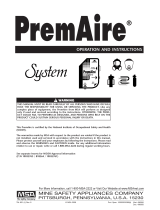
CYLINDER INSPECTION
The following model numbers are approved for use on the
FireHawk M7 Air Mask.
Note: Aluminum and steel cylinders are not approved for
use with the FireHawk M7 Air Mask.
FACEPIECE UPGRADE
The facepiece upgrade will vary depending on the config-
uration of the air mask facepiece being upgraded. The fol-
lowing is a description of CBRN approved configurations:
• Ultra Elite
®
Facepiece models 7-935-4, 7-935-5, or
7-935-6 may be upgraded to be NFPA 1981, 2007
Edition Compliant with the following exceptions.
o The 5-point rubber head harness and SpeeD-ON
®
Head Harness are not CBRN approved. Users that
have the 5-point rubber or SpeeD-ON Head
Harnesses must install the 4-point adjustable
SpeeD-ON Head Harness.
o Silicone Ultra Elite Facepieces are not CBRN
approved and cannot be upgraded. Users that have
silicone Ultra Elite Facepieces must use a new
CBRN Ultra Elite Facepiece.
o The Ultra Elite Facepiece baffle is not CBRN
approved. A medium or large nosecup must be
installed.
• Ultra Elite Facepieces models 7-935-7, 7-935-8, or 7-
935-9 with nosecups and 4-point adjustable SpeeD-
ON Head Harnesses are CBRN approved.
The upgrade kit that was ordered should contain what is
needed to upgrade to a CBRN compliant Ultra Elite
Facepiece. The nosecup will not be part of the kit and
must be ordered separately if the facepiece being upgrad-
ed does not contain one.
The facepiece upgrade consists of installing the following
components depending on the kit that was ordered.
Note: If the kit includes a new facepiece, the facepiece
upgrade is completed. Proceed to “Installing the
FireHawk M7 HUD” section of this manual.
When upgrading from a 1/4-Turn Ultra Elite to Firehawk
Push-to-Connect Ultra Elite Facepiece, the following
components must be installed:
10033115 Push-to-Connect Inlet Adapter
489224 Push-to-Connect Facepiece Cover
10033208 Screws
490134 Spider Gasket
491933 Inlet Disc
10031102 4-Point Adjustable SpeeD-ON Head
Harness (if needed)
10051706 Model Number Labels
When upgrading from 1/4-turn Ultra Elite to Firehawk
Slide-to-Connect Ultra Elite Facepiece, the following com-
ponents must be installed:
10018621 Slide-to-Connect Inlet Adapter
10034500 Slide-to-Connect Facepiece Cover
10033208 Screws
490134 Spider Gasket
491933 Inlet Disc
10031102 4-Point Adjustable SpeeD-ON Head
Harness (if needed)
10051706 Model Number Labels
When replacing silicone Ultra Elite Facepieces, one of the
following facepieces must be used:
REMOVING THE COMPONENT HOUSING COVER
The following procedure outlines the steps required to
remove the component housing from the Ultra Elite
Facepiece. This step is necessary for all upgrades unless
a new facepiece was provided with the upgrade kit.
1. Remove the two component housing cover screws.
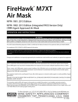
2. Remove the locking
ring, if applicable.
3. Remove the component housing cover.
a. For the 1/4 Turn Regulator: Lift up on the cover
release hook located forward of the adapter
4
TAL 1211 (L) Rev. 2 - 10090073
Model No.
Service
Volume Construction
Pressure
5-447-1 2216 psig 45 scf Carbon Fiber
7-1006-1 3000 psig 60 scf Carbon Fiber
7-947-1 4500 psig 45 scf Carbon Fiber
7-1348-1 4500 psig 66 scf Carbon Fiber
7-1537-1 4500 psig 88 scf Carbon Fiber
Size Slide-To-Connect Push-To-Connect
Small 10084689 10084690
Medium 10084823 10084824
Large 10084827 10084828

assembly opening. Once the release is lifted,
remove the cover by pulling it away from the hous-
ing. Tilt the cover and work it over one adapter bay-
onet at a time.
b. For the Firehawk Slide-To-Connect Regulator:
Remove the cover by pulling it away from the hous-
ing.
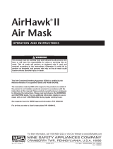
c. For the Firehawk
Push-To-Connect
Regulator: Pull the
cover to release the
retaining hook. With
the cover between
the hex flats and
flange of the adapter,
turn the adapter
counter-clockwise to
remove.
Be careful that you do not damage internal parts of
the comonent housing assembly (exhalation valve,
spring retainer, or speaking diaphragm) once the cover
is removed.
TAL 1211 (L) Rev. 2 - 10090073
5
INTRODUCTION

NOTES
6
TAL 1211 (L) Rev. 2 - 10090073

CONVERTING THE FACEPIECE FROM A 1/4 TURN
MMR TO FIREHAWK REGULATOR
This procedure outlines the steps required to remove the
¼ Turn MMR adapter from the Ultra Elite facepiece and to
replace the spider gasket. If the facepiece being upgraded
is already configured for the Firehawk Regulator, this step
may be skipped.
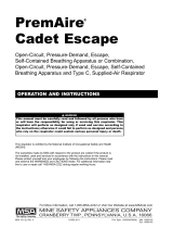
1. Unthread and remove
the old adapter assem-
bly.
2. Remove the old spider gasket from the facepiece
inlet by pulling up on the spider gasket pull-tab and
pulling the spider gasket out of the facepiece inlet.
Replacing the Spider Gasket
1. Install a new inlet disc on the stem of the new spider
gasket by working the hole in the center of the inlet
disc over the spider gasket stem.
2. Note that the inlet gasket has a groove around it.
3. With the pull-tab facing you, insert the spider valve
into the facepiece at an angle so that its groove cap-
tures the housing rim. The lower lip on the spider
valve must be placed under the rim in the component
housing.
Note: It may be necessary to bend the spider valve slight-
ly to work the groove under the rim all the way around.
When installed correctly, the spider valve will lay flat in the
housing and none of the spokes will be bent.
INSTALLATION OF FIREHAWK M7 HUD BRACKET
Removing the NFPA 2002 HUD Bracket
1. Remove the Nightfighter Heads-Up-Display from the
facepiece and discard.
2. Remove the screw from right side of the facepiece
lens-retaining ring.
3. Remove the component housing cover. Refer to
“Removing the Component Housing” section of the
Facepiece Upgrade portion of this manual if compo-
nent housing has not yet been removed.
4. Remove the mounting bracket and discard.
Installation of the new Firehawk M7 HUD Mounting
Bracket to the facepiece
1. Slide the new bracket assembly onto the facepiece.
a. Make sure that
molded tab is under
the lower lens ring.
2. Align the upper tab
screw hole with the
upper lens-ring screw
hole.
3. Reinstall the screw.
a. Make sure that the
screw goes through
the hole in the upper
metal tab.
4. Align the screw hole in
the lower metal tab
with component hous-
ing screw hole.
5. Reinstall the component housing cover.
6. Check alignment and tighten screws
TAL 1211 (L) Rev. 2 - 10090073
7
UPGRADE INSTRUCTIONS

FIREHAWK ADAPTER AND COVER INSTALLATION
The following steps outline the procedure for installing the
Firehawk second stage regulator adapter and component
housing cover.
Note: The following pictures show a push-to-connect
style adapter and component housing cover. If a slide-to-
connect adapter is being used, the installation procedure
is the same but a different adapter and cover will be used.
1. Screw the adapter assembly into the facepiece.
a. Ensure that the top
flat is perpendicular
to the centerline.
2. Place the component housing cover over the adapter
assembly.
3. Insert the tab on the
cover into the slot in
the lens ring.
4. Press the cover until it locks.
Note: If necessary, use a
small slot head screwdriver
to engage the cover.
5. Place the neck strap brackets into the sockets
(optional).
a. Install Phillips screws
and tighten.
7. Don the facepiece and check the face-to-facepiece
seal.
REMOVING THE HEAD HARNESS
If the facepiece being upgraded has a 4-point adjustable
SpeeD-ON Head Harness, this step may be skipped. The
5 point adjustable Speed-ON Head Harness must be
replaced.
1. Pull the ends of the head harness straps out of the
metal buckles.
2. Remove the top metal buckle from the facepiece.
Installing the 4-point adjustable head harness
1. Place the top buckle of the 4-point adjustable head
harness onto the facepiece.
2. Thread the four remaining side and bottom straps
through the buckle.
3. Ensure that the straps are correctly oriented and they
grip the straps when tightened.
4. Don the facepiece and check the face-to-facepiece
seal. Follow the Facepiece Fit Check procedures in
the FireHawk M7 Air Mask Operation and Instruction
Manual (P/N 10082858).
TAL 1211 (L) Rev. 2 - 10090073
8
UPGRADE INSTRUCTIONS

INSTALLATION OF FACEPIECE MODEL NUMBER
LABELS
If the facepiece has been upgraded or if it does not have
the model number described below, a new model number
label must be applied to the facepiece. New CBRN compli
ant facepieces will have the new model number engraved
on them and a label will not be required.
Identify the facepiece model number label from the set of
three facepiece labels.
This table identifies the proper model number label.
Apply the label to the
inside of the facepiece at
the bottom left of the lens.
Discard the remaining
unused labels. Ensure that
the model number is ori-
ented properly and can be
clearly seen from the out-
side of the lens.
INSTALLING THE FIREHAWK M7 HUD
Note: Once the facepiece has been upgraded, and HUD
mounting bracket installed, the FireHawk M7 HUD is
ready to be mounted to the facepiece.
1. Insert three AAA alkaline batteries in the appropriate
locations on the battery cartridge. Follow the notations
on the cartridge to ensure proper battery orientation.
2. Insert the battery cartridge into the battery tube on the
FireHawk M7 HUD.
3. Before installing the battery cap, verify that the o-ring
is in place and free of damage and debris. If the o-ring
is missing or damaged, replace o-ring. Failure to do so
may allow moisture or contaminants into the battery
tube and cause the device to not function properly.
4. Thread the battery cap on to the battery tube of the
FireHawk M7 HUD (clockwise). Hand-tighten cap until
snug. Do not over-tighten battery cap.
5. As the battery cap makes contact with the battery car-
tridge, verify that the FireHawk M7 HUD display turns
on and goes through its start up sequence before
turning off. The yellow LED should not be flashing.
Use only Rayovac 824 LR03, Rayovac Ultrapro 4R03,
Energizer E92, Energizer Industrial EN92, Duracell
MN2400, or Duracell Pro Cell MN2400 alkaline batter-
ies in the FireHawk M7 HUD. Use of other batteries, or
a combination of batteries from different manufactur-
ers, will affect the performance of unit and void the
Intrinsic Safety Approval.
Attaching the FireHawk M7 HUD to the Mounting
Bracket
1. Align the metal tab on
the FireHawk M7 HUD
with the metal plate on
the front edge of the
bracket.
2. Rotate the M7 HUD so
that the tab fits into the
slot behind the thumb-
screw.
3. Finger tighten the thumbscrew.
DO NOT use a screwdriver to tighten the thumbscrew.
REMOVING PRESSURE GAUGE OR INTEGRATED
PASS DEVICE
Before starting the procedures below, be sure that the
cylinder valve is completely closed. Be sure that nothing
blocks the regulator outlet. Open the bypass valve to
relieve any pressure in the system. Failure to follow this
warning can result in serious personal injury or death.
Facepiece
Style Size
Model No.
7-935-7 Ultra Elite Medium
7-935-8 Ultra Elite Small
7-935-9 Ultra Elite Large
TAL 1211 (L) Rev. 2 - 10090073
9
UPGRADE INSTRUCTIONS

1. Loosen and remove the pressure gauge or integrated
PASS from the high pressure gauge hose. Discard
gauge.
2. Using the o-ring removal tool, remove and discard the
o-ring and back-up ring from the end of the hose.
Salvaging the Quick-Fill (male) Coupling
Note: If the Quick-Fill System is present on the current
system, the Quick-Fill Coupling may be salvaged and
used on the new FireHawk M7 Air Mask.
1. Place the Quick-Fill System block in a vise.
2. Unthread the Quick-Fill (male) coupling from the
Quick-Fill System block using a 1" deep-well socket.
3. Discard the adapter block.
4. Using the o-ring removal tool, Remove and discard
the existing o-ring (P/N 635068) on the Quick-Fill cou-
pling (P/N 485070).
5. Set Quick-Fill coupling aside for use in later upgrade
procedures.
SALVAGING PARTS FROM THE CURRENT CARRIER
AND HARNESS ASSEMBLY
Note: Parts can only be salvaged from the Vulcan or
AirFrame™ Carrier and Harness Assembly. Black Rhino
carrier and harness assemblies must be discarded.
Note: These procedures assume that the cylinder has
been removed from the carrier and harness assembly.
Removing the Pull-Strap (Waist) Belt Assembly from
the Carrier
1. Both left and right straps
a. Remove the free end of the pull-strap (waist) from
the shoulder strap friction buckle.
b. Remove the pull-strap (waist) from the carrier by
rotating the tri-bar until it slides through the carrier
slot.
Note: If the rescue belt accessory is installed on the cur-
rent air mask, remove it by pushing the 2 tri-bar slides
through the slots on the backplate. Save the rescue belt.
Note: When salvaging the waist belt and shoulder straps
from a Vulcan Carrier and Harness Assembly, the rubber
grommets located on the slots of the carrier are not need-
ed for use on the FireHawk M7 Air Mask. Remove the
components from the webbing and discard.
Removing the right shoulder strap
1. Pressure gauge or PASS device must be removed
from high pressure gauge hose before removing the
shoulder strap from the carrier and harness assembly.
2. Remove right pull strap from shoulder strap friction
buckle.
3. Pull high pressure gauge hose out of the shoulder
strap tunnel.
4. Remove shoulder strap from backplate by pushing tri-
bar slide through the slot on the backplate.
5. Save right shoulder strap.
Removing the Left Shoulder Strap
If the current air mask has an approved Firehawk Second
Stage Regulator, the regulator does not have to be
removed before removing the left shoulder strap from the
carrier. If this is the case, proceed to step 4 of this section.
Note: If the approved Firehawk Second Stage Regulator
has a quick connect hose connection, inspect the rubber
washer on the hose above the quick connect coupling. If
the washer is missing or damaged, replace with a new
washer (P/N 10047742) included in upgrade kit.
1. Remove the left pull strap from the shoulder strap fric-
tion buckle.
2. Disconnect the second
stage regulator from
the intermediate pres-
sure hose.
a. If present, use an
11/16” wrench to
remove the Extend-
Aire manifold.
3. Pull the first stage
intermediate pressure
hose through the
shoulder strap.
4. Remove the shoulder strap from the backplate by
pushing the tri-bar slide through the slot on the back-
plate.
TAL 1211 (L) Rev. 2 - 10090073
10
UPGRADE INSTRUCTIONS

5. Save the left shoulder strap for use later.
If the current air mask has a 1/4 turn MMR second stage
regulator
1. Remove the left pull strap from shoulder strap buckle.
2. Disconnect the second stage regulator hose from the
first stage regulator. This coupling is located where the
hose joins the first stage regulator.
Note: Refer to “removing the intermediate pressure hose
from the first stage regulator” section of this manual for
additional instructions.
3. Pull the second stage regulator and intermediate pres-
sure hose out of the shoulder strap tunnel. Discard the
regulator and hose.
4. Remove the shoulder strap from the backplate by
pushing tri-bar slide through the slot on the backplate.
5. Save the left shoulder strap.
REMOVING THE FIRST STAGE REGULATOR FROM
THE CARRIER AND HARNESS
All air masks being upgraded must have the first stage
regulator removed from the carrier and harness assembly.
1. Use a 7/16” wrench to remove the bolts, lock wash-
ers, and flat washers that secure the regulator to the
backplate.
2. Remove the first stage regulator from the backplate.
3. Remove the plastic slider (PR14 first stage regulator)
from the backplate.
4. Remove any loose thread-locking material from the
mounting bracket threads.
All SCBA that currently have the 1/4-turn MMR second
stage regulator installed must have the first stage regula-
tor upgraded to replace the second stage with an
approved FireHawk regulator.
FIRST STAGE REGULATOR UPGRADE
All SCBA that currently have the Firehawk MMR installed
do not need to upgrade the first stage regulator, with the
exception of Firehawk MMR SCBA with dual purpose.
Note: The Dual-Purpose Accessory is not approved for
use on NFPA 1981, 2007 edition compliant air masks. It
must be removed from the SCBA to ensure NIOSH and
NFPA compliance.
Proceed to the second stage regulator upgrade section if
the first stage regulator does not require upgrading.
The first stage regulator upgrade consists of installing the
following components:
Intermediate Hose Assembly
635037 o-ring
630493 o-ring
805010 first stage regulator cap
10052743 model number labels
DO NOT tighten or loosen fittings or connectors when
the system is pressurized. Close the cylinder valve. Be
sure nothing blocks the regulator outlet. Relieve pres-
sure from the system by slowly opening the bypass
valve. Failure to follow this warning can cause fittings
or connectors to rupture, resulting in serious personal
injury or death.
Removing the Intermediate Pressure Hose from the
FIrst Stage Regulator
Note: This step may have already been performed if the
left shoulder strap was salvaged.
1. Disconnect the inter-
mediate hose from the
first stage regulator.
Use an open-end or
adjustable wrench.
Turn the hex nut
counter-clockwise to
remove.
2. Pull the hose out from the left shoulder strap.
3. Discard ¼ Turn MMR second stage regulator and
intermediate pressure hose.
Removing the Relief Valve
1. Using a 5/8” wrench, turn the relief valve counter-
clockwise and unthread the relief valve from the first
stage regulator cap.
2. Remove and discard the o-ring from the relief valve.
Be careful not to damage the sealing surface on the
relief valve.
3. Clean any dirt or debris from the relief valve with a
clean cloth. The relief valve will be re-used later.
TAL 1211 (L) Rev. 2 - 10090073
11
UPGRADE INSTRUCTIONS

Removing the First Stage Regulator Cap
1. Using an adjustable or 1” open-end wrench, loosen
the first stage regulator cap by turning counter-clock-
wise.
2. Unthread the cap fully from the first stage regulator.
3. Care should be taken to prevent damage to the
exposed first stage regulator threads.
4. Remove and discard the o-ring from the first stage
regulator housing. Be careful not to damage the seal-
ing surfaces on the regulator body.
Installing the New First Stage Regulator Cap
1. To protect the o-ring, wrap paper or tape around the
regulator body external threads.
2. Apply Christo-Lube Lubricant to the new o-ring (P/N
630493) and install it on the regulator body. Remove
the paper or tape.
3. Thread the new first stage regulator cap on the first
stage regulator. Using a torque wrench, torque to
180+/-10 in. lbs.
Installing the Relief Valve
1. To protect the o-ring, wrap paper or tape around the
relief valve threads.
2. Apply Christo-Lube Lubricant to the new o-ring (P/N
635037). Install the o-ring on the relief valve. Remove
the paper or tape from the relief valve.
3. Thread the relief valve
into the first stage reg-
ulator cap clockwise by
hand. Torque to 90+/-
10 in. lbs. with a 5/8”
socket.
Installing the New First Stage Intermediate Hose
1. Insert the new first stage intermediate hose through
the entire left shoulder strap, starting at the end with
the friction buckle.
2. Thread the first stage
intermediate hose into
the first stage regulator
cap clockwise and
hand-tighten.
3. Using a torque wrench, torque to 125+/- 5 in. lbs.
Installation of First Stage Regulator Model Number
Label
After upgrading the first
stage regulator the appro-
priate model numbers
must be applied to the first
stage regulator housing.
Included in the upgrade kit
are self-adhesive labels
that must be used after
completing the upgrade.
Identify the first stage reg-
ulator model number label
from set of three first stage
regulator labels. The table below will help identify the
proper model number label.
The first stage regulator assembly model number should
be placed on the side of the first stage regulator over the
existing laser engraved model number. Clean the housing
prior to installing the new label. Discard the remaining
unused labels.
HIGH PRESSURE GAUGE HOSE UPGRADE
For Air Masks WITHOUT Shoulder Mounted Quick-Fill
System
Air masks that do not have a shoulder mounted quick-fill
may reuse the same hose on the FireHawk M7 Air Mask.
A new model number ID tag must be installed on the high
pressure hose.
1. Install model number tag on high pressure hose where
the hose joins the first stage regulator.
2. Wrap metal ID Tag (P/N 10083880) around high pres-
sure hose.
3. Fold metal tab over to secure ID tag to high pressure
hose.
For Air Masks WITH Shoulder Mounted Quick-Fill
System
Air masks with shoulder mounted quickfill must replace
the high pressure hose with a new shorter hose. This new
hose will come with a new model number ID tag installed.
TAL 1211 (L) Rev. 2 - 10090073
12
UPGRADE INSTRUCTIONS

Installing a New Hose on the PR14 First Stage
Regulator
Removing the PR-14 First Stage Regulator from the
Carrier
1. Use a screwdriver to
remove the screws.
2. Remove the regulator from the mounting bracket.
3. Remove residual thread-locking material from the
screws.
4. Remove residual thread-locking material from the
regulator body threads.
Removing the Mounting Bracket
1. Use a 7/16” wrench to
remove the mounting
bracket bolts.
2. Remove the regulator from the mounting bracket.
3. Remove the mounting bracket.
4. Remove the plastic slider.
5. Remove residual thread-locking material from the bolts.
6. Remove residual thread-locking material from the
mounting bracket threads.
Removing the High Pressure Gauge Hose
1. Remove the U-clip.
2. Pull the hose firmly to remove it from the regulator body.
3. Discard the high pressure hose.
Installing the new High Pressure Gauge Hose
1. Install the high pressure gauge hose into the high
pressure gauge port.
Note: The high pressure gauge port is not labeled.
2. Install U-clips to secure
the high-pressure and
intermediate pressure
fittings.
Note: The M7 Control Module and M7 Power module
must be installed before the first stage regulator can be
mounted to the Carrier.
Installing a a New Hose on the Old Style First Stage
Regulator
Removing the high pressure gauge hose from the first
stage regulator
1. Use a 9/16” wrench to unscrew the hose from the
regulator body.
2. Be careful not to damage the o-ring seat area on the
regulator body.
3. Discard the high pressure hose.
Installing the new high pressure gauge hose on the
first stage regulator
1. Insert new high pressure hose (P/N 10083879) into
first stage regulator body.
2. Tighten hose connection to a torque of 100-140 in.lbs.
INSTALLING SOFT GOODS ON THE CARRIER AND
HARNESS ASSEMBLY
Installing the Shoulder Straps
1. Install the shoulder
strap by angling the tri-
bar through the slot.
TAL 1211 (L) Rev. 2 - 10090073
13
UPGRADE INSTRUCTIONS

2. Tug on the shoulder
strap to test the attach-
ment.
Attaching the waist belt to the Carrier
1. Install the tri-bars on the right and left pull straps of the
waist belt in to the lowest slots on the carrier.
Note: For Swiveling
Lumbar Pads or Rescue
Belts, the waist belt is part
of the lumbar pad assem-
bly. Attach the outer most
tri-bars to the lowest slots
on the carrier. Also attach
the tri-bars located in the
center of the lumbar pad
or rescue belt to two slots
located in the center of the
carrier.
Installing Double Pull Belts
1. Angle the tri-bar strap through the slot.
2. Tug on the belt to test the attachment.
3. From back to front, lace
the free end of the pull-
strap through the fric-
tion buckle.
4. Pass the strap over the
bar and back through
the buckle.
Attaching the waist belt pull straps to the shoulder
straps
1. Lace the free end of
the pull-strap through
the friction buckle.
a. Twist the strap clock-
wise one-half turn.
b. With the fold down,
pass the strap from
back to front through
the buckle.
c. Pass the strap over
the bar and back
through the buckle.
2. Repeat procedure for the other side.
Installing the Chest Strap (optional)
Connect male and female ends of chest strap.
TAL 1211 (L) Rev. 2 - 10090073
14
UPGRADE INSTRUCTIONS

1. Extend the chest
straps.
2. Lay the unconnected
male end under the
right shoulder strap.
3. Lay the unconnected end of the male chest strap
under the left shoulder strap.
4. Pass the end through
the tunnel in the strap.
5. Lace the strap through
the slide buckle.
a. Thread the chest
strap over the bar
and down through
the slide buckle.
b. Pull the chest strap
through.
6. Don the Carrier/Harness Assembly to check chest
strap installation.
Installing the Regulator Holder to the Waist Belt
If the air mask being upgraded has a Firehawk Second
Stage Regulator, this section may be skipped.
1. Slide the regulator holder onto the left waist belt pull
strap by placing the webbing through the slot in the
clip and working one side of the clip onto the web-
bing. The clip should be located in the same location
as the 1/4-turn regulator holder.
2. Work the other side of
the clip onto the web-
bing.
INSTALLING THE FIREHAWK M7 CONTROL MODULE
Note: If the air mask being upgraded does not have the
Quick-Fill system, the following steps pertaining to
installing the quick-fill adapter may be skipped.
TAL 1211 (L) Rev. 2 - 10090073
15
UPGRADE INSTRUCTIONS

Installing the Quick-Fill Adapter
1. Place the Quick-Fill Adapter block in a vise. This is
attached to the M7 Control Module. Use protective
sleeves to keep from damaging the block.
2. Wrap the coupling
threads with transpar-
ent tape to prevent
damage to the O-ring.
3. Apply a thin film of Christo-Lube Lubricant to the cou
pling O-ring (635068)
4. Slide the new O-ring over the coupling threads.
Remove the tape.
5. Install the filter (485594) into the adapter by placing it
at the bottom of the port.
6. Thread the coupling into the block and tighten to 70-75
ft.lbs. Using a 1" deep-well socket.
Installing the control module
1. Beginning at the front of the carrier and harness,
thread the power and data cable through the tether
and shoulder strap, and high pressure hose through
the tether and shoulder strap.
Note: The power and data cable is curved to favor proper
installation. Do not attempt to straighten the cable.
2. Pass the high pressure
hose through the
shoulder strap and
tether.
3. Install new Back-up and O-Rings (skip this step if a
new high pressure hose was provided as part of this
upgrade kit).
a. Apply a thin film of Christo-Lube lubricant to the
back-up ring (P/N 635277).
b. Install the back-up
ring in the groove.
c. Apply a thin film of Christo-Lube lubricant to the o-
ring (P/N 638167).
d. Place the o-ring in
the groove.
TAL 1211 (L) Rev. 2 - 10090073
16
UPGRADE INSTRUCTIONS
USE EXTRA CARE
WHEN HANDLING
THE POWER AND
DATA CABLE CON-
NECTOR TO AVOID
DAMAGE TO THE
PINS OR CONNEC-
TOR.

4. Connect the high pressure hose to the Control Module.
Note: If equipped with a Quick-Fill system, connect the
high pressure hose to the Quick-Fill manifold.
a. Use a torque wrench and 9/16” crow foot to tighten
the connector to 100-125 in lbs.
5. Turn the jam nut counterclockwise until it butts against
the connector.
6. Use a 5/8” crow foot to tighten the jam nut to 225-250
in. lbs.
7. Route the power and
data cable through the
channel on the carrier.
(This cable will be
retained later when the
first stage regulator is
installed).
Connect the Power and Data Cable
1. Carefully align the
keyed connection.
2. Hand tighten the con-
nector until the o-ring is
no longer visible.
3. Use a torque wrench
and 5/8” crow foot to
tighten the connector to
6-8 in lbs.
Note: The control module executes a start up sequence
when it receives power. Double-press the reset button to
enter sleep mode.
TAL 1211 (L) Rev. 2 - 10090073
17
UPGRADE INSTRUCTIONS

INSTALLING THE FIREHAWK M7 POWER MODULE
1. Verify that the shock
mounts are in place
before installation.
Note: Shock mounts and shock mount bosses are con-
toured. Match contours when installing shock mounts.
2. Insert the FireHawk M7
Power Module locating
pins into the shock
mounts.
3. Verify proper insertion.
4. Install Cylinder Stop.
a. Position the Cylinder
Stop over the Power
Module.
b. Insert screws with lock washers.
c. Use a torque wrench
and 3/16” hex bit to
tighten the screws in
an X pattern to 25-30
in lbs.
SECOND STAGE REGULATOR UPGRADE
The second stage regulator upgrade will be required for all
users that have a ¼ turn MMR or a non-CBRN compliant
Firehawk Regulator.
Note: If the approved Firehawk Second Stage Regulator
has a quick connect hose connection, inspect the rubber
washer on the hose above the quick connect coupling. If
the washer is missing or damaged, replace it with a new
washer (P/N 10047742) included in the upgrade kit.
The second stage upgrade consists of installing one of
the following CBRN approved Firehawk MMR Assemblies:
• 10047602 Firehawk MMR with STC inlet and threaded
swivel intermediate pressure hose
• 10047600 Firehawk MMR with STC inlet and quick-
connect intermediate pressure hose
• 10047601 Firehawk MMR with PTC inlet and threaded
swivel intermediate pressure hose
• 10047529 Firehawk MMR with PTC inlet and quick-
connect intermediate pressure hose
Note: These CBRN compliant Firehawk Regulators are
also approved for use on the FireHawk M7 Air Mask:
10043892, 10043893, 10043894, and 10043895.
INSTALLING THE CBRN FIREHAWK MMR SECOND
STAGE REGULATOR
Note: If a 1/4 turn MMR was previously installed on the
air mask, follow the steps outlined in the first stage regu-
lator upgrade section of this manual before completing
the following procedure.
1. Remove the old second stage regulator from the
apparatus if it is still connected.
2. Connect the second stage intermediate pressure hose
to the first stage intermediate pressure hose:
a. For second stage regulators with threaded connec
tions: Thread the second stage intermediate hose
nut onto the first stage intermediate hose nut and
tighten with a wrench.
b. For second stage regulators with quick-connect con
UPGRADE INSTRUCTIONS
18
TAL 1211 (L) Rev. 2 - 10090073

nections: Push the coupling of the second stage
intermediate hose into the insert on the first stage
intermediate hose. Ensure the connection is secure.
INSTALLING THE FIRST STAGE REGULATOR
Note: The following pictures show the PR14 First Stage
Regulator. The installatin procedure for the old style first
stage regulator is identical to that for the PR14 first stage
regulator.
1. Install the plastic slider
onto the carrier rail.
2. Position the mounting
bracket against the
carrier rail.
Note: The cable must be captured under the mounting
bracket before it can be bolted to the carrier.
3. Apply Loctite 222 (P/N 29787) to each bolt.
Note: New bolts have a pre-applied thread-locker and do
not require Loctite 222 application.
4. Insert the bolts through the lock washers, flat wash-
ers, and slider into the mounting bracket.
5. Use a torque wrench
and 7/16” socket to
tighten the bolts to 35
±5 in lbs.
6. Ensure the mounting bracket slides freely.
Installing the Regulator onto the Mounting Bracket
1. Verify that the U-clips are securely in place.
2. Position the regulator
onto the mounting
bracket.
a. Align the regulator
mounting holes with
the mounting brack-
et holes.
3. Apply Loctite 222 (P/N 29787) to each screw.
Note: New screws have a pre-applied thread-locker and
do not require Loctite 222 application.
4. Install the screws through the mounting bracket into
regulator.
5. Tighten the screws to
35-45 in lbs.
LEAK TESTING
The upgraded air mask must be thoroughly inspected and
tested before use. Follow the “Leak Testing” section
of the User’s Maintenance Instructions (P/N 10088638).
FUNCTIONAL TEST
Before using the air mask, refer to the “visual inspection
and functional test” section of the Firehawk M7 Operation
and Instruction Manual (P/N10082858).
TAL 1211 (L) Rev. 2 - 10090073
19
UPGRADE INSTRUCTIONS

UPGRADE INSTRUCTIONS
FLOW TEST REQUIREMENTS
1. The air mask must be flow tested following the
upgrade procedures and on an annual basis.
2. The air mask must be tested on a Biosystems
Posicheck 3 using the MSA Pro-Check 3 Software.
The following tests should be performed:
a. Visual Inspection
b. Facepiece Leak Test
c. Static Facepiece Pressure
d. High Pressure Leak Test
e. Pressure Gauge Accuracy
f. Standard Work Rate
g. Maximum Work Rate
h. Alarm Accuracy
i. Bypass Test
20
TAL 1211 (L) Rev. 2 - 10090073
/