Epson EZ Modules 1-Axis Robots User manual
- Category
- Robotics
- Type
- User manual
This manual is also suitable for

Rev.1 EM16XR3321F
EZ MODULES / RC700-A
X5 series
MANIPULATOR MANUAL

MANIPULATOR MANUAL
EZ MODULES X5 series Rev.1

X5 Rev.1 i
EZ MODULES
X5 series Manipulator Manual
Rev.1
Copyright 2016 SEIKO EPSON CORPORATION. All rights reserved.

ii X5 Rev.1
FOREWORD
Thank you for purchasing our robot products.
This manual contains the information necessary for the correct use of the EZ modules X5
series Manipulator.
Please carefully read this manual and other related manuals before installing the robot
system.
Keep this manual handy for easy access at all times.
WARRANTY
The robot and its optional parts are shipped to our customers only after being subjected to
the strictest quality controls, tests, and inspections to certify its compliance with our high
performance standards.
Product malfunctions resulting from normal handling or operation will be repaired free of
charge during the normal warranty period. (Please ask your Regional Sales Office for
warranty period information.)
However, customers will be charged for repairs in the following cases (even if they occur
during the warranty period):
1.
Damage or malfunction caused by improper use which is not described in the manual,
or
careless use.
2.
Malfunctions caused by customers’ unauthorized disassembly.
3.
Damage due to improper adjustments or
unauthorized repair attempts.
4.
Damage caused by natural disasters such as earthquake, flood, etc.
Warnings, Cautions, Usage:
1.
If the robot or associated equipment is used outside of the usage conditions and product
specifications described in the
manuals, this warranty is void.
2.
If you do not follow the WARNINGS and CAUTIONS in this manual, we cannot be
responsible for any malfunction or accident, even if the result is injury or death.
3.
We cannot foresee all possible dangers and consequences.
Therefore, this manual
cannot warn the user of all possible hazards.

X5 Rev.1 iii
TRADEMARKS
Microsoft, Windows, and Windows logo are either registered trademarks or trademarks of
Microsoft Corporation in the United States and/or other countries. Other brand and
product names are trademarks or registered trademarks of the respective holders.
TRADEMARK NOTATION IN THIS MANUAL
Microsoft® Windows® XP Operating system
Throughout this manual, Windows XP or Windows refer to above operating system.
NOTICE
No part of this manual may be copied or reproduced without authorization.
The contents of this manual are subject to change without notice.
Please notify us if you should find any errors in this manual or if you have any comments
regarding its contents.
MANUFACTURER

iv X5 Rev.1
Regarding battery disposal
The crossed out wheeled bin label that can be found on your product indicates that this
product and incorporated batteries should not be disposed of via the normal household
waste stream. To prevent possible harm to the environment or human health please
separate this product and its batteries from other waste streams to ensure that it can be
recycled in an environmentally sound manner. For more details on available collection
facilities please contact your local government office or the retailer where you purchased
this product. Use of the chemical symbols Pb, Cd or Hg indicates if these metals are used
in the battery.
This information only applies to customers in the European Union, according to
DIRECTIVE 2006/66/EC OF THE EUROPEAN PARLIAMENT AND OF THE
COUNCIL OF 6 September 2006 on batteries and accumulators and waste batteries and
accumulators and repealing Directive 91/157/EEC and legislation transposing and
implementing it into the various national legal systems.
For other countries, please contact your local government to investigate the possibility of
recycling your product.
The battery removal/replacement procedure is described in the following manuals:
Controller manual / Manipulator manual (Maintenance section)

TABLE OF CONTENTS
X5 Rev.1 v
1. Safety 1
1.1 Conventions.............................................................................................. 1
1.2 Design and Installation Safety .................................................................. 1
1.3 Operation Safety ...................................................................................... 2
1.4 Emergency Stop ....................................................................................... 4
1.5 Moving sliders by hand in emergency mode ........................................... 4
1.6 Manipulator Labels ................................................................................... 5
2. Model Numbers and Specifications 7
2.1 Features of EZ Modules ........................................................................... 7
2.2 Model Numbers ........................................................................................ 8
2.2.1 Single Axis .................................................................................... 9
2.2.2 Two Axis Manipulators ................................................................ 10
2.2.3 Three Axis Manipulators .............................................................. 11
2.2.4 Four Axis Manipulators ................................................................ 11
2.3 Relation between end effector mass W and moment arm length L ....... 12
2.4 Concept and direction of moment .......................................................... 16
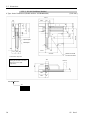
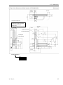
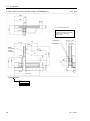
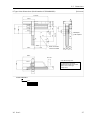
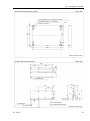
2.5 Dimensions ............................................................................................. 17
2.5.1 Single Axis .................................................................................. 17
2.5.2 Two Axis Manipulators ................................................................ 22
2.5.3 Three Axis Manipulators ............................................................. 30
2.5.4 Four Axis Manipulators ............................................................... 38
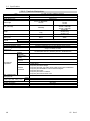
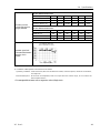
2.6 Specifications ......................................................................................... 46
2.6.1 Single Axis ..................................................................................... 46
2.6.2 Two Axis Manipulator .................................................................... 48
2.6.3 Three Axis Manipulator ................................................................. 51
2.6.4 Four Axis Manipulator ................................................................... 53
2.7 How to Set the Model ............................................................................. 55
3. Transportation, Storage, Unpacking, Handling 56
3.1 Transportation and Storage .................................................................... 56
3.2 Unpacking and Handling ........................................................................ 56
4. Installation 58
4.1 Dimensional Check for Motion Range ................................................... 61
4.2 Space Required for Maintenance........................................................... 61
4.3 Reversing Module Cable Position .......................................................... 62
4.3.1 RH, RM Module .......................................................................... 62
4.4 Mounting a Module ................................................................................. 64
4.4.1 Installation Patterns .................................................................... 68
4.5 Relations between the Stroke and the Code of the Module .................. 69
4.6 Installation of Single Axis Modules (RH, RM) ........................................ 70
4.7 Installation of Multi-axis Manipulators .................................................... 74
4.7.1 RG-HM Manipulator ................................................................... 74
4.7.2 RG-MS Manipulator .................................................................... 84
4.7.3 RD-HM Manipulator .................................................................... 94

TABLE OF CONTENTS
vi X5 Rev.1
4.7.4 RD-MS Manipulator ................................................................... 107
4.8 Installation of Additional Module ........................................................... 111
4.8.1 First Manipulator ....................................................................... 115
4.8.2 Second, Third, Forth Manipulators .......................................... 116
4.9 Mounting End Effector to Slider ............................................................ 118
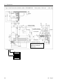
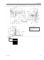
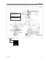
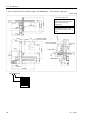
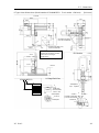
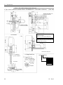
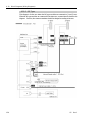
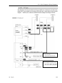
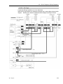
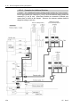
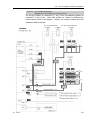
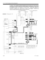
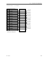
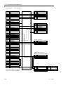
4.10 Block Diagrams (Wiring Diagrams) ....................................................... 119
4.10.1 Single Module Type ................................................................... 119
4.10.2 RG, RD Type .............................................................................. 120
4.10.3 YZ Type ...................................................................................... 121
4.10.4 RP Type ..................................................................................... 122
4.10.5 RU Type ..................................................................................... 123
4.10.6 Examples for Additional Modules .............................................. 124
4.10.7 Connector Label ........................................................................ 128
4.11 Connector Pin Assignments ................................................................... 129
4.12 Cable Connection .................................................................................. 138
4.13 Calibration .............................................................................................. 140
4.14 Adjusting Cable Support Length ............................................................ 144
4.15 Reversing Connector Box ...................................................................... 147
4.15.1 RG, RP, RU Manipulators .......................................................... 147
4.15.2 Single Axis Modules, RD Manipulators ..................................... 147
4.16 Reversing L-fixture ................................................................................. 148
4.16.1 YZ, RP-HMSz, RU Manipulators ............................................... 148
4.17 Reversing RU Module ........................................................................... 149
4.18 User Cables and Pneumatic Tubes ....................................................... 151
4.19 Brake Release Setting (RC620) ............................................................ 152
5. Maintenance and Inspection 153
5.1 Safety Precautions for Maintenance ..................................................... 154
5.2 Routine Inspections............................................................................... 156
5.2.1 Inspection of Bolts and Cables ................................................. 156
5.3 Periodic Inspections .............................................................................. 157
5.3.1 Inspection of Timing Belt (Only for RS, RSz module) ............... 157
5.4 Periodic Replacement of Expendable Parts ......................................... 160
5.4.1 Replacement of Cable ............................................................... 161
5.4.2 Replacement of Timing Belt (Only for RS, RSz module) .......... 167
5.4.3 Replacing the Lithium Battery (Battery Unit)............................. 171
5.5 Replacing the Motors ............................................................................ 175
5.5.1 Types of Motors ......................................................................... 176
5.5.2 Location of Motors ..................................................................... 176
5.5.3 Replacing the Motor on Each Module ....................................... 176
5.6 Replacing the Signal Relay Board ........................................................ 195
5.6.1 Before Replacing the Signal Relay Board ................................ 195
5.6.2 How to Replace the Signal Relay Board ................................... 196
5.7 Overhaul ................................................................................................ 197
5.8 Precautions for Disposal of Modules .................................................... 197
5.9 Maintenance Parts List ......................................................................... 198

1.1 Conventions
X5 Rev.1 1
1. Safety
Installation and transportation of Manipulators and robotic equipment shall be
performed by qualified personnel and should conform to all national and local
codes.
Please read this manual and other related manuals before installing the robot
system or before connecting cables.
Keep this manual handy for easy access at all times.
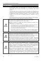
1.1 Conventions
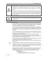
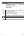
Important safety considerations are indicated throughout the manual by the
following symbols. Be sure to read the descriptions shown with each symbol.
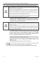
WARNING
This symbol indicates that a danger of possible serious injury
or death exists if the associated instructions are not followed
properly.
WARNING
This symbol indicates that a danger of possible harm to people
caused by electric shock exists if the associated instructions are
not followed properly.
CAUTION
This symbol indicates that a danger of possible harm to people
or physical damage to equipment and facilities exists if the
associated instructions are not followed properly.
1.2 Design and Installation Safety
Only trained personnel should design and install the robot system. Trained
personnel are defined as those who have taken robot system training and
maintenance training classes held by the manufacturer, dealer, or local
representative company, or those who understand the manuals thoroughly and
have the same knowledge and skill level as those who have completed the training
courses.
To ensure safety, a safeguard must be installed for the robot system. For details
on the safeguard, refer to the Installation and Design Precautions in the Safety
chapter of the EPSON RC+ User’s Guide.
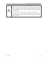
The following items are safety precautions for design personnel:
WARNING
■
Personnel who design and/or construct the robot system with this product must
read the
Safety chapter in the EPSON RC+ User’s Guide to understand the safety
requirements before designing and/or constructing the robot system.
Designing
and/or constructing the robot system without understanding the safety
requirements is extremely hazardous, may result in serious bodily injury and/or
sever
e
equipment damage to the robot system, and may cause serious safety
problems.

1.3 Operation Safety
2 X5 Rev.1
WARNING
■
The Manipulator and the Controller must be used within the environmental
conditions described in their respective manuals.
This product has been
designed and manufactured strictly for use in a normal indoor environment.
Using the product in an environmen
t that exceeds the specified environmental
conditions may not only shorten the lif
e of the product but may also cause serious
safety problems.
■
The robot system must be used within the installation requirements described in
the manuals.
Using the robot system outside of the installation requirements
may not only shorten the life cycle of the product but also cause serious safety
problems.
Further precautions for installation are mentioned in the chapter 4. Installation. Please
read this chapter carefully to understand safe installation procedures before installing the
robots and robotic equipment.
1.3 Operation Safety
The following items are safety precautions for qualified Operator personnel:
WARNING
■
Please carefully read the
Safety-related Requirements in the Safety chapter of
the
Safety and Installation manual.
Operating the robot system without
understanding the safety requirements is extremely hazardous and may result in
serious bodily injury and/
or severe equipment damage to the robot system.
■
Do not enter the operating area of the Manipulator while the power to the robot
system is turned ON.
Entering the operating area with the power ON is
extremely hazardous and may cause serious safety prob
lems as the Manipulator
may move even if it seems to be stopped.
■
Before operating the robot system, make sure that no one is inside the
safeguarded area.
The robot system can be operated in the mode for teaching
even when someone is inside the safeguarded area.
The motion of the Manipulator is always in restricted status (low speeds and low
power) to secure the safety of an operator.
However, operating the robot
system while someone is inside the safeguarded are
a is extremely hazardous
and may result in serious safety problems
in case that the Manipulator moves
unexpectedly.
■
Immediately press the Emergency Stop switch whenever the Manipulator moves
abnormally
during operation. Continuing the operation while the Manipulator
moves abnormally is extremely hazardous and may result in serious bodily injury
and/or severe equipment change to the robot system.
WARNING
■
Be sure to connect the AC power cable to a power receptacle. DO NOT connect
it directly to a
factory power source. To shut off power to the robot system, pull
out the power plug from the power source. Performing any work while
connecting the AC power cable to a factory power source is extremely hazardous
and may result in electric shock and/or m
alfunction of the robot system.

1.4 Emergency Stop
X5 Rev.1 3
WARNING
■
Before performing any repla
cement procedure, turn OFF the Controller and
related equipment, and then pull out the power plug from the power source.
Performing any replacement procedure with the power ON is
extremely
hazardous and may result in electric shock and/or malfunction of the robot
system.
■
Do not
insert or pull out the motor connectors while the power to the robot system
is turned ON.
Inserting or pulling out the motor connectors with the power ON is
extremely hazardous and may result in serious bodily injury as the Manipulator
may move abnormally, and also may result in electric shock and/or malfunction of
the robot system.
CAUTION
■
D
o not apply any excessive force to the module and
peripheral equipment.
Applying excessive force to the module and peripheral equipment may result in
damage to them.
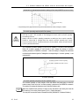
1.4 Emergency Stop
If the Manipulator moves abnormally during operation, immediately press the Emergency
Stop switch. Pressing the Emergency Stop switch immediately changes the manipulator
to deceleration motion and stops it at the maximum deceleration speed.
However, avoid pressing the Emergency Stop switch unnecessarily while the Manipulator
is running normally. Otherwise, the Manipulator may hit the peripheral equipment since
the operating trajectory until the robot system stops is different from that in normal
operation.
Do not press the Emergency Stop switch unnecessarily while the Manipulator is operating.
Pressing the switch during operation makes the brakes work. This will shorten the life of
the brakes due to the worn friction plates.
Normal brake life cycle: About 2 years (when the brakes are used 100 times/day)
Also, the Emergency Stop during operation applies impact on the reduction gear unit, and
it may result in the short life of the reduction gear unit.
To place the robot system in emergency mode during normal operation, press the
Emergency Stop switch while the Manipulator is not moving.
Refer to the Robot Controller manual for instructions on how to wire the Emergency Stop
switch circuit.
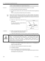
When the Manipulator is stopped by the emergency stop function (the electric current for
the motor is cut off), the J1 and J2 axes may overrun a maximum of 150 mm from their
servo motion target points. Therefore, design the layout of the robot system so that the
end effector does not collide with peripheral equipment.
When the Manipulator is stopped by the emergency stop while it is moving with large load
being applied, an error may occur. If the error occurs, reset it by the Reset command.
Example: If the Emergency Stop switch is pressed while the RH module is carrying
an 80 kg workpiece.
The following error occurs:
5040: Motor torque output failure in high power state.
NOTE

1.4 Emergency Stop
4 X5 Rev.1
Do not turn OFF the Controller while the Manipulator is operating.
If you attempt to stop the Manipulator in emergency situations such as “Safeguard Open”,
make sure to stop the Manipulator using the Emergency Stop switch of the Controller.
If the Manipulator is stopped by turning OFF the Controller while it is operating, the
following problems may occur.
Reduction of the life and damage of the reduction gear unit
Position gap at the joints
In addition, if the Controller was forced to be turned OFF by blackouts and the like while
the Manipulator is operating, make sure to check the following points after power
restoration.
Whether or not the reduction gear is damaged
Whether or not the joints are in their proper positions
If there is a position gap, perform calibration by referring to the 4.13. Calibration in this
manual.
Before using the Emergency Stop switch, be aware of the followings.
- The Emergency Stop (E-STOP) switch should be used to stop the Manipulator only
in case of emergencies.
- To stop the Manipulator operating the program except in emergency, use Pause (halt)
or STOP (program stop) commands.
Pause and STOP commands do not turn OFF the motors. Therefore, the brake does
not function.
- For the Safeguard system, do not use the circuit for E-STOP.
For details of the Safeguard system, refer to the following manuals.
EPSON RC+ User’s Guide 2. Safety - Installation and Design Precautions
- Safeguard System
Safety and Installation 2.6 Connection to EMERGENCY Connector
To check brake problems, refer to the following manuals.
Safety and Installation 5.1.1 Manipulator
- Inspection While the Power is ON (Manipulator is operating)

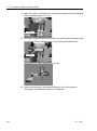
1.5 Moving sliders by hand in emergency mode
X5 Rev.1 5
1.5 Moving sliders by hand in emergency mode
When the system is placed in emergency mode, move the modules by hand as follows:
RH module ......... Push the slider by hand.
RM module ........ Push the slider by hand.
RSz module ....... The axis cannot be moved up/down by hand because the
electromagnetic brake is applied to the axis. Move the axis
up/down while pushing the Z axis brake release switch.
RU module ......... Rotate the end effector or flange by hand.
CAUTION
■
Be careful not to allow the
Z axis and end effector to move down by their own
weight while pressing the Z axis brake release switch.
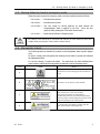
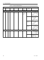
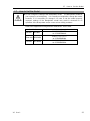
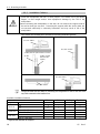
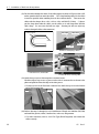
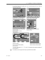
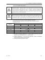
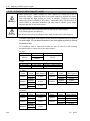
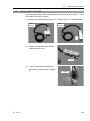
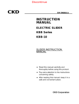
1.6 Manipulator Labels
The following labels are attached at locations on the Manipulator where specific dangers
exist.
Be sure to comply with descriptions and warnings on the labels to operate and maintain
the Manipulator safely.
Do not tear, damage, or remove the labels. Use meticulous care when handling those
parts or units to which the following labels are attached as well as the nearby areas:
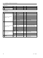
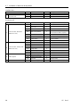
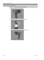
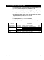
Location Label NOTE
A
Do not touch current-carrying part to avoid electric
shock.
B
This label is on the top face of the module.
C
Only authorized personnel should perform sling
work and operate a crane and a forklift.
When these operations are performed by
unauthorized personnel, it is extremely hazardous
and may result in serious bodily injury and/or severe
equipment damage to the robot system.
D
Be careful of the hand falling / rotation while the
brake release button is being pressed.

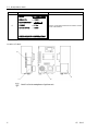
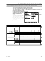
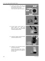
1.6 Manipulator Labels
6 X5 Rev.1
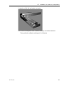
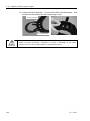
Location Label NOTE
E
MODEL
:R114X5H040
SERIAL NO. :00001
MANUFACTURED :10/2016
WEIGHT :21kg
MOTOR POWER
:400W
SEIKO EPSON CORPORATION
Refer to 4.5 Relations between the Stroke and the
Code of the Module.
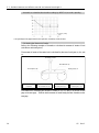
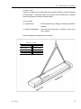
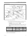
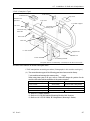
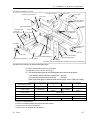
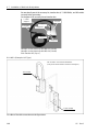
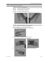
Location of Labels
C
D
A
E
Label D is for the manipulator of up/down axis.
NOTE

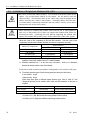
2.1 Features of EZ Modules
X5 Rev.1 7
2. Model Numbers and Specifications
2.1 Features of EZ Modules
The features of EZ modules are as follows:
(1) A wide range of module stroke lengths and various module combinations
- EZ modules provide a wide range of module stroke lengths. (RH, RM, RSz, and
RU)
- Due to this wide range of module stroke lengths, the module combinations variety:
single-axis modules, multi-axis manipulators, two-axis XY manipulators, and
two-axis YZ manipulator.
(2) Controllability of two or more manipulators by one controller
- When the additional module is installed (a two-axis manipulator is installed to a
two-axis manipulator, a single-axis module is installed to a three-axis manipulator,
etc.), the RC700-A robot controller can control multiple manipulators by unified
managing of the point data.
- With the Multi-Manipulator feature, the RC700-A robot controller can control up to
16 single-axis modules separately. (Control unit: 8, Drive unit1: 4 + Drive unit2: 4
+ Drive unit3: 4) However, there is a limit to the maximum capacity. Please
contact us for the details.
(3) Available for Large-load
- EZ modules are available for large-load.
Max. Payload: from 80 kg (Single-axis) to 10 kg (four-axis)
The capacity for large-load has been improved by enhanced allowable moment of
inertia of Axis 4.
- Optimal control for load makes the handling in large-load stable.
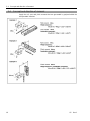
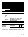
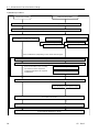
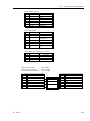
Constituent module
Model
*1
Constituent module
*2
RH
module
RM
module
RSz
module
RU
module
Single axis
RH
–
–
–
RM
–
–
–
Two axis
XY
RG-HM
–
–
YZ
YZ-MS
–
–
Three axis
XYZ
RP-HMSz
–
Four axis
XYZU
RU-HMSz
Additional Modules
Model
*1
Constituent module
*2
RH
module
RM
module
RSz
module
RU
module
Single axis
RH
–
–
–
RM
–
–
–
Two axis
XY
RG-HM
–
–
–

2.2 Model Numbers
8 X5 Rev.1
*1: For the figures of respective models, refer to 2.2 Model Numbers.
*2: Outline of each module
RH module : Large payload
RM module : Medium payload
RSz module : For vertical axis (Z axis)
RU module : For rotation axis (U axis)
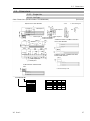
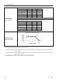
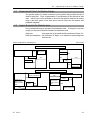
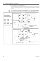
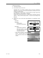
2.2 Model Numbers
Example 1: RP-HMSz
(RH: 600 mm stroke, RM: 500 mm stroke, RSz: 300 mm stroke, Mount direction type: A)
X5 P 6H 5M 3S 0 A
Mount direction type: C
Additional module: Exists
Axis 3: None
Axis 2: 750 mm stroke and RM module
Axis 1: 800 mm stroke and RH module
Combination type: RG
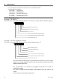
Example 2: RG-HM (Additional module)
(RH: 800 mm stroke, RM: 750 mm stroke, Mount direction type: C)
X5 G 8H 7M 00 A C
Mount direction type: C
Additional module: Exists
Axis 3: None
Axis 2: 750 mm stroke and RM module
Axis 1: 800 mm stroke and RH module
Combination type: RG
The second digit from the right in the model number means that Axis 4 (RU module)
exists or not. For the additional module, the second digit from the right means that the
additional module exists or not.
The “model number” is the number for an aggregate of parts that are necessary for
manipulator assembly.
The “code” in Chapter 4 and later chapters is the number for each part, parts set, and
module.
Do not confuse the model number and the code.

2.2 Model Numbers
X5 Rev.1 9
Model numbers shown in the software
Combination
Model Number & Model Number shown in the software
Two axis RG-HM
X5G
ex.: X5G8H7M000C
Three axis RP-HMSz
X5P
ex.: X5P6H5M3S0A
Four axis RU-HMSz
X5UHMS
ex.: X5U6H5M3S1A
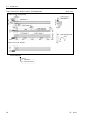
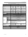
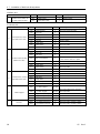
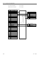
2.2.1 Single Axis
Single Axis (RH, RM)
Item Combination Axis 1 Axis 2 Axis 3
Axis 4
(Additional
module)
Mount
Direction
X5
S
0H
00
00
0
A
X5 S: Single Axis 6H : RH600
8H : RH800
0H : RH1000
00: none 00: none
0: none
A: Additional
module
A: Standard
S: Single Axis 0L : RH2000 00: none 00: none
0: none
A: Additional
module
A: Standard
B: Left side
mount
S: Single Axis 3M : RM350
5M : RM550
00: none 00: none
0: none
A: Additional
module
A: Standard

2.2 Model Numbers
10 X5 Rev.1
2.2.2 Two Axis Manipulators
Two Axis Manipulators (RG-HM, YZ-MS)
Item Combination
Axis 1 Axis 2 Axis 3
Axis 4
(Additional
module)
Mount
Direction
X5
G
8H
7M
00
0
C
X5 G: RG -HM
8H: RH800 5M: RM550
7M: RM750
00: none 0: none
A: Additional
module
A: standard
X5G*H*M000A
B: Y mirrored
X5G*H*M000B
C: Y slider
mirrored
X5G*H*M000
C
D: Slider
mirrored
X5G*H*M000D
X5
Z
00
7M
2S
0
A
X5 Z: YZ -MS
00: none 7M: RM750 2S: RSz200 0: none A: standard
X5Z00*M*S0A
B: Y mirrored
X5Z00*M*S0B

2.2 Model Numbers
X5 Rev.1 11
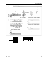
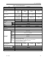
2.2.3 Three Axis Manipulators
Three Axis Manipulators (RP-HMSz)
Item
Combination Axis 1 Axis 2 Axis 3 Axis 4
Mount
Direction
X5
P
6H
5M
3S
0
A
X5 P: RP
-HMSz
4H: RH400
6H: RH600
8H: RH800
3M: RM350
5M: RM550
2S: RSz200
3S: RSz300
0: none A: standard
X5P*H*M*S0A
B:
Y mirrored
X5P*H*M*S0B
C:
YZ mirrored
X5P*H*M
*S0C
D:
Z mirrored
X5P*H*M*S0D
2.2.4 Four Axis Manipulators
Four Axis Manipulators (RU-HMSz)
Item
Combination Axis 1 Axis 2 Axis 3
Axis 4
(RU module)
Mount
Direction
X5
U
6H
5M
3S
1
A
X5 U: RU
-HMSz
4H: RH400
6H: RH600
8H: RH800
3M: RM350
5M: RM550
2S: RSz200
3S: RSz300
1: RU module A:
standard
X5U*H*M*S1A
B:
Y mirrored
X5U*H*M*S1B
C:
YZ
mirrored
X5U*H*M*S1C
D:
Z mirrored
X5U*H*M*S1D

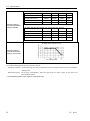
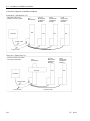
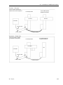
2.3 Relation between end effector mass W and moment arm length L
12 X5 Rev.1
2.3 Relation between end effector mass W and moment arm length L
CAUTION
■
The total weight of the end effector and the work piece must be
within the
specified
values for each Manipulator.
Always set the weight parameters according to the load. Setting a value that is
smaller than the actual load may cause errors, excessive shock, insufficient
function of the Manipulator, and/or shorten the life cycle of parts/m
echanisms.
■
The
moment of inertia of the load (weight of the end effector and work piece)
must be
set within the specified values for each module.
■
The
eccentric quantity of the load (weight of the end effector and work piece)
must be
set within the specified values for each module.
Moment of Inertia and the INERTIA Setting
The moment of inertia is defined as “the ratio of the torque applied to a rigid body and its
resistance to motion”. Set INERTIA parameter considering the weight of the end effector
and work piece attached to the RU rotation center.
CAUTION
■
The
moment of inertia of load (weight of the end effector and work piece) must be
0.12
kgm
2
or less. RU module is not designed to work with moment of inertia
exceeding
0.12 kgm
2
.
Al
ways set the moment of inertia (INERTIA) parameter according to the moment
of inertia. Setting a value that is smaller than the actual moment of inertia may
cause errors, excessive shock, insufficient function of the module, and/or shorten
the life cycle
of parts/mechanisms.
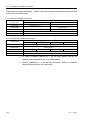
The acceptable moment of inertia of load for RU module is 0.04 kgm
2
at the rating and
0.12 kgm
2
at the maximum. When the moment of inertia of load exceeds the rating,
change the setting of moment of inertia (INERTIA) parameter of load of INERTIA
command. After the setting is changed, the maximum acceleration/deceleration speed of
Axis 4 is corresponding to “moment of inertia” is set automatically.
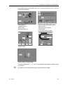
Moment of inertia of load on the RU rotation center
The moment of inertia of load (weight of the end effector and work piece) on the RU
rotation center can be set by the “moment of inertia (INERTIA)” parameter of the
INERTIA command.
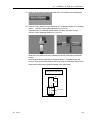
The method for setting the parameter varies with the software used.
EPSON
RC+
Enter the combined total moment of inertia of the end effector and work piece into the
[
Eccentricity:] box on the [Inertia] panel ([Tool] - [Robot Manager]).
You may also execute the
Inertia command from the [EPSON RC+ Monitor Window].
Page is loading ...
Page is loading ...
Page is loading ...
Page is loading ...
Page is loading ...
Page is loading ...
Page is loading ...
Page is loading ...
Page is loading ...
Page is loading ...
Page is loading ...
Page is loading ...
Page is loading ...
Page is loading ...
Page is loading ...
Page is loading ...
Page is loading ...
Page is loading ...
Page is loading ...
Page is loading ...
Page is loading ...
Page is loading ...
Page is loading ...
Page is loading ...
Page is loading ...
Page is loading ...
Page is loading ...
Page is loading ...
Page is loading ...
Page is loading ...
Page is loading ...
Page is loading ...
Page is loading ...
Page is loading ...
Page is loading ...
Page is loading ...
Page is loading ...
Page is loading ...
Page is loading ...
Page is loading ...
Page is loading ...
Page is loading ...
Page is loading ...
Page is loading ...
Page is loading ...
Page is loading ...
Page is loading ...
Page is loading ...
Page is loading ...
Page is loading ...
Page is loading ...
Page is loading ...
Page is loading ...
Page is loading ...
Page is loading ...
Page is loading ...
Page is loading ...
Page is loading ...
Page is loading ...
Page is loading ...
Page is loading ...
Page is loading ...
Page is loading ...
Page is loading ...
Page is loading ...
Page is loading ...
Page is loading ...
Page is loading ...
Page is loading ...
Page is loading ...
Page is loading ...
Page is loading ...
Page is loading ...
Page is loading ...
Page is loading ...
Page is loading ...
Page is loading ...
Page is loading ...
Page is loading ...
Page is loading ...
Page is loading ...
Page is loading ...
Page is loading ...
Page is loading ...
Page is loading ...
Page is loading ...
Page is loading ...
Page is loading ...
Page is loading ...
Page is loading ...
Page is loading ...
Page is loading ...
Page is loading ...
Page is loading ...
Page is loading ...
Page is loading ...
Page is loading ...
Page is loading ...
Page is loading ...
Page is loading ...
Page is loading ...
Page is loading ...
Page is loading ...
Page is loading ...
Page is loading ...
Page is loading ...
Page is loading ...
Page is loading ...
Page is loading ...
Page is loading ...
Page is loading ...
Page is loading ...
Page is loading ...
Page is loading ...
Page is loading ...
Page is loading ...
Page is loading ...
Page is loading ...
Page is loading ...
Page is loading ...
Page is loading ...
Page is loading ...
Page is loading ...
Page is loading ...
Page is loading ...
Page is loading ...
Page is loading ...
Page is loading ...
Page is loading ...
Page is loading ...
Page is loading ...
Page is loading ...
Page is loading ...
Page is loading ...
Page is loading ...
Page is loading ...
Page is loading ...
Page is loading ...
Page is loading ...
Page is loading ...
Page is loading ...
Page is loading ...
Page is loading ...
Page is loading ...
Page is loading ...
Page is loading ...
Page is loading ...
Page is loading ...
Page is loading ...
Page is loading ...
Page is loading ...
Page is loading ...
Page is loading ...
Page is loading ...
Page is loading ...
Page is loading ...
Page is loading ...
Page is loading ...
Page is loading ...
Page is loading ...
Page is loading ...
Page is loading ...
Page is loading ...
Page is loading ...
Page is loading ...
Page is loading ...
Page is loading ...
Page is loading ...
Page is loading ...
Page is loading ...
Page is loading ...
Page is loading ...
Page is loading ...
Page is loading ...
Page is loading ...
Page is loading ...
Page is loading ...
Page is loading ...
Page is loading ...
Page is loading ...
Page is loading ...
Page is loading ...
Page is loading ...
Page is loading ...
Page is loading ...
Page is loading ...
-
 1
1
-
 2
2
-
 3
3
-
 4
4
-
 5
5
-
 6
6
-
 7
7
-
 8
8
-
 9
9
-
 10
10
-
 11
11
-
 12
12
-
 13
13
-
 14
14
-
 15
15
-
 16
16
-
 17
17
-
 18
18
-
 19
19
-
 20
20
-
 21
21
-
 22
22
-
 23
23
-
 24
24
-
 25
25
-
 26
26
-
 27
27
-
 28
28
-
 29
29
-
 30
30
-
 31
31
-
 32
32
-
 33
33
-
 34
34
-
 35
35
-
 36
36
-
 37
37
-
 38
38
-
 39
39
-
 40
40
-
 41
41
-
 42
42
-
 43
43
-
 44
44
-
 45
45
-
 46
46
-
 47
47
-
 48
48
-
 49
49
-
 50
50
-
 51
51
-
 52
52
-
 53
53
-
 54
54
-
 55
55
-
 56
56
-
 57
57
-
 58
58
-
 59
59
-
 60
60
-
 61
61
-
 62
62
-
 63
63
-
 64
64
-
 65
65
-
 66
66
-
 67
67
-
 68
68
-
 69
69
-
 70
70
-
 71
71
-
 72
72
-
 73
73
-
 74
74
-
 75
75
-
 76
76
-
 77
77
-
 78
78
-
 79
79
-
 80
80
-
 81
81
-
 82
82
-
 83
83
-
 84
84
-
 85
85
-
 86
86
-
 87
87
-
 88
88
-
 89
89
-
 90
90
-
 91
91
-
 92
92
-
 93
93
-
 94
94
-
 95
95
-
 96
96
-
 97
97
-
 98
98
-
 99
99
-
 100
100
-
 101
101
-
 102
102
-
 103
103
-
 104
104
-
 105
105
-
 106
106
-
 107
107
-
 108
108
-
 109
109
-
 110
110
-
 111
111
-
 112
112
-
 113
113
-
 114
114
-
 115
115
-
 116
116
-
 117
117
-
 118
118
-
 119
119
-
 120
120
-
 121
121
-
 122
122
-
 123
123
-
 124
124
-
 125
125
-
 126
126
-
 127
127
-
 128
128
-
 129
129
-
 130
130
-
 131
131
-
 132
132
-
 133
133
-
 134
134
-
 135
135
-
 136
136
-
 137
137
-
 138
138
-
 139
139
-
 140
140
-
 141
141
-
 142
142
-
 143
143
-
 144
144
-
 145
145
-
 146
146
-
 147
147
-
 148
148
-
 149
149
-
 150
150
-
 151
151
-
 152
152
-
 153
153
-
 154
154
-
 155
155
-
 156
156
-
 157
157
-
 158
158
-
 159
159
-
 160
160
-
 161
161
-
 162
162
-
 163
163
-
 164
164
-
 165
165
-
 166
166
-
 167
167
-
 168
168
-
 169
169
-
 170
170
-
 171
171
-
 172
172
-
 173
173
-
 174
174
-
 175
175
-
 176
176
-
 177
177
-
 178
178
-
 179
179
-
 180
180
-
 181
181
-
 182
182
-
 183
183
-
 184
184
-
 185
185
-
 186
186
-
 187
187
-
 188
188
-
 189
189
-
 190
190
-
 191
191
-
 192
192
-
 193
193
-
 194
194
-
 195
195
-
 196
196
-
 197
197
-
 198
198
-
 199
199
-
 200
200
-
 201
201
-
 202
202
-
 203
203
-
 204
204
-
 205
205
-
 206
206


Epson EZ Modules 1-Axis Robots User manual
- Category
- Robotics
- Type
- User manual
- This manual is also suitable for
Ask a question and I''ll find the answer in the document
Finding information in a document is now easier with AI
Related papers
-
Epson EZ Modules 3-Axis Robots User manual
-
Epson C12XL 6-Axis Robots Maintenance Manual
-
-
Epson GX4 SCARA Robots User manual
-
Epson GX4B SCARA Robots User manual
-
-
-
-
-
Other documents
-
Hasbro 81139 User manual
-
Yamaha Robotics YK120X User manual
-
Panduit PA24849A01 User manual
-
 CAYMON CASY 028/B Installation guide
-
 CKD KBX-30(Side mounted motor axis) User manual
-
BEA PNEUMATIC PUSH BUTTONS User guide
-
 CKD KBX-50(Side mounted motor axis) User manual
-
 CKD KBB-10 Series User manual
-
 Mount Plus 4330178939 User guide
-
adept technology 300CR User manual


