Page is loading ...

P/N 5500308-20 (Rev B)
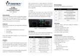
Perle 10/100/1000 Ethernet
Media Converter
Module
Installation Guide
C-1110-XXXXX Unmanaged Module
CM-1110-XXXXX Managed Module
C-1110-SFP Unmanaged Module
CM-1110-SFP Managed Module

Perle 10/100/1000 Media Converter Module – Installation Guide
2
Overview
This document contains instructions necessary for the
installation and operation of the Perle 10/100/1000
Media Converter Module(s) (C-1110 and CM-1110) to
be used in conjunction with a Perle MCR chassis. The
C-1110’s are unmanaged media converter modules,
and the CM-1110’s are the managed versions. These
products convert a 10/100/1000Base-T cable
connection (copper) to a 1000Base-X connection
(fiber). The fiber connection can be either single mode
(SM) or multimode (MM) and can operate over different
wavelengths and distances, depending on the model
selected (see table below).
Model
Connector
(xx)
Mode - Distance Wavelength
C-1110-M2xx05
CM-1110-M2xx05
SC/ST/LC MM - 550 m/1804 ft. 850/850 nm
C-1110-M1SC05U
CM-1110-M1SC05U
SC
MM - 550 m/1804 ft
1310/1550
C-1110-M1SC05D
CM-1000-M1SC05D
SC
MM - 550 m/1804 ft
1550/1310
C-1110-M2xx2
CM-1110-M2xx2
SC/ST/LC MM - 2 km/1.2 mi. 1310/1310 nm
C-1110-S2xx10
CM-1110-S2xx10
SC/ST/LC SM - 10 km/6.2 mi. 1310/1310 nm
C-1110-S1SC10U
CM-1110-S1SC10U
SC SM - 10 km/6.2 mi. 1310/1490 nm
C-1110-S1SC10D
CM-1110-S1SC10D
SC SM - 10 km/6.2 mi. 1490/1310 nm
C-1110-S1SC20U
CM-1110-S1SC20U
SC SM - 20 km/12.4 mi. 1310/1490 nm
C-1110-S1SC20D
CM-1110-S1SC10D
SC SM - 20 km/12.4 mi. 1490/1310 nm
C-1110-S2xx40
CM-1110-S2xx40
SC/ST/LC SM - 40 km/25 mi. 1310/1310 nm

Perle 10/100/1000 Media Converter Module – Installation Guide
3
C-1110-S1SC40U
CM-1110-S1SC40U
SC SM - 40 km/25 mi. 1310/1490 nm
C-1110-S1SC40D
CM-1110-S1SC40D
SC SM - 40 km/25 mi. 1490/1310 nm
C-1110-S2xx70
CM-1110-S2xx70
SC/ST/LC SM - 70 km/43.5 mi. 1550/1550 nm
C-1110-S1SC80U
CM-1110-S1SC80U
SC SM - 80 km/50 mi. 1510/1590 nm
C-1110-S1SC80D
CM-1110-S1SC80D
SC SM - 80 km/50 mi. 1590/1510 nm
C-1110-S2xx120
CM-1110-S2xx120
SC/ST/LC SM - 120 km/75 mi. 1550/1550 nm
C-1110-S1SC120U
CM-1110-S1SC120U
SC SM – 120 km/75 mi. 1510/1590 nm
C-1110-S1SC120D
CM-1110-S1SC120D
SC SM - 120 km/75 mi. 1590/1510 nm
C-1110-S2xx160
CM-1110-S2xx160
SC/ST/LC SM - 160 km/100 mi. 1550/1550 nm
C-1110-SFP
CM-1110-SFP
SFP
Note 1
Note 1: Fiber characteristics will vary by SFP Fiber
module.
Refer the Perle web site for the most up to date
Installation guides, models and specifications.
http://www.perle.com/

Perle 10/100/1000 Media Converter Module – Installation Guide
4
Installation
The module comes equipped with a bank of DIP
switches and jumpers for setting configuration. The
default dip switch settings (all switches UP) and default
jumper settings will work for most installations. For
information on the management options of the CM-
1110 module, refer to the MCR-MGT Module User’s
Guide.
The following steps are used to configure the Perle
10/100/1000 Ethernet Media Converter Module:
1. Insert SFP Module. (SFP Models only)
2. Set the Auto-MDIX jumper setting. (Optional).
3. Set the Auto-Config jumper. (CM-1110 only)
(optional)
4. Set the DIP switch settings (optional).
5. Set the SGMII Interface support (if your SFP has a
SGMII Interface).
6. Insert the Media Converter Module into the chassis.
7. Connect the copper cable.
8. Connect the fiber cable.
Auto-MDIX Jumper
Note: The factory settings for Auto-MDIX will work for
most installations, but if a settings change is needed,
follow the procedure below.
The AUTO-MDIX jumper (J6) is located on the upper
edge, at the midpoint of the module (see diagram
below for labelling). By covering or strapping pins 2 and
3(AUTO), the C-1110 and CM-1110 will automatically
detect the Ethernet cable’s polarity and configure itself
as either an MDI or an MDIX device. By covering or

Perle 10/100/1000 Media Converter Module – Installation Guide
5
strapping pins 1 and 2(MDIX), the C-1110 and CM-
1110 will operate as an MDIX device
Removing the strapping is the same as AUTO.
Note: The default jumper setting is AUTO
Auto-Config Jumper (CM-1110 only)
The Auto-Config jumper (J5) is located just above the
Auto-MDIX jumper (see above). Refer to the diagram
below for labelling. This jumper only applies to CM-
1110 modules.
Strapping pins 1 and 2 of the jumper will set the
module in SW mode and strapping pins 2 and 3 will set
it in Auto Config mode.
Auto: When set to Auto the module will, at power-up,
check its internal flash memory to see if configuration
information has been downloaded to it from a
management module. If so, it will use this as its running
configuration. If there is no configuration in flash it will
read the settings of the DIP switches and use those as
its running configuration.
SW: When set to SW (Switch), the module will, at
power-up, read the settings of the DIP Switches and
use those as its running configuration. It will ignore any
configuration information in its flash memory.
Note: The default jumper setting is Auto

Perle 10/100/1000 Media Converter Module – Installation Guide
6
Using SFP’s with SGMII Interfaces
This media converter module is able to operate with
SFP’s that utilize an SGMII interface. This feature is
enabled on the unmanaged modules through the
hardware strapping listed below. For the managed
models, it is enabled through the software
management interface. (See details below).
C Model: (Hardware only)*
To set SGMII Interface support on a C-1110 module,
strap pins 1 and 2 on jumper J5 (see diagram below)*.
CM Model: (Software only)*
Using the MCR-MGT Web Manager, select the SGMII
Interface checkbox under fiber port settings to enable
support for that CM-1110 module.
*SFP’s with SGMII interface are supported on certain C-1110-SFP
and CM-1110-SFP modules. The last 5 digits of the serial number
on these modules must begin with the number 17 or greater.

Perle 10/100/1000 Media Converter Module – Installation Guide
7
Dip Switches
Auto Negotiation copper (Switch 1)
Switch
Position
Mode
Up (default) Auto
Down Off
Note: Auto negotiation should only be turned off, if the copper link
partner does not support Auto Negotiation and fixed settings are
required by the copper link partner.
Auto: When enabled, the Media Converter Module will
negotiate with its link partner to determine the most
optimal parameters for this connection. The C-1110
and CM-1110 will advertise capabilities of 10,100 and
1000 Mbps, full and half duplex as well as pause, and
remote fault capabilities to the link partner.
If the copper link partner does not support Auto
negotiation, the C-1110 and CM-1110 will parallel
detect to 10 or 100 Mbps and force Half Duplex mode
as per IEEE specifications.
Off: When the Auto Negotiation switch is set to the
OFF position, the Media Converter Module will not

Perle 10/100/1000 Media Converter Module – Installation Guide
8
negotiate the Ethernet parameters with the copper link
partner. The parameters used by the Media Converter
Module will be determined by the Duplex (switch 4) and
Speed (switch 5) DIP switch settings.
Link Mode (Switch 2)
Switch
Position
Mode
Up (default) Smart Link Pass-Through Mode
Down Standard Mode
Smart Link Pass-Through: In this mode, the link state
on one connection is directly reflected through the
Media Converter Module to the other connection. If link
is lost on one of the connections, then the other link will
be brought down by the Media Converter Module.
With Media Converters on both ends of the fiber link
and both setup for Link Pass-Through, a loss of copper
link on the far end device will propagate through both
Converters and will result in a loss of copper link at the
near end device. This would, in effect, resemble a
direct copper connection.
Standard Mode: In this mode, the links on the fiber
and copper sides can be brought up and down
independently of each other. A loss of link on either the
fiber or copper port can occur without affecting the
other connection.
Fiber Fault Alert (Switch 3)
Switch
Position
Mode
Up (default) Enabled
Down Disabled

Perle 10/100/1000 Media Converter Module – Installation Guide
9
Enabled: If the Media Converter Module detects a loss
of signal on the fiber receiver, it will immediately
disable its fiber transmitter signal. This, in effect,
notifies the fiber link partner that an error condition
exists on the fiber connection.
If the remote Media Converter is set up for Fiber Fault
Alert (FFA) and the local Media Converter is set up with
Link Pass-Through, a loss of fiber link on either the
transmit or receive line will be passed through to the
local copper connection thus notifying the connected
device.
If the Media Converter has been set to Smart Link
Pass-Through mode, the effect will be the same as
FFA, since the link loss on the fiber receiver will result
in bringing down the copper link, which will in turn
cause the transmit fiber link to be brought down.
Note: This feature only takes effect if Fiber Negotiation
has been turned off.
Disabled: The Media Converter Module will not
monitor for or generate Fiber Fault Alert.
The following diagram is an illustration of the operation
of this feature.
(A) – Remote Media Converter setup for Fiber Fault
Alert Enabled, Fiber Negotiation – OFF and Link Mode
– Standard.
(B) – Local Media Converter setup for Fiber Fault Alert
-Enabled, Smart Link Pass-Through - Enabled and
Fiber Negotiation - OFF

Perle 10/100/1000 Media Converter Module – Installation Guide
10
(A) Loses fiber connection on its receiver.
(A) Disables fiber transmitter.
(B) Detects loss of link on its fiber receiver.
(B) Drops link on copper connection because Smart
Link Pass-Through is configured.
(A) Link on copper connection is not affected because
Smart Link Mode is set to Standard.
Duplex copper (Switch 4)
Switch
Position
Mode
Up (default) Full
Down Half
Note: When Auto Negotiation (SW1) is set to Off, the
Media Converter will use this Duplex setting for its
copper connection.
Up: The Media Converter Module will be set to Full
Duplex mode.
Down: The Media Converter Module will be set to Half
Duplex mode.
Speed copper (Switch 5)
Switch
Position
Mode
Up (default) 100
Down 10
Note When Auto Negotiation (SW1) is set to Off, the
Media Converter Module will use this switch setting for
its Ethernet copper speed setting.
Up: The Media Converter will be fixed at 100 Mbps.

Perle 10/100/1000 Media Converter Module – Installation Guide
11
Down: The Media Converter will be fixed at 10 Mbps.
Fiber Negotiation (Switch 6)
Switch
Position
Mode
Up (default) Auto
Down Off
Up: The Media Converter will negotiate Ethernet
parameters on the fiber connection. This will ensure
that the most optimal connection parameters will be in
effect. If connecting to another Perle Media Converter,
this parameter should be set to Auto. The Media
Converter Module will advertise 1000Mbps, Full and
Half Duplex, no Pause.
Down: The Media Converter Module’s fiber will be
fixed to 1000Mbps, Full Duplex.
When using a 100 Mbit SFP module
Full/Half Duplex on Fiber (Switch 6)
Switch
Position
Mode
Up (default) Full
Down Half
Up: The Media Converter Module will be set to Full
Duplex mode on its fiber link.
Down: The Media Converter Module will be set to Half
Duplex mode on its fiber link.
Loopback (Switch 7)
Switch
Position
Mode
Up (default) Disabled

Perle 10/100/1000 Media Converter Module – Installation Guide
12
Down Enabled
Disabled: This is the setting for normal operation. The
switch must be set to this position in order for data to
pass through the Media Converter Module.
Enabled: This is a test mode. All data received on the
receive (RX) fiber connection is looped back to the
transmit (TX) fiber connection. The state of the copper
link is not relevant since no data is passed through to
the copper side. This mode will override all other switch
settings.
Installing or Replacing Media
Converter Modules
Caution: Observe electrostatic discharge precautions
when installing the Media Converter Module(s) into the
Chassis. Failure to observe this caution could result in
damage to the Media Converter Module(s) and /or
chassis.
The Perle Media Converter Modules can be installed in
any available slot and in any order within the chassis.
1. Remove the Media Converter Module from its
packaging.
2. Using a cross-head screwdriver, remove the screw
holding the face plate to the Chassis to reveal the
slot opening.
3. Set the jumpers and DIP switches on the Media
Converter Module to the desired operating mode.
4. Locate the top and bottom alignment guides inside
the Chassis.
5. Using the module alignment guides gently slide the
module into the slot until it becomes flush with the

Perle 10/100/1000 Media Converter Module – Installation Guide
13
front of the Chassis. Light pressure may be needed
to seat the module. Do not force the module as you
might cause some damage. If there is resistance,
remove the module, check the module connector for
damaged or incorrectly aligned pins, if there is no
damage, retry to insert the module.
6. Tighten the captive retainer screw to ensure the
Media Converter Module is locked in place.
7. Remove the dust cap from the fiber connector and
connect the fiber and copper cables.
Removing Media Converter Modules
• Loosen the captive retainer screw on the front of
the Media Converter Module and gently pull the
Media Converter Module out.
• If not inserting a replacement, cover the opening
slot with a face plate and secure the screw.
Installing the SFP Fiber Module
• C-1110-SFP and CM-1110-SFP require an SFP
fiber module. Locate appropriate fiber module
and insert into opening.

Perle 10/100/1000 Media Converter Module – Installation Guide
14
• Ensure the SFP module is properly seated.
• SFP module may be inserted before or after the
Media Converter module is inserted into the
chassis.
• Proceed with cable connections.
Installing the Duplex Fiber Cable
• Locate a 1000Base-X compliant duplex (2
strands) fiber cable with appropriate connectors.
• Connect the fiber cables from the Media
Converter to the other Media
Converter/switch/fiber device ensuring that the
RX and TX are reversed (crossed) at the
opposite end.
Installing the Simplex Fiber Cable
• Locate a 1000Base-X compliant simplex (1-
strand) fiber cable with appropriate connectors.
• Connect the fiber cable from the Media
Converter Module to the other Media
Converter/switch/fiber device.

Perle 10/100/1000 Media Converter Module – Installation Guide
15
Installing the Copper Cable
• Locate 10/100/1000Base-T compliant copper
cables with male, RJ-45 connectors installed at
both ends.
• Connect the RJ-45 cable between the Perle
Media Converter Module and the device.
Note: The Perle Media Converter Module supports
Auto-MDIX which allows a straight-through or cross-
over Ethernet cable. See page 4 in this guide for
jumper positions.

Perle 10/100/1000 Media Converter Module – Installation Guide
16
Operation
Status LED
The C(M)-1110 Module has six status LEDs located on
the faceplate of the module.
PWR
On – Power is on; module is
operating normally
Blinking (slow) – The module is in
Loopback mode.
Blinking (fast) – The module has a
hardware failure.
FDF (fiber)
On – Full Duplex Mode.
Off – Half Duplex Mode.
LKF (fiber )
On – Fiber link is present.
Off – No fiber link present.
Blinking (slow) – Copper link down
but fiber link appears functional.
Blinking (fast) – Fiber link is up
and receiving data.
100/1000 (copper speed)
Green – 1000 Mbps
Yellow – 100 Mbps.
Off – 10 Mbps (if link is present).
FDC (copper duplex)
On – Full Duplex Mode.
Off – Half Duplex Mode.
LKC (copper)
On – Copper link is present.
Off – No copper link present.
Blinking (slow) – Fiber link down
but copper link appears functional.
Blinking (fast) – Copper link is up
and receiving data

Perle 10/100/1000 Media Converter Module – Installation Guide
17
Other Features
Auto-MDIX
Auto-MDIX (automatic medium-dependent interface
crossover) detects the signalling on the
10/100/1000BASE-T interface to determine the type of
cable connected (straight-through or crossover) and
automatically configures the connection.
Error Recovery
In certain configurations, and under specific conditions
where the Media Converter Module brings down a link
to convey status, there is potential for a deadlock.
Recovery is achieved by momentarily restoring the link
to see if the original failure has been resolved. If it has
not, the link will be forced down again, however if the
original problem has been resolved, the link will be
restored.
Pause (IEEE 802.3xy)
Integrated Pause signalling is an IEEE feature that
temporarily suspends data transmission between two
devices in the event that one of the devices becomes
overwhelmed. The Perle Media Converter Module can
generate and respond to Pause messages.

Perle 10/100/1000 Media Converter Module – Installation Guide
18
Troubleshooting
General
• Ensure that the Media Converter Module is securely
seated in the chassis.
• Ensure both devices on either end of the fiber are
compatible. If using a simplex fiber connection,
ensure that you have both an Upstream (U) and
Downstream (D) Media Converter.
• Ensure all cabling is of the correct type and is in
good working order.
• For duplex fiber connections, ensure the RX and TX
has been reversed between the two Media
Converters.
No connectivity
If unable to get full connectivity with all DIP switches in
the UP position these methods are recommended for
troubleshooting.
Method 1
1. If the Module is a CM-1110, set the Auto-Config
jumper (J5) to SW so that DIP switches are being
read.
2. Set the Link mode to Standard (SW2 – Down) on
both Media Converters. Leave all other switches in
the Up position.
3. Connect the near end device to the copper
connection. The LKC LED indicates good copper
connection. If the LKC LED is not lit, then check the
copper cable and the attached device. Repeat for
the far end Media Converter.

Perle 10/100/1000 Media Converter Module – Installation Guide
19
4. Connect the fiber cable to both Media Converters.
The LKF LED indicates good fiber connection. If no
LKF LED then check the fiber cabling.
5. Return converters to their desired configuration.
Method 2:
Configure the remote Media Converter for loopback
mode. The LKF LEDs on both Media Converters
Modules should be lit. Data should pass through the
local converter, over the fiber connection to the remote
Media Converter. At the remote Media Converter, the
data will be looped back and passed through the fiber,
back to the local Media Converter Module and passed
to the copper link.

Perle 10/100/1000 Media Converter Module – Installation Guide
20
Technical Specifications
Maximum Power Consumption: 2.1 Watts
Operating Temperature: 0 °C to 50 °C
(32 °F to 122 °F)
Storage Temperature: -25 °C to 70 °C
(-13 °F to 158 F)
Operating Humidity: 5% to 90% non-condensing
Storage Humidity: 5% to 95% non-condensing
Operating Altitude: Up to 3,048 m (10,000 ft)
Fiber Optic Specifications
Model Mode
Wavelength
(nm)
TX Power
(dB)
RX Power
(dB)
Budget
(dB)
C-1110-M2xx05
CM-1110-M2xx05
MM
TX: 850
RX: 850
Min: -9.5
Max: -4
Min: -17
Max: -3
7.5
C-1110-M1SC05U
CM-1110-M1SC05U
MM
TX: 1310
RX: 1550
Min: -8
Max: 0
Min: -8
Max: 0
10
C-1110-M1SC05D
CM-1110-M1SC05D
MM
TX: 1550
RX: 1310
Min: -8
Max: 0
Min: -8
Max: 0
10
C-1110-M2xx2
CM-1110-M2xx2
MM
TX: 1310
RX:1310
Min: -6
Max: -0
Min: -17
Max: -3
11
C-1110-S2xx10
CM-1110-S2xx10
SM
TX: 1310
RX:1310
Min: -9.5
Max: -3
Min: -20
Max: -3
10.5
C-1110-S1SC10U
CM-1110-S1SC10U
SM
TX: 1310
RX:1490
Min: -9
Max: -3
Min: -20
Max: -3
11
C-1110-S1SC10D
CM-1110-S1SC10D
SM
TX:1490
RX:1310
Min: -9
Max: -3
Min: -20
Max: -3
11
C-1110-S1SC20U
CM-1110-S1SC10U
SM
TX: 1310
RX:1490
Min: -8
Max: -3
Min: -22
Max: -3
14
C-1110-S1SC20D
CM-1110-S1SC10D
SM
TX:1490
RX:1310
Min: -8
Max: -3
Min: 22
Max: -3
14
C-1110-S2SC40
CM-1110-S2SC40
SM
TX: 1310
RX:1310
Min: -3
Max: 5
Min: -23
Max: -3
20
/