Page is loading ...


This
product
has been
approved
by Under-
rrriters Laboratories,
Inc.
(UL).
As
a condi-
tion of approval UL
requires
that the
following safetl- information
be
provided.
IM PORTANT SAFEGUARDS
AS
WITH ANY
ELECTRICALLY
OPERATED
EQUIPMENT, BASIC SAFETY
PRE.
CAUTIONS SHOULD BE
OBSERVED.
REMEMBER:
I.
FOLLOW
ALL
INSTRUCTIONS.
2.
DO NOT LEAVE UNIT
UNATTENDED.
3.
IF
UNIT WILL
NOT
BE
USED
FOR
EXTENDED PERIOD
OF
TIME, UNPLUG
FROM
ELECTRICAL
OUTLET.
GRASP
PLUG, NOT CORD,
AND PULL TO DIS-
CONNECT
FROM OUTLET.
4. DO
NOT
OPERATE
UNIT
WITH DAMAGED CORD, OR UNIT
WHICH HAS
BEEN DROPPED OR
DAMAGED, UNTIL
IT HAS BEEN EXAMINED BY
AUTHOR-
IZED SERVICE CENTER.
5.
DO NOT LET
POWER CORD
HANG OVER
FRONT EDGE OF
TABLE
OR
COUNTER
OR
TOUCH
HOT
SURFACES.
6. UNiT
MUST
BE GROUNDED.
POWER CORD
HAS THREE-PRONGED
GROUNDING
PLUG,
WHICH
MUST BE PLUGGED
INTO APPROPRIATE
OUTLET.
IF
SUCH
AN
OUTLET
IS
NOT ALREADY AVAILABLE,
EXISTING
OUTLET
MUST
BE
CHANGED.
DO NOT, UNDER
ANY CIRCUMSTANCES,
REMOVE
GROUND
PRONG
FROM PLUG*.
7.
IF
EXTENSION
CORD
IS NEEDED, USE CORD
WITH GROUNDING
PLUG*
AND
SUITABLE
CURRENT
RATING. CORDS RATED
FOR LOWER AMPERAGE
THAN
UNIT
MAY OVERHEAT.
ARRANGE CORD
SO THAT IT WILL
NOT BE
TRIPPED
OVER OR
PULLED.
8.
THE LAMPS GET
HOT.
DO NOT TOUCH THEM OR
PLACE THEM EXCES-
SIVELY
CLOSE TO
CAMERA
BELLOWS, DRAPES OR CLOTHING.
9. BEFORE STORING,
ALLOW
LAMPS TO COOL COMPLETELY.
DISCONNECT
POWER
CORD
AND
LOOP IT LOOSELY
AROUND CAMERA COLUMN.
10.
TO AVOID ELECTRICAL
SHOCK
HAZARDS,
DO NOT ATTEMPT
TO
OPEN
SWITCH
UNIT OR
OUTLET UNITS,
AND
DO NOT IMMERSE THEM IN
WATER
OR
OTHER
FLUIDS. DO
NOT OPERATE UNIT
NEAR WATER OR
WITH WET HANDS.
IF
SERVICE OR
REPAIR
WORK
IS REQUIRED, CONTACT
AUTHORIZED SERVICE
CENTER.
-THIS
APPLIES ONLY
IN COUNTRIES
WITH GROUNDED
ELECTRICAL SUPPLIES.
PLEASE
KEEP
TH ESE
INSTRUCTIONS

Contents
Camera
parts.
The
two
MP-4 models
. . .
Thecameraheads.
. .::. . ..
The MP-4
shutter
Lenses for
the MP-4
The focusing
screens
The reflex viewer
and hood
The interchangeable fllm
holders . . . . . .
Hol,r'to
attach the electrical assembly . .
Attach
camera coÌumn to baseboard . . .
Camera
assembly
Assembly
and use of the sliding
camera head. . .
AssembÌy
and use of the 44-40
fixed
camera
head
. .
Assembly
and use of the 44-44
fixed
camera
head .
.
Assembly of lighting
system
Camera operation
Hor,l'to insert the Polaroid Land
Film Holders
How
to use the Polaroid Land
Pack
Film Holder 44-48 .
Camera tilt
. .
Camera column rotation
on
MP-4
ModelXLR
.........
32
CamerabodyremovaÌ ......... 33
MP-4shutteraccessories
.......
33
Some other useful camera
accessories . . . 34
FiltersfortheMP-4 .
.......... 35
MP-4careandmaintenance.
. . . . . . . . . . .
36
Warranty; Registration;
Servicing.
. .
. . . 36
Polaroid
Service Centers and
Offices
. . . .
37
Free and rapid
technical assistance
Ifyou
ever
need
additional help in
the use ofyour
MP-4
camera, or advice on any other
photographic probÌem,
you
may
call us
free
of charge, Mon.-Fri., 9 a.m. to 6
p.m.
(East-
ern Time). From
an1'where
in
the continental
U.S.A., call toll-free at
800-225-1618.
Or,
urite
to
Technical
Assistance, Polaroid
Corporation, 784
Memorial Drive 3M,
Cambridge,
Ma-ss. 02139. For
assistance in other countries,
please
contact the
Polaroid
offìce
nearest
you
(see
page
37
for
list of
addresses).
4
5
6
7
7
7
8
8
I
10
11
18
20
o.)
26
28
31
t4
16
lntroduction
The Polaroid MP-4 Land
Camera
is
an
unusually versatile
photographic
unit. Its
uses in industry, business,
medicine,
research,
education,
the
graphic
arts, and
in
a vast variety of other
fields
are almost
unlimited. They include
photomicrography,
photomacrography,
wall
chart copying,
slide
making, X-ray copying,
smalÌ object
photography, gross
specimen
photography,
and many others.
The camera can be
used with
almost all
Polaroid Land film types. With these, it
can
complete most
jobs
within seconds, without
a darkroom. The camera can also be used
with wet-process films of some formats.
The
selection of
lenses, and
a special
macro
extension,
render
possible
a wide
range of reproduction
ratios,
from extreme
reduction to high magnification. For even
higher magnification, the camera can
be
used together with a
microscope.
With its wide selection of accessories, the
MP-4 is much more than
just
a camera
-
it
is a complete
photographic
system.
The versatility of the system
is
truly lim-
ited
only by the imagination and
ingenuity
ofthe user.

Camera
parts
L
K
J
-l
-H
-G
v
v
v
\/
\'

-\
à
.-,
A
A.
Slrd
ng
camera
head
B. Camera
body
C. Shutter
D. Lens
E.
Camera
body
locking knob
F. Vert cal
carriage locking
lever
G.
Height adjustment
wheel and
lever
H.
Vert ca
1
carriage
l.
"Pre-vielv
cable
release
J.
Film
holder
K. Counterwerght
springs
L. Counterwe
ght
spring
box
M.
Spr
ng attachment
rod
The two MP-4 models
The IIP-I
canlera
is available
in two different
-qizes.
The largel model
i.c ar,aiÌable
with a
rotating colunrn. describetl below.
The camera
boclv and
basic operation of both
MP-4 cameras
is identical.
MP-4 Standard
Model:
Total
camera
height:
46 in.
(116
cm)
Column
height: il5 in.
(90
cm)
Baseboarcl area, overall:
18 x 23 in.
(.16
x
59 cm)
Lighting: Four
150 watt 120
volt* reflector
floocls,
mn
off the 120 voit
AC suppiy.
MP-4
ModelXLR:
Total camera
height: 66 in.
(168
cm)
Column
height: 55
in.
(140
cm)
Baseboard area, overali:
23 x29 in.
(59
x
74 cm)
Lighting:
Four 150 u.att 120
volt*
reflector
floods, mn off the
120
volt
AC supply.
The column can be
rotated about
the base. to
enable the
camera body to be
su'ung to the
rear
of the baseboard,
or to any angÌe
in between.
For details on the
use of the camera
in
this
rn'av
see
page
il2.
*22O-24O
volt areas:
l'or areas of
the u'orld
where the
voltage is
220-240 volts,
a 220-240
volt
lighting
assembly
is
provided. Lamps of
the appropriate
voltage rating
must also be
used
in
those areas.
N.
Focusing knob
O.
Millimeter scale
(focusing
column)
P.
Ground
glass
Q.
Reflex
viewer and hood
R.
Locking screw
S.
"Exposure"
cable release
T.
Millimeter scale
(main
column)
U.
Lamp arms
(adjustable)
V. Electric outlets
W. Baseboard
X. Switch box
Y. Column
locking
lever
(Model
XLR only)
Z. Column
MP-4
Stand:rrd
(left)
has
non-rotating column;
MP4
XLR
(right)
has rotating column.
A\

The sliding camera
head
This feature
enables
you
to view and focus
the camera without removing
the
fllm
holder.
You
simply slide the camera head
one way
in
order to view and focus,
and
in
the opposite
direction in order
to take a
picture.
The left
section of the
head
is designed to hold
the
ground gÌass
and reflex viewer and
the
right
section is for the fiÌm holder.
The fixed camera
head
44-4O
(available
in U.S.A. only)
This is an adapter
which enables any
one of
the
Polaroid MP-4 film
hoiders to be mounted
on the camera.
To
change from
a
picture-tak-
ing
to a
viewing
position,
the film holder
must
be
removed from
the camera.
The fixed
camera
head 44-44
This is an adapter which
enables
you
to
mount
any one of the
Polaroid
MP-4 film
holders
on the camera. It features a reliable
locking
system
u,'hich keeps
the film hoÌder
secure once it has
been
inserted. This is
espe-
cially useful when the camera
body
is
tilted
or
removed from
the column; also for
photo-
microgtaphy
and
photomacrography,
when
very long exposure times may be necessary.
To change from a
picture-taking
to
a
viewing
position,
the film holder must
be
removed
from
the camera.
v
v
\t
\,
\'

^m
gs_
e_E
3
,l
-
A
The
MP-4 shutter
The
MP-l s]'stem uses a
self-cocking,
lens-
less shutter.
The lenses
for the
MP-4 do
not
have built-in
shutters;
each
lens can
be
attached
to the one universal
shutter,
which
is mounted
in
a
ìens board,
for easy
camera
attachment.
The shutter speeds
range
from 1 sec.
to
1/125 sec., and
there is a
"8"
setting
for
time
exposures.
There is also a
flash
socket with
"X"
synchronization.
Lens aperture
settings
are
incorporated
into each
lens.
The shutter accessories
are
described
on
page
33.
Lenses for the
MP-4
A. 135mm
lens; f/4.5 to
f/32
B.
105mm lens;
f14.5
to
fl32
C. 75mm
lens:
f14.5 to fl32
D. 50mm
lens; f14.5 to
fl32
E. 35mm
lens; f14.5 to
fl32
F. 17mm lens;
fl4
to
fl22
The focusing screens
Three
ground glass
focusing screens
are avail-
able
for
the
MP-4. AII are
for use with
Polaroid
Land film holders described
on the
next
page.
They
also
can be used with
most
wet-process
4 x 5 sheet film holders, and
some wet-process
roll film holders.
They
are scribed
for Polaroid
4 x 5 sheet
film
and 3%
x 4/a
pack
fiImformats.
(The
4 x 5
pack
film
image
area extends
from the
right-hand
marking to about
% in.
(3
mm) beyond
the left-
hand marking.)
Ground
glass
44-50: This
is
a
standard
ground
glass
screen,
for
general-purpose
photography.
Aerial image
ground glass
44-51:
This
is
a
ground glass
with a clear-glass
circle
in
the
center.
The image can be
focused on the
ground
glass
in the
normal way,
or
it can be
focused
in
the clear spot
as
an
"aerial
image."
Aerial
image
focusing
is
particularly
useful
in
photomicrog-
raphy and
in
some areas
of
low light-level
photography,
such as high-magnification
photomacrography.
Calibrated
ground
glass
44-54:
It is caìibrated
in
inches
and
centimeters, to
measure
reproduc-
tion size.
,q
a\

The reflex viewer
and hood
This
accessory snaps onto the
ground gÌass
in
the way shown. The viewing hood
on the
front
excludes
all
ambient
light,
so that the
image
on
the
ground gÌass
may
be seen most
clearly.
The viewer contains
a
mirror,
which
directs the
ground
glass
image forward,
rather
than upward. This makes viewing
and
focusing much more
convenient.
The image
you
see is
the same
you
would
see on the
ground glass
alone. However,
with the
reflex viewer
the
image
will appear
the right way up, but reversed from left
to
right. This reversal
wiÌl not, of
course,
appear
in
your picture.
The interchangeable film holders
The MP-4 can be used with the following:
1. PoÌaroid
#545
Land Film Holder for
Polaroid 4 x
5
Land
sheet
flÌms.
2. Polaroid
#550
Land Film Holder for
Polaroid
4 x
5
Land
pack
fllms.
Some
MP-4 sliding heads
and
44-40 flxed
heads must be
modified
slightly to accept this
film holder.
Contact
Polaroid
Corporation
(see
page
3) for details.
3.
Polaroid Land Pack FiÌm Holder 44-48, for
3hx4Y^
pack
films.
4.
Polaroid Land Pack Fiim Holder Model 405,
for 3% x 4%
pack
filrns.
With the
Model 405 pack film holder,
the
loca-
tion of the
image
area is not the same as that
scribed on the
ground
glasses.
For accuracy
in
composition, a
framing
template and
instruc-
tions
for its use are
provided
u.ith the holder.
The Polaroid 4 x 5 film holders and the Model
405
pack
film holder
can be used
with
a
wide
variety
of
4 x
5
cameras
and
instruments,
as
well as with the MP4.
In addition, a number of roll and sheet film hold-
ers for wet
process
films
can be used with the
MP4,
8
\t
V
v
\J
\,

^
-\
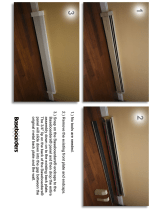
How to attach
the 120
volt
electrical assembly
Before beginning with the camera
assembly,
the electrical circuitrv should
be attached to
the baseboard.
T[rn
the
baseboard upside
down and
place
it
on a
flat,
clean
surface.
l. Attach the switch unit: Screw
the box
with the two switches firmly to
the front cen-
ter of the
lo*'er face
of the
baseboard, using
four
of the screws
provided. The
switches
must face outward, as shown.
You
will
flnd
four
screu'
holes in the
proper Ìocation.
2. Attach
the two outlet units:
Take
the cable
coming from one side of the
switch unit and
carefully lead it around the
front edge of the
nearest
baseboard
leg. Lay the cable
into the
notch
specially
provided
on the
front edge of
the leg.
About tvr.o-thirds of the
way toward the
back ofthe baseboard,
and near
its
edge,
you
will find another four screw
holes. Fasten the
outlet unit to these, using
four
more
of
the
screws
provided.
Attach the other outlet unit
to the opposite
side of the baseboard,
in
the
same
manner.
This
picture
shows
how the
fully
assem-
bled
120 volt
circuitry should
look.
A
A
How to attach
the 220-240
volt
electrical
assembly
This
circuitry
is supplied
in one solid U-
A\
shaped unit.
Simply
screw
it to the
Ìower
side of the baseboard
with the
screws
pro-
vided, as shown.

Attach camera column to baseboard
MP-4 Model XLR: Fasten
the column
post
to the
baseboard,
as shown,
using the
four nuts
and
bolts
provided.
A
special rnrench is supplied for
tightening the nuts; use
a
suitable
screwdriver
to
hoid
the bolts while
you
are doing this. The
column
post
must
be
positioned
as sholm, w'ith
the milled section
(A)
pointing
torn'ard the
center
ofthe baseboard. Slide the camera col-
umn onto the
post
and secure it fumly u'ith the
Ìocking knob
(B).
The
column
of the
Model XLR
can be
rotated
through an angÌe
of
180
degrees. For details,
see
page
32.
Wt2t
',
ft111,'::l:,::
, B
gB
,
A<tL
'#
Y
v
MP-4 Standard Model: The column is most
eas-
ily attached with the baseboard in a vertical
position
and
the column
placed
horizontalÌy.
Attach
the column to the baseboard
in
such a
way
that the
millimeter
scale
faces
toward the
baseboard.
Insert
the fow bolts, first through
the column base and
then through the base-
board.
Add
the
washers, and then the
nuts.
Tighten the nuts with the special
wrench
pro-
vided;
use a
suitable screwdriver to
hold
the
bolts
while tightening
them.
'..,&.
-1:iqft*
10
v

A
A\
A\
Camera
assembly
1. Attach vertical carriage
to column:
Loosen
the
locking Ìever
(A)
on
the carriage
by at
least one
full revoÌution.
CarefulÌy
push
the
lower
end of the carriage
onto the column, making sure that the trvo
white rollers
(B)
sÌide down behind the
rails
(c).
Lower
the carriage further, untiÌ the two
white rollers
(D)
at the top
rest
against the
top
of the column.
Slowly rotate the height adjustment lever
(E)
in
a
counterclockwise
direction and, as
the carriage
slowly
goes
down,
make
sure
the white
rollers
feed in behind the rails, as
shown.
Lower
the carriage by about
tu'o more
inches, and lock it
on the
column by tight-
ening the locking lever
(A).
A
D
11
.-\

2. Attach spring housing
and counterweight spring:
Add the spring
housing
to
the column by simply
inserting it into
the coÌumn
top, as shown, with the
spring ends
facing
the
front.
Reinsert the
pin,
being sure
that it
goes
through
the
loop
(B)
at the spring end.
Tighten the
pin.
Attach
the
counterweight
spring to the
verticaÌ
car-
riage.
Remove the
pin
(A)
by unscrewing
it
and
pulling
it out.
Wind the verticaÌ carriage
down the column, until
it is
at an easily accessible
height.
Unlock
the vertical car-
riage, bring it all the way to
the top
of
the column, and
lock
it
again.
Lock the vertical carriage in
position.
v"
\3
WARNING:
Never loosen
or remove the
pin
(A)
unless the
vertical
carriage is at the top of the column and locked
in
position.
Y"
12
\,

r-\
^\
-\
4. Put shutter
on camera:
Then
align
the smallest
of Push
the
shutter unit
onto
A,
First
screvv
the
"exposure"
the three
tabs
(B)
on
the
the camera in
that orienta-
'
cable release into
its socket
shutter
panel
u'ith
the
tion,
and rotate it in
a clock-
(A).
smailest
of the cut-outs
(C)
wise
direction
until
it
comes
on the camera
body.
to a
firm
stop.
3. Attach camera body to
vertical
carriage: Loosen
the
knob
(A)
until
it
is in a verti-
cal
position,
as show-n. Also
loosen
the screw
(B)
by
about
three
rotations.
Push
the
camera body
on alÌ
the vgay,
as shou'n. Rotate
it
back and forth
slightly,
until
you
feel
it
click into
the
true
vertical position.
Tighten
(B)
and then
(A).
CAUTION:
When
there is no lens
on the shut-
ter,
the shutter
blades are exposed
and
unprotected.
They
are very delicate;
do not
touch them.
5. Attach lens
to shutter:
Carefully screu'the
lens
that is to
be used into the shutter in
the
manner
shown.
a\

Assembly
and
use of the
sliding camera head
Assembly:
1.
Hook the
camera head
onto the left
side
ofthe camera
body,
as shown.
2. Lower
the
head
carefully, taking
care
that
the
pins
(A)
engage in
the
corresponding
holes
on the camera
body.
3. Lock
the head in
place
by
pushing
the
latch
(B)
in
toward the
camera bodv.
How
the camera head
slides: To
place
the
left
opening in
the head
(the
vieu'ing
position)
over
the camera lens,
depress
the button
(C)
and,
while holding it
in,
push
the head
to the
right
as far
as
it
will
go.
To
pÌace
the
right
opening
(the
picture-taking
position)
over
the lens,
depress the
button
(D)
and
push
the
head
all the way
to the left.
t4
v"
v-
b.
Y"
\É

a\
-\
.q
{-\
4. Connect
the long
"pre-view"
cable release:
Do this with
the camera
head in the
picture-
taking
position.
It
should be
pushed
all
the
way
to the
left.
Attach
the
release
to the shutter, by
screwing it into
the
"pre-view"
socket
(E).
Set the lens at its largest
aperture
(small-
est f-number).
Look at the shutter from above; the shut-
ter blades should be fully cÌosed. Now
push
the head alÌ the way
to the
right, to the view-
ing
position.
The
shutter blades should open
fully.
If
the above does not happen,
you
should adjust the
plunger
end
(F)
of the
release in
one direction or the other, until the
shutter
functions
as described.
WARNING:
When
using the sliding camera
head
together with heavy accessories, such
as one
or two
macro
extensions, aÌrvays
lock
the vertical
carriage on the column as soon as
you
have raised
or lowered the camera.
If
you
do not,
the camera
may
begin to slide
down the column,
due to the extra
weight.
5. Attach the
ground glass:
One
end
of the
ground glass
frame has
two small
protrusions
(G)
near its
base. Hold the frame
in
the left
hand, with
the
protrusions
pointing
to the
left.
Slide the
ground glass
frame into the camera
head from
the left, as shown. SÌide
it in
all
the way,
so that the two retainer
pins
on the
ground glass
frame engage securely
in
the
two spring Ìoops on the camera
head.
a\
15

Assembly
and
use
of the
44-40
fixed
camera
head
1. Attachment:
Hold
the head
so that
the
hinges
of the two latches
(A)
are nearest you.
Open the latches,
as
shown.
Place
the head
on the
camera
body. Be
sure
it is
seated
correctly. Push
in
the tu'o Ìatches
(A)
to lock the head
in
pÌace.
2.
Connect the long
"pre-view"
cable release:
Attach
it first
to the shutter,
by screu,ing
it
into
the
"pre-view"
socket
(B).
Set the lens
to
its
largest
aperture
(small-
est f-number).
Then
attach the
plunger
end
of the release
to
the camera
head, in
the following
u,'ay.
Pull
out
the arm
(C)
as far
as
it
will
go.
While
holding
it there, insert
the
plunger
end ofthe
cable
release in
the way
shou,n.
Secure
the
plunger
end firmly
with the
two nuts
(D).
\r"
Y"
Y-
16
\3

à
Slowly
release the arm
(C).
Its movement
should depress the
plunger
and cause
the
shutter to open
fulÌy.
-\
Insertion of a
film holder will cause the arm
(C)
to be
pushed
out again.
This should cause
the tension
in
the cable
release to be
relaxed
sufflciently
for the shutter to close
fully.
{^
If the shutter blades do
not open fully when
the arm
(C)
is relaxed,
or
do not close
fully
when that arm
is
pulled
out, then
you
should
adjust the
plunger
end
(D)
of the
release in
one direction
or the other, until
the shutter
functions as required.
-\
3. Attach
the
ground glass:
First, remove
the U-shaped
adapter
(shown
on
page
26)
from the
camera head.
Hold the
frame in
the
right
hand, with the
small
protrusions
(E)
pointing
to
the right.
Slide the
ground
glass
frame
into the cam-
era head
from
the
right. Slide
it in all the
way, so that
the two retainer
pins
on the
ground
glass
frame
engage
securely
in the
two spring
loops
on the camera
head.
17

Assembly
and use
of the
44-44
fixed
camera head
l. Attachment: Hold
the head
so that
the
hinges
ofthe two latches
(A)
are nearest you.
Open the
latches,
as shown.
Place
the
head
on
the camera
body. Be
sure
it is
seated correctly.
Push in
the two latches
(A)
to
lock
the head in
place.
2.
Connect the long "pre-view"
cable
release:
Attach it
first to the
shutter, by
screwing it
into
the
"pre-view"
socket
(B).
Set
the
Ìens
to its largest
aperture
(small-
est f-number).
Then
attach
the
plunger
end ofthe release
to
the camera head
in
the
folÌowing
way: Turn
the knob
(C)
counterclockwise
so that the
pin
(D)
is
in a retracted position.
Insert
the
plunger
end of
the cable release
as shown
(the
tip of the
plunger
should
touch the
pin).
Secure the
plunger
end firmly
with
the two
nuts
(E).
Y,
\"
Yt
\,
18
\r,

Turn the knob
(C)
clockwise.
The
pin
should depress the
plunger
and cause
shutter
to open fully.
-\
Ifthe shutter blades do not open
fuÌly, adjust
the
plunger
end
(l')
of the
release until the
shutter
functions
as
required.
-\
3.
Attach the
ground glass:
HoÌd the
ground
glass
frame in the right hand,
with the small
protrusions
(G)
pointing
to
the
right. Turn
the
knob
(C)
counterclockwise
as
far
as
it
will
go,
against the
pressure
of the
spring. This
wilÌ raise the arms
(H).
r\
Starting
with the side
farthest away
from
you,
slide the
retainer
pin
of the
ground
glass
frame
into
the opening of
the arm.
Now slide
the nearer
pin
into the
nearer arm.
If neces-
sarv. null the arm out and
over as
shown.
^
Note: Due to the locking system
on this
cam-
era
head,
some earlier
model
MP-4
ground
glass
frames
may not flt
properly and should
not be used.
(D)
the
î
19

Assembly
of
lighting
system
1. Fasten
lamp arms
to
baseboard:
The
two
lamp
arms must
be fastened
to the left
and
right
sides of the
baseboard.
Use the special
locations
near
the rear
edge
of
the
baseboard.
The locking
lever
(A)
on each lamp
arm
should face
the front
of the baseboard,
as
shown. Fasten
the Ìamp
arms
securely
to the
baseboard,
using
the screws
supplied
with
the arms.
2. Angle lamp
arms
correctly:
Angle
them as
indicated
by the two marks
(B),
and lock
them in
position
with the lever
(A).
This
set-
ting will
give you
the lamp
position
that is
suitable for most
general
copy work.
For
speciaÌ lighting requirements,
the lamp
arms
may
be angled in any way
desired.
(See
page
22.)
I,
\F
"l>
\
RIGHT.HAND LAMPARM.
MP-4 MODEL
XLR.
RIGHT-HAND
LAMP
ARM.
MP-4
STANDARD
MODEL.
Note:
Dimension
A is slightly
longer
than
dimension
B.
Correct
location
of
cross
bars and
lamps: The
diagrams
above show
the correct location
of
arms
and
lamps
for
each camera model.
20
:"
/