Visonic POWERMASTER-10 Installer's Manual
- Category
- Security access control systems
- Type
- Installer's Manual
This manual is also suitable for

PowerMaster-10/
PowerMaster-30
Fully supervised wireless alarm control system
Fully supervised wireless alarm control system Fully supervised wireless alarm control system Fully
supervised wireless alarm control system Fully supervised wireless alarm control system Fully supervised
wireless alarm control system Fully supervised wireless alarm control system Fully supervised wireless
alarm control system Fully supervised wireless alarm control system Fully supervised wireless alarm
control system Fully supervised wireless alarm control system Fully supervised wireless alarm control
system Fully supervised wireless alarm control system Fully supervised wireless alarm control system
Fully supervised wireless alarm control system Fully supervised wireless alarm control system Fully
Installer Guide

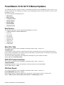
D-303222 PowerMaster-10/30 G2 Installer's Guide 1
PowerMaster-10/30 G2
Version 15
Installer's Guide
Table of Contents
1. INTRODUCTION ................................................. 3
1.1 System Features .......................................... 3
2. CHOOSING THE INSTALLATION LOCATION .. 7
3. POWERMASTER-10 G2 INSTALLATION .......... 8
3.1 Opening the PowerMaster-10 G2 Control
Panel and Bracket Mounting ............................. 8
3.2 Connecting to the Telephone Line .............. 9
3.3 System Planning & Programming............. 10
3.4 GSM Module Installation ........................... 10
3.5 PGM-5 Installation ...................................... 11
3.6 Adding Wired Zones or PGM Device ........ 12
3.7 Connecting Power to the Control Panel ... 13
3.8 Supplying Power to the Unit ..................... 15
3.9 Closing the PowerMaster-10 G2 Control
Panel ................................................................. 15
4. PowerMaster-30 G2 INSTALLATION .............. 16
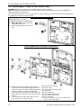
4.1 Opening the PowerMaster-30 G2 Control
Panel and Bracket Mounting ........................... 16
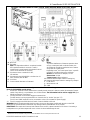
4.2 Connecting to the Telephone Line ............ 17
4.3 Connecting Wired Zone and Special Siren
........................................................................... 18
4.4 System Planning & Programming............. 18
4.5 GSM Module Installation ........................... 19
4.6 PGM-5 Installation ...................................... 20
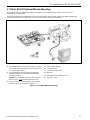
4.7 DUAL RS-232 Optional Module Mounting 21
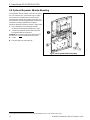
4.8 Optional Expander Module Mounting ....... 22
4.9 Connecting AC Power to the Control Panel
........................................................................... 24
4.10 Supplying Power to the Unit ................... 25
4.11 Closing the PowerMaster-30 G2 Control
Panel ................................................................. 26
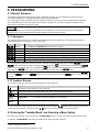
5. PROGRAMMING .............................................. 27
5.1 General Guidance ....................................... 27
5.1.1 Navigation .......................................... 27
5.1.2 Feedback Sounds ............................... 27
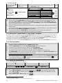
5.2 Entering the "Installer Mode" and Selecting
a Menu Option .................................................. 27
5.2.1 Entering the "Installer Mode" if "User
Permit" is enabled ....................................... 28
5.2.2 Selecting options ................................ 28
5.2.3 Exiting the Installer Mode ................... 28
5.3 Setting Installer Codes ............................... 29
5.3.1 Identical Installer and Master Installer
Codes .......................................................... 29
5.4 Zones / Devices .......................................... 30
5.4.1 General Guidance & Zones/Devices
Menu Options .............................................. 30
5.4.2 Adding New Wireless Devices or Wired
Sensors ....................................................... 30
5.4.3 Deleting a Device ............................... 33
5.4.4 Modifying or Reviewing a Device ........ 34
5.4.5 Replacing a Device ............................. 34
5.4.6 Defining Configuration Defaults for
"Device Settings" ......................................... 35
5.4.7 Updating Devices after Exiting Installer
Mode ........................................................... 35
5.5 Control Panel .............................................. 35
5.5.1 General Guidance – "Control Panel"
Flow-Chart & Menu Options ........................ 35
5.5.2 Configuring Arming/Disarming and
Exit/Entry Procedures .................................. 36
5.5.3 Configuring Zones Functionality ......... 37
5.5.4 Configuring Alarms & Troubles ........... 38
5.5.5 Configuring Sirens Functionality ......... 39
5.5.6 Configuring Audible & Visual User
Interface ...................................................... 39
5.5.7 Configuring Jamming and Supervision
(Missing device) .......................................... 41
5.5.8 Configuring Miscellaneous Features ... 42
5.6 Communication .......................................... 42
5.6.1 General Guidance – "Communication"
Flow-Chart & Menu Options .......................... 42

2 D-303222 PowerMaster-10/30 G2 Installer's Guide
5.6.2 Configuring PSTN (landline phone)
Connection .................................................. 43
5.6.3 Configuring GSM-GPRS (IP) - SMS
Cellular Connection ..................................... 44
5.6.4 Configuring Events Reporting to
Monitoring Stations ..................................... 45
5.6.5 Configuring Events Reporting to Private
Users .......................................................... 49
5.6.6 Configuring Motion Cameras for Visual
Alarm Verification ........................................ 49
5.6.7 Configuring Upload / Download Remote
Programming Access Permission ............... 50
5.7 PGM Output ................................................ 51
5.7.1 General Guidance .............................. 51
5.7.2 Open Collector States ........................ 51
5.7.3 Configuring a PGM device ................. 51
5.7.4 Entering Daytime Limits ..................... 52
5.7.5 PGM Output Configuration ................. 52
5.8 Custom Names ........................................... 53
5.8.1 Custom Zone Names ......................... 53
5.8.2 Record Speech .................................. 53
5.8.3 Voice Box Mode
1
................................ 54
5.9 Diagnostics ................................................. 54
5.9.1 General Guidance – "Diagnostics" Flow-
Chart & Menu Options ................................ 54
5.9.2 Testing Wireless Devices ................... 55
5.9.3 Testing the GSM module ................... 56
5.10 User Settings ............................................ 56
5.11 Factory Default ......................................... 57
5.12 Serial Number ........................................... 57
5.13 Start UL/DL ............................................... 57
5.14 Partitioning ............................................... 58
5.14.1 General Guidance – "Partitioning"
Menu ........................................................... 58
5.14.2 Enabling / Disabling Partitions .......... 58
5.15 Operation Mode ........................................ 58
5.15.1 General Guidance – "Operation Mode"
Menu ........................................................... 58
5.15.2 Select between EN-50131, DD243 and
BS8243 ....................................................... 58
5.15.3 BS8243 Setup .................................. 58
5.15.4 DD243 Setup ................................... 60
6. PERIODIC TEST ............................................... 61
6.1 General Guidance ...................................... 61
6.2 Conducting a Periodic Test ....................... 61
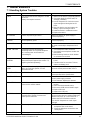
7. MAINTENANCE ................................................ 63
7.1 Handling System Troubles ........................ 63
7.2 Dismounting the Control Panel ................. 64
7.3 Replacing the Backup Battery ................... 64
7.4 Fuse Replacement ...................................... 64
7.5 Replacing/Relocating Detectors ................ 64
7.6 Annual System Check ................................ 64
8. READING THE EVENT LOG ............................. 65
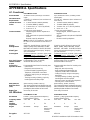
APPENDIX A. Specifications ............................... 66
A1. Functional ................................................... 66
A2. Wireless ...................................................... 66
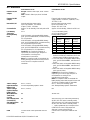
A3. Electrical ..................................................... 67
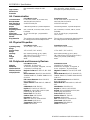
A4. Communication .......................................... 68
A5. Physical Properties .................................... 68
A6. Peripherals and Accessory Devices ......... 68
APPENDIX B. Working with Partitions ................ 69
B1. User Interface and Operation .................... 69
B2. Common Areas ........................................... 69
APPENDIX C. Detector Deployment & Transmitter
Assignments......................................................... 70
C1. Detector Deployment Plan ......................... 70
C2. Keyfob Transmitter List ............................. 71
C3. Emergency Transmitter List ...................... 71
C4. Non-Alarm Transmitter List ....................... 72
APPENDIX D. Event Codes .................................. 72
D1. Contact ID Event Codes ............................. 72
D2. SIA Event Codes ........................................ 72
D3. Understanding the Scancom Reporting
Protocol Data Format ....................................... 73
D4. SIA over IP - Offset for Device User .......... 73
APPENDIX E. Glossary ........................................ 73
APPENDIX F. Compliance with Standards ........... 75

1. INTRODUCTION
D-303222 PowerMaster-10/30 G2 Installer's Guide 3
1. INTRODUCTION
PowerMaster-10 G2 and PowerMaster-30 G2 are PowerG-enabled professional all-in-one wireless security, fire and
safety systems supporting advanced applications and Visonic's new revolutionary PowerG™ Two-Way, Time Division
Multiple Access (TDMA) and Frequency Hopping Spread Spectrum (FHSS) wireless technology. This offers unmatched
wireless robustness, superior range and long battery life; a perfect and user friendly solution for both monitoring service
providers and professional installers.
This manual refers to PowerMaster-10/30 G2 v15 and above. The most updated manuals can be downloaded from the
Visonic Web site http://www.visonic.com.
Note: "Pmaster" is used as an abbreviation for "PowerMaster".
The PowerMaster-10/30 G2 control panel is supplied with 2 instruction manuals:
Installer's Guide (this manual) – for use of system installer during system installation and configuration
User’s Guide -– also for use of system installer during system installation and configuration, but also for the master
user of the system, once installation is completed. Hand over this manual to the master user of the system.
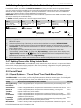
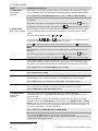
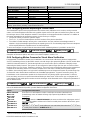
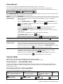
1.1 System Features
The following table lists the PowerMaster features with a description of each feature and how to use it.
Feature
Description
How to configure and use
Visual Alarm
Verification
The PowerMaster when used with Next CAM
PG2 PIR-camera detector and GPRS
communication is able to provide the
Monitoring Station with clips captured in
alarm situations. The system sends the clips
to the Monitoring Station automatically for
burglary alarms and, depending on setup,
also for fire and personal emergency alarms.
1. Setup GPRS communication: see GSM
Module Installation (section 3.4 for
PowerMaster-10 G2 or section 4.4 for
PowerMaster-30 G2)
2. Configure camera settings: refer to the
Next CAM PG2 Installation Instructions
3. Enable fire and personal alarm
verification: see section 5.6.6 Configuring
Motion Cameras for Video Alarm Verification
On demand clips from
cameras
The PowerMaster can provide images from
the Next CAM PG2 by demand from a
remote PowerManage server. Pictures are
taken based on a command from the
monitoring station. To protect customers'
privacy, the system can be customized to
enable the "On Demand View" only during
specific system modes (i.e. Disarm, Home &
Away) and also to a specific time window
following an alarm event.
1. Setup the On demand feature: see
section 5.6.6 Configuring Motion Cameras
for Video Alarm Verification
2. To request and view images: refer to the
PowerManage User's Guide, Chapter 5
Viewing and Handling Events
Easy Enrollment
PowerG devices are enrolled from the control
panel. "Pre-enrollment" can also be
performed by entering the PowerG device ID
number and then activating the device in the
vicinity of the panel.
To enroll or pre-enroll devices: see section
5.4.2 Adding New Wireless Devices or Wired
Sensors
Device Configuration
Device parameters and related system
behavior can be configured from the control
panel or from a remote location.
Each PowerG device has its own settings
which can be configured through the control
panel by entering the "DEVICE SETTINGS"
menu.
To configure devices from the control
panel: see Chapter 5 Programming and also
the individual device's Installation
Instructions.
To configure devices from a remote
location: refer to the PowerManage User's
Guide Chapter 3 Working with Panels and to
the Remote Programmer PC software User's
Guide, Chapters 6 and 7.

1. INTRODUCTION
4 D-303222 PowerMaster-10/30 G2 Installer's Guide
Diagnostics of the
control panel and
peripherals
You can test the function of all wireless
sensors deployed throughout the protected
area, to collect information about the
received signal strength from each
transmitter and to review accumulated data
after the test.
To perform diagnostics and to obtain
signal strength indication: see section 5.9
Diagnostics
Conducting periodic
tests
The system should be tested at least once a
week and after an alarm. The periodic test
can be conducted locally or from a remote
location (with the assistance from a non-
technical person in the house).
To conduct a walk test locally: see
Chapter 6 Periodic Test
To conduct a walk test from remote
location: refer to the Remote Programmer
PC software User's Guide, Chapter 6 Data
Details Tables.
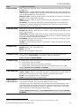
Partitions
1
The partitioning feature, when enabled,
divides your alarm system into distinct areas
each of which operates as an individual
alarm system. Partitioning can be used in
installations where shared security systems
are more practical, such as a home office or
warehouse building.
1. Enable partitioning: see section 5.14
Partitioning
2. Setup partition association for each
device: see section 5.4.2 Adding New
Wireless Devices or Wired Sensors
To understand more about partitioning:
see APPENDIX B. Working with Partitions
and APPENDIX A. in the User's Guide.
Two-way voice
communication
2
The PowerMaster system enables voice
communication with Monitoring Stations
To enable and configure two way voice:
see section 5.6.4 Configuring Events
Reporting to Monitoring Stations
Device configuration
templates
The default parameters with which a new
device is enrolled into the system can be set
before you enroll devices. This default
template saves time on device configuration.
1. Define enrollment defaults for devices:
see section 5.4.6 Defining Configuration
Defaults for "Device Settings"
2. Enroll or pre-enroll devices: see section
5.4.2 Adding New Wireless Devices or Wired
Sensors
SirenNet - distributed
siren using Smoke
detectors
All PowerG smoke detectors are able to
function as sirens, alerting on any of 4 types of
alarm in the system: burglary, gas, fire or
flood.
Enable and configure SirenNet for each
smoke detector: refer to the SMD-426 PG2
/ SMD-427 PG2 Installation Instructions
Integrated Siren built
into the panel
The control panel has a high-powered built-in
siren that sounds in case of alarm, enabled by
default.
To define whether or not the control
panel's siren will sound upon alarms: see
section 5.5.5 Configuring Sirens Functionality
Wired Siren outputs
The control panel can operate a wired siren
and strobe devices
Install and connect wired siren: see
section 4.7 Optional Expander Module
Mounting
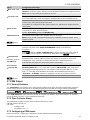
Wired zones and
programmable
outputs (PGM)
The control panel can support wired detectors
and control automation devices with
programmable wired outputs.
1. Connect a wired zone or PGM device:
see section 3.6 Adding a Wired Zone or
PGM.
2. Program the wired zone: see section
5.4.2 Adding New Wireless Devices or Wired
Sensors
3. Program PGM outputs behavior: see
section 5.7 PGM Output.
1
Refers to PowerMaster-30 G2
2
Refers to PowerMaster-30 G2 with voice option only

1. INTRODUCTION
D-303222 PowerMaster-10/30 G2 Installer's Guide 5
Reporting to Private
Users and/or
Monitoring Station by
telephone, SMS and
IP communication
The PowerMaster system can be
programmed to send notifications of alarm
and other events to 4 private telephone
subscribers by voice and also to 4 SMS
cellular phone numbers and to report these
events to the Monitoring Station by SMS,
PSTN or IP communication.
To configure notifications to Private
phones: refer to the PowerMaster-10/30 G2
User's Guide, Chapter 6, section C.11
Programming Private Phone and SMS
Reporting
To configure reporting to the Montioring
Station: see section 5.6.4 Configuring
Events Reporting to Monitoring Stations
Quick installation with
link quality indication
With PowerG devices, there is no need to
consult the control panel when mounting a
wireless device, because PowerG devices
include a built-in link quality indicator.
Choosing the mounting location is a quick
and easy process.
To choose the ideal location to mount a
wireless device, see Chapter 2 Choosing the
Installation Location.
Device Locator
Helps you to easily identify the actual device
displayed on the LCD display.
To read more on the Device Locator: refer
to the PowerMaster-10/30 G2 User's Guide,
Chapter 2, Operating the PowerMaster
System
To use the device locator when bypassing
a zone or when clearing a bypassed zone:
refer to the PowerMaster-10/30 G2 User's
Guide, Chapter 6, section C.1 Setting the
Zone Bypass Scheme
To use the device locator when
conducting the periodic test: see Chapter
6 Periodic Test or refer to the PowerMaster-
10/30 G2 User's Guide, Chapter 9 Testing
the System
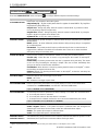
Guard key-safe
PowerMaster is able to control a safe that
holds site keys that are accessible only to the
site's guard or Monitoring Station's guard in
the event of an alarm.
1. Connect the safe to the panel: see
section 3.6 Adding Wired Zones or PGM
Device, Figure 3.6b (PowerMaster-10 G2) /
section 4.7 Optional Expander Module
Mounting, Figure 4.8b (PowerMaster-30 G2)
2. Configure the safe's zone type to
"Guard Zone": see section 5.4.2 Adding
New Wireless Devices or Wired Sensors
3. Setup guard code: see section 5.3
Setting Installer Codes
Arming key
External system may control arming and
disarming of the PowerMaster system
1. Connect the external system output to
the panel: see section 3.6 Adding Wired
Zones or PGM Device, Figure 3.6b
(PowerMaster-10 G2) / section 4.7 Optional
Expander Module Mounting, Figure 4.8b
(PowerMaster-30 G2)

1. INTRODUCTION
6 D-303222 PowerMaster-10/30 G2 Installer's Guide
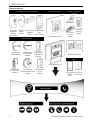
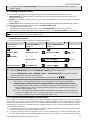
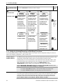
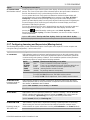
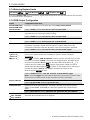
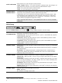
System Architecture:
Security Detectors and Transmitters
Main Control Panels
Keyfobs, Keypad and
Keyprox
Next CAM
PG2 Motion
Detector
with Camera
Next PG2
Motion
Detector
MC-302 PG2
Magnetic
Contact
TOWER-30AM
PG2
Mirror Detector
PowerMaster-10 G2
PowerMaster-30 G2
KF-234 PG2
KF-235 PG2
Two-way
Keyfobs
KP-140 PG2
Two-way
Keypad
Safety Detectors
KP-160 PG2 Keyprox
SMD-426 PG2
Smoke Detector
SMD-427 PG2
Smoke & Heat
Detector
TMD-560 PG2
Temperature
Detector
GSD-441 PG2
Gas (Methane)
Detector
GSD-442 PG2
Carbon Monoxide (CO)
Detector
FLD-550 PG2
Flood
Detector
Sirens
SR-730 PG2
Outdoor
Siren
SR-720 PG2
Indoor Siren

2. CHOOSING THE INSTALLATION LOCATION
D-303222 PowerMaster-10/30 G2 Installer's Guide 7
2. CHOOSING THE INSTALLATION LOCATION
To ensure the best possible mounting location of the PowerMaster control panel, the following points should be
observed:
The selected location should be approximately in the center of the installation site between all the transmitters,
preferably in a hidden location.
In close proximity to an AC source
In close proximity to a telephone line connection (if PSTN is used)
Where there is good cellular coverage, if GSM-350 PG2 is used
Far from sources of wireless interference, such as:
o Computers or other electronic devices, power conductors, cordless phones, light dimmers, etc.
o Large metal objects (such as metal doors or refrigerators)
Note: A distance of at least 1 meter (3 ft) is recommended.
If using the panel's built-in siren and/or voice, select location where audio can be heard throughout the premises.
When mounting wireless devices:
Make sure that the signal reception level for each device is either "Strong" or "Good", but not "Poor".
Wireless magnetic contacts should be installed in a vertical position and as high up the door or window as possible.
Wireless PIR detectors should be installed upright at the height specified in their Installation Instructions
Repeaters should be located high on the wall in mid-distance between the transmitters and the control panel.
WARNING! To comply with FCC and IC RF exposure compliance requirements, the control panel should be located at
a distance of at least 20 cm from all persons during normal operation. The antennas used for this product must not be
co-located or operated in conjunction with any other antenna or transmitter.
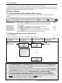
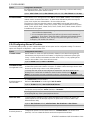
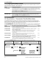
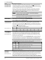
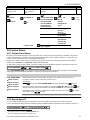
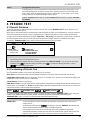
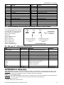
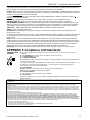
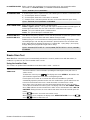
Customer Premises Equipment and Wiring
A
B
C
D
E
F
G
H
I
E
E
H
J
A. Network Service Provider's Facilities
F. Alarm Dialing Equipment
B. Telephone Line
G. Answering System
C. Network Demarcation Point
H. Unused RJ-11 Jack
D. RJ-31X Jack
I. Fax Machine
E. Telephone
J. Computer
Note: The REN is used to determine the number of devices that may be connected to a telephone line. Excessive RENs on a telephone line
may result in the devices not ringing in response to an incoming call. In most but not all areas, the sum of RENs should not exceed five (5.0).
To be certain of the number of devices that may be connected to a line, as determined by the total RENs, contact the local telephone
company.
Connection to telephone company provided coin service is prohibited. Connection to party lines service is subject to state tariffs.
The installer should verify line seizure. Be aware of other phone line services such as DSL. If DSL service is present on the
phone line, you must install a filter. It is suggested to use the DSL alarm filter model Z-A431PJ31X manufactured by
Excelsus Technologies, or equivalent. This filter simply plugs into the RJ-31X jack and allows alarm reporting without
breaking the internet connection.

3. POWERMASTER-10 G2 INSTALLATION
8 D-303222 PowerMaster-10/30 G2 Installer's Guide
3. POWERMASTER-10 G2 INSTALLATION
Required tool: Philips screwdriver #2.
PowerMaster-10 mounting process is shown in Figures 3.1 - 3.9.
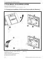
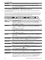
3.1 Opening the PowerMaster-10 G2 Control Panel and Bracket Mounting
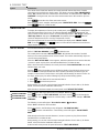
Figure 3.1 – Back Unit Mounting
To Mount the Unit:
1. Release the screws
A. Mounting surface
2. Remove the front cover
B. Back unit
3. Mark 4 drilling points on the mounting surface
4. Drill 4 holes and insert wall anchors
5. Fasten the back unit with 4 screws
WARNING! When plugging SIREN & ZONE terminals back into place, be sure to align them carefully with the pins on the
PCB. Misaligned or reverse insertion of terminals may cause internal damage to the PowerMaster-10 G2!

3. POWERMASTER-10 G2 INSTALLATION
D-303222 PowerMaster-10/30 G2 Installer's Guide 9
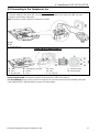
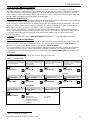
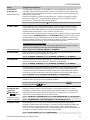
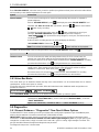
3.2 Connecting to the Telephone Line
PHONE WIRING
Connect the telephone cable to the SET connector and connect the telephone line cable to the LINE connector
(through the desired wiring cable entry).
Note: The telephone cable should be no longer than 3 meters.
A. SET
B. LINE
C. Tel line wall jack
PHONE WIRING IN NORTH AMERICA
A. SET
G. Green
B. LINE
H. Brown
C. RJ-31X cord
I. RJ-31X jack
D. 8-position RJ-31X plug
J. Line from street
E. Gray
K. House phones
F. Red
Figure 3.2 –Phone Wiring
This equipment is designed to be connected to the telephone network using an RJ11 connector which complies with
Part 68 rules and requirements adopted by ACTA and a properly installed RJ31X connector. See drawing above for
details.
In the case that RJ31X is not available (consult your telephone company or a qualified installer), the telephone line
should be connected to the PowerMaster-10 G2 unit first and then all other home equipment should be connected to
the PowerMaster-10 G2 "Phone" outlet.

3. POWERMASTER-10 G2 INSTALLATION
10 D-303222 PowerMaster-10/30 G2 Installer's Guide
3.3 System Planning & Programming
Program the system now as instructed in the programming section.
The tables in APPENDIX C will help you plan and record location of each detector, the holder and assignment of each
transmitter.
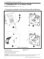
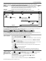
3.4 GSM Module Installation
The internal GSM 350 module enables the PowerMaster-10 G2 system to operate over a GSM/GPRS cellular network
(for further details, see the GSM 350 PG2 Installation Instructions).
The GSM modem auto detection feature enables automatic enrollment of the GSM modem into the PowerMaster-10
G2 control panel memory. GSM modem auto detection is activated in one of two ways: after tamper restore and after
reset (power-up or after exiting the installer menu). This causes the PowerMaster-10 G2 to automatically scan GSM
COM ports for the presence of the GSM modem.
In the event that the GSM modem auto detection fails and the modem was previously enrolled in the PowerMaster-10
G2 control panel, the message "Cel Remvd Cnfrm" will be displayed. This message will disappear from the display only
after the user presses the button. The modem is then considered as not enrolled and no GSM trouble
message will be displayed.
Note: A message is displayed only when the PowerMaster-10 G2 alarm system is disarmed.
Plug in the GSM module and fasten it as shown in the
above drawing.
A. GSM
B. Front unit
Caution! Disconnect both batteries and AC power before
installing or removing the GSM module or SIM card.
Insert the SIM card into the GSM module as shown in the
above drawing.
1. Slide top cover.
2. Open cover
3. Align SIM card in cover (note cover orientation)
4. Slide SIM card into cover
5. Rotate cover to close
6. Lock cover to close
IMPORTANT! Do not insert or remove SIM card when the
control panel is powered by AC power or battery.
Figure 3.4 – Optional GSM Module Mounting and SIM Card Insertion

3. POWERMASTER-10 G2 INSTALLATION
D-303222 PowerMaster-10/30 G2 Installer's Guide 11
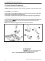
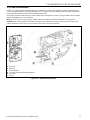
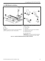
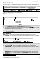
3.5 PGM-5 Installation
PGM-5 is an output interface module designed to provide alarm, trouble events and status signals to external devices
such as long range wireless monitoring transmitters, CCTV systems, home-automation systems and LED annunciation
panels (for further details see the PGM-5 Installation Instructions).
The PGM-5 provides 5 solid state relay contact outputs and is designed to be used as a plug-in internal add-on module
with the PowerMaster-10 G2 control panel.
Note: The PGM-5 will be active only if the PGM-5 option was enabled in the factory default of the control panel.
Caution! When mounting the PGM-5 module it is strongly recommended to route the cable as shown in Figure 3.5 to
prevent interference which may occur if routed too close to the control panel antennas.
A. Front unit
B. Back unit
C. PGM-5 Module
D. 2 Screws for fastening the PGM-5 Module
E. Flat cable
F. Wiring
Figure 3.5 – PGM-5 Module Mounting

3. POWERMASTER-10 G2 INSTALLATION
12 D-303222 PowerMaster-10/30 G2 Installer's Guide
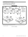
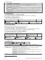
3.6 Adding Wired Zones or PGM Device
Required tools: Cutter and slotted screwdriver - 3 mm blade.
PowerMaster-10 G2 wiring is shown in Figures 3.6a – 3.7b.
CABLES ROUTING GUIDE
A. Cables entry options
B. Back unit
C. Cable clips
To Route the Cable:
1. Remove the left or
right side cables
entry knockout(s)
and enter the
required cable(s)
2. Remove and use as
cable clamp(s)
To Route the Cable (continued):
3. Position the clamp (1 of 2) as shown and then rotate into place.
4. Using a slotted screwdriver press downward gently on the point illustrated in the drawing. Make sure the clamp is
locked (a click is heard).
Figure 3.6a – Cable Wiring

3. POWERMASTER-10 G2 INSTALLATION
D-303222 PowerMaster-10/30 G2 Installer's Guide 13
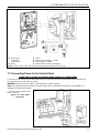
PGM AND ZONE WIRING
A. PGM output
Vmax=30v
Imax=100mA
C. Device
D. External power supply 5 - 30VDC
E. Wired detector's Tamper
B. Relay
F. Wired detector's alarm or arming key
Note: Do not use mains cable other than that supplied by the manufacturer (3 m long).
Figure 3.6b – PGM & Zone Wiring
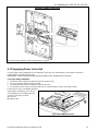
3.7 Connecting Power to the Control Panel
CONNECTING AC POWER TO CONTROL PANEL USING AC/AC TRANSFORMER
Connect the power cable and close the control panel as shown below. Electrical socket-outlet shall be installed near
the equipment and shall be easily accessible.
WARNING! DO NOT USE AN OUTLET CONTROLLED BY A WALL SWITCH.
Note: This equipment should be installed in accordance with Chapter 2 of the National Fire Alarm Code, ANSI/NFPA 72,
(National Fire Protection Association).
Connect the power adapter to the
power connector.
Figure 3.7a - Power Cable
Connection

3. POWERMASTER-10 G2 INSTALLATION
14 D-303222 PowerMaster-10/30 G2 Installer's Guide
CONNECTING AC POWER USING INTERNAL AC/DC POWER SUPPLY UNIT
PERFORM STEPS 1 and 2 ON A WORKBENCH BEFORE THE MOUNTING
1. Extract either plastic segment (will be used later)
7. Fasten power cable by clamp (extracted in step 2)
2. Extract plastic segment (will be used later)
8. Close power supply terminals cover
3. Knock out the plastic segment (left or right, according
to the power wiring direction)
9. Connect the DC output cable plug into the DC input
socket located on the front panel.
4. Remove power supply terminals cover (E)
A. Internal AC/DC power supply unit
B. Power cable clamp options
C. For thin cable
D. For thick cable (reversed clamp)
E. Terminals cover
F. DC input socket on front panel
G. DC output cable
5. Insert the power cable through the desired wiring
channel, route it to the power supply unit and connect
its 2 wires to the power supply terminal block with a
screwdriver. Fasten the screws tightly.
Verify that the wires are properly fastened!
6. Insert plastic cap to the power cable entry (extracted
in step 1)
Figure 3.7b – Power Cable Wiring

3. POWERMASTER-10 G2 INSTALLATION
D-303222 PowerMaster-10/30 G2 Installer's Guide 15
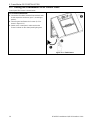
3.8 Supplying Power to the Unit
Connect power to the PowerMaster-10 G2 temporarily (see Figure 3.7a). Alternatively, you may power up from the
backup battery, as shown in Figure 3.8.
Disregard any “trouble” indications pertaining to lack of battery or lack of telephone line connection.
For Europe Safety Compliance:
a. The model shall be installed according to the local electrical code.
b. The circuit breaker shall be readily accessible.
c. The rating of the external circuit breaker shall be 16A or less.
d. The cables for the AC mains connection shall have an overall diameter of 13mm and 16mm conduit.
Please refer to Figure 3.7a "Power Cable Connection".
Figure 3.8 – Connecting Power to the Control Panel
Inserting Backup Battery:
Connect battery pack as shown in
Figure 3.8.
1. Insert battery
2. Connect the battery
3.9 Closing the PowerMaster-10 G2 Control Panel
Control panel final closure is shown below.
Figure 3.9 - Final Closure
To Close the Control Panel:
1. Close the front cover
2. Fasten the screws

4. PowerMaster-30 G2 INSTALLATION
16 D-303222 PowerMaster-10/30 G2 Installer's Guide
4. PowerMaster-30 G2 INSTALLATION
Required tool: Philips screwdriver #2.
PowerMaster-30 G2 mounting process is shown in Figures 4.1 - 4.11.
4.1 Opening the PowerMaster-30 G2 Control Panel and Bracket Mounting
Figure 4.1 – Back Unit Mounting
To Mount the Unit:
A. Mounting surface
1. Release the screws (1 of 2 is shown in Figure 4.1)
B. Back unit
2. Remove the front cover
3. Mark 4 drilling points on the mounting surface
4. Drill 4 holes and insert wall anchors
5. Fasten the back unit with 4 screws

4. PowerMaster-30 G2 INSTALLATION
D-303222 PowerMaster-10/30 G2 Installer's Guide 17
4.2 Connecting to the Telephone Line
PHONE WIRING
Connect the telephone cable to the SET connector and connect the telephone line cable to the LINE connector
(through the desired wiring cable entry).
Note: The telephone cable should be no longer than 3 meters.
A. LINE
B. SET
C. Tel line wall jack
PHONE WIRING IN NORTH AMERICA
A. LINE
B. SET
C. RJ-31X cord
D. 8-position RJ-31X plug
E. Brown
F. Red
G. Green
H. Gray
I. RJ-31X jack
J. Line from street
K. House phones
Figure 4.2 – Phone Wiring
Phone wiring in the UK: Line terminals must be connected to pins 2 and 5 of the wall jack.
For all installations: If DSL service is present on the phone line, you must route the phone line through a DSL filter
(refer to MESSAGE TO THE INSTALLER on page 2 for further details).

4. PowerMaster-30 G2 INSTALLATION
18 D-303222 PowerMaster-10/30 G2 Installer's Guide
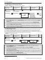
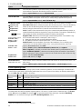
4.3 Connecting Wired Zone and Special Siren
If an expander module is not used, one wired zone and one low voltage siren can be connected directly to the front
panel PCB.
WIRED ZONE
1
&SIREN WIRING
A. GND
B. Wired Zone
C. Siren
D. Site external siren MG electronics MG441PDS or
equivalent 6-12VDC, 150 mA Max
E. Magnetic contact or any other contact (not a
detector)
F. Alarm N.C.
Figure 4.3 – Wired Zone and Siren Wiring
4.4 System Planning & Programming
Program the system now as instructed in the programming section.
The tables in APPENDIX C will help you plan and record the location of each detector, the holder and assignment of
each transmitter.
1
Wired zones can be enrolled in any zone in the PowerMaster-30 G2 control panel from 01 to 64

4. PowerMaster-30 G2 INSTALLATION
D-303222 PowerMaster-10/30 G2 Installer's Guide 19
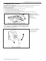
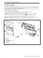
4.5 GSM Module Installation
Plug in the GSM module and fasten it as shown in the above
drawing.
A. GSM
B. Front unit
Caution! Do not install or remove the GSM module when the
system is powered by AC power or backup battery.
Insert the SIM card into the GSM module as shown in
the above drawing.
1. Slide top cover.
2. Open cover
3. Align SIM card in cover (note cover orientation)
4. Slide SIM card into cover
5. Rotate cover to close
6. Lock cover to close
IMPORTANT! Do not insert or remove SIM card when
the control panel is powered by AC power or battery.
Figure 4.5
– Optional GSM Module Mounting and SIM Card Insertion
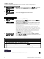
Page is loading ...
Page is loading ...
Page is loading ...
Page is loading ...
Page is loading ...
Page is loading ...
Page is loading ...
Page is loading ...
Page is loading ...
Page is loading ...
Page is loading ...
Page is loading ...
Page is loading ...
Page is loading ...
Page is loading ...
Page is loading ...
Page is loading ...
Page is loading ...
Page is loading ...
Page is loading ...
Page is loading ...
Page is loading ...
Page is loading ...
Page is loading ...
Page is loading ...
Page is loading ...
Page is loading ...
Page is loading ...
Page is loading ...
Page is loading ...
Page is loading ...
Page is loading ...
Page is loading ...
Page is loading ...
Page is loading ...
Page is loading ...
Page is loading ...
Page is loading ...
Page is loading ...
Page is loading ...
Page is loading ...
Page is loading ...
Page is loading ...
Page is loading ...
Page is loading ...
Page is loading ...
Page is loading ...
Page is loading ...
Page is loading ...
Page is loading ...
Page is loading ...
Page is loading ...
Page is loading ...
Page is loading ...
Page is loading ...
Page is loading ...
Page is loading ...
Page is loading ...
Page is loading ...
Page is loading ...
Page is loading ...
Page is loading ...
Page is loading ...
Page is loading ...
-
 1
1
-
 2
2
-
 3
3
-
 4
4
-
 5
5
-
 6
6
-
 7
7
-
 8
8
-
 9
9
-
 10
10
-
 11
11
-
 12
12
-
 13
13
-
 14
14
-
 15
15
-
 16
16
-
 17
17
-
 18
18
-
 19
19
-
 20
20
-
 21
21
-
 22
22
-
 23
23
-
 24
24
-
 25
25
-
 26
26
-
 27
27
-
 28
28
-
 29
29
-
 30
30
-
 31
31
-
 32
32
-
 33
33
-
 34
34
-
 35
35
-
 36
36
-
 37
37
-
 38
38
-
 39
39
-
 40
40
-
 41
41
-
 42
42
-
 43
43
-
 44
44
-
 45
45
-
 46
46
-
 47
47
-
 48
48
-
 49
49
-
 50
50
-
 51
51
-
 52
52
-
 53
53
-
 54
54
-
 55
55
-
 56
56
-
 57
57
-
 58
58
-
 59
59
-
 60
60
-
 61
61
-
 62
62
-
 63
63
-
 64
64
-
 65
65
-
 66
66
-
 67
67
-
 68
68
-
 69
69
-
 70
70
-
 71
71
-
 72
72
-
 73
73
-
 74
74
-
 75
75
-
 76
76
-
 77
77
-
 78
78
-
 79
79
-
 80
80
-
 81
81
-
 82
82
-
 83
83
-
 84
84


Visonic POWERMASTER-10 Installer's Manual
- Category
- Security access control systems
- Type
- Installer's Manual
- This manual is also suitable for
Ask a question and I''ll find the answer in the document
Finding information in a document is now easier with AI
Related papers
-
Visonic PowerMaster-10-30 G2 Version 18 Owner's manual
-
Visonic POWERMASTER-10 - INSTALLER GUIDE User manual
-
Visonic POWERMASTER-10 Installer's Manual
-
-
-
-
-
Visonic POWERMAXEXPRESS - Quick Reference Manual
-
-
Visonic PowerMax Express Owner's manual
Other documents
-
Mace 80355 User manual
-
Mercury DB297 User manual
-
Honeywell EKZ008200B User manual
-
Munters AA18 Owner's manual
-
 Vivint Go!Control User manual
-
 Vivint Go!Control User manual
-
König SEC-APW10 Datasheet
-
 Gardsman CTC-1131 Installation, Programming, Operating
-
Climax Technology GX92752 User manual
-
 CADDX NX-448E-I Installation Instructions Manual


