Page is loading ...

PARTS LIST:
1
Grille Guard
2
10-1.5mm Nylon Lock Nuts
1
Driver/Left Frame Mounting Bracket
4
12mm Plastic Washers
1
Passenger/Right Frame Mounting Bracket
2
12mm Double Nut Plates
1
Driver/Left Top Bracket
2
12mm x 35mm Bolt Plates
1
Passenger/Right Top Bracket
10
12-1.75mm x 35mm Hex Bolts
1
Driver/Left Top Support Bracket
2
12mm ID x 42mm x 42mm x 5.75mm Square
Washers
1
Passenger/Right Top Support Bracket
14
12mm x 32mm OD x 3mm Flat Washers
1
Driver/Left Top Support Brace
12
12mm Lock Washers
1
Passenger/Right Top Support Brace
2
12mm Hex Nuts
1
50mm x 75mm x 1.0mm Adhesive Foam Tape
1
Support flange
2
10mm Quick Release Bolts
2
8mm Nut clips
2
10mm Special Pivot Washers
2
8mm hex bolts
4
10mm Plastic Washers
2
8mm Flat washers
4
10mm x 27mm x 3mm Flat Washers
2
4
8mm Lock washers
M12 - 1.75 Nylon Lock Nuts
Passenger/Right Frame
Mounting Bracket
(2) 12mm Double Nut Plates
Driver/Left Side Frame
Mounting Bracket
Driver/Left
Top Bracket
Passenger/Right
Top Bracket
Driver/Left Top
Support Bracket
Passenger/Right Top
Support Bracket
12mm x 35mm
Bolt Plate
(2) 10mm Quick Release Bolts
(2) 10mm Special Pivot Washers
(2) 12mm ID x 40mm x 40mm x 5mm
Square Washers
Passenger/Right
Top Support Brace
Driver/Left Top
Support Brace
50mm x 75mm x 1.0mm
Adhesive Foam Tape
12mm x 35mm Bolt Plate
Support Flange
(2) 8mm Nut Clips
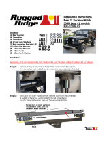
INSTALLATION INSTRUCTIONS
FORD F-150 2WD & 4WD
RETAINS FACTORY TOW HOOKS
PART #P3063
Page 1 of 9 10/14/2015

PROCEDURE:
REMOVE CONTENTS FROM BOX. VERIFY ALL PARTS ARE PRESENT. READ INSTRUCTIONS
CAREFULLY BEFORE STARTING INSTALLATION. ASSISTANCE IS RECOMMENDED. CUTTING IS
REQUIRED ON VEHICLES WITHOUT TOW HOOKS. LICENSE PLATE MUST BE RELOCATED ON
VEHICLES EQUIPPED WITH ECOBOOST.
WARNING! This Grille Guard is designed to tilt forward to open the hood for service. The Top Bracket
Quick Release Bolts and the upper bolts on the Frame Mounting Brackets will need to be loosened slightly
to rotate the Grille Guard. Make sure that all hardware is fully tightened after closing the hood before
moving vehicle. Please read Page 8, "Opening and Closing of Hood," before installing the Grille Guard.
NOTE: It may be necessary to remove/relocate the front license plate and license plate bracket. It is not
required, but strongly recommended. If local/state law requires a license plate, a license plate relocation kit
is available.
1. Start by Selecting your LED light (Sold Separately) mounting hardware & brackets, you will need to first
attached the hardware to the support flange, (Example of LED light attached Fig 1) NOTE: if you have
your own LED light, LED Manufactures will have similar but different mounting styles or brackets,
once you determine you mounting options attach it to the support flange as seen in (Fig1)
2. With the LED light attached to the support flange select the (2) 8mm nut clips place each nut clip into
the slotted holes on either side of the support flange, as seen in (Fig 2) with the support flange prepare
you will need to lay the grill guard face down to install the support flange NOTE: (it is recommended to
lay out some of the cardboard your grill guard came in or a blanket to protect the grill guard finish).
place the grill guard face down with this done place the support flange with the LED attached into the
Center flange attach each side of the support flange to the inner brackets inside the center flange of the
grill guard with (2) 8mm hex bolts, (2) 8mm flat washers, & (2) 8mm lock washers as seen in (Fig 3)
Snug but do not tighten at this time.
3. Determine if the vehicle is or is not equipped with factory tow hooks.
Installation on vehicles with Factory Tow Hooks:
a. Remove the driver side tow hook, (Fig 4).
b. Starting with the driver/Left side Begin your install by removing the factory tow hooks on the
vehicle. (Do not discard as these will be re-attached). The tow hooks are located just under
the front bumper, and are attached to the lower front of frame rails with two bolts attaching to a
nut plate inside the frame rail, (by removing the front mounting bolt and only loosen the
rear bolt you will be able to control the nut plate from moving) with tow hook removed,
place the driver/Left side frame mounting bracket up to the bottom of the frame with the tow
hook. Insert the Front factory bolt through the tow hook, and mounting bracket, securing them to
nut plate hand tighten. Now remove the rear bolt. so you can slide the mounting bracket and tow
hook over, reattach rear bolt threw the tow hook and mounting bracket then back into the nut
plate. (Fig 4A) shown are bracket & tow hook attached. Snug, but do not tighten hardware at
this time. Repeat this step for the Passenger/right side installation
Installation on vehicles without Tow Hooks:
a. Remove the lower plastic portion of the bumper and air dam, (Fig 7).
b. Insert (1) 12mm Double Nut Plate through the opening in the front end of the driver side of the
frame, (Figs 8A & 8B). Line up the threaded holes with the holes in the bottom of the frame.
c. Insert (1) 12mm x 35mm Hex Bolt, (1) 12mm Lock Washer and (1) 12mm Square Spacer into
the rear hole in the bottom of the frame and up into the Double Nut Plate, (Figs 5A & 5B).
Leave completely loose. Select the driver side Frame Mounting Bracket. Slide the slotted end of
the Bracket under the Hex Bolt and Square Washer, (Fig 6). Insert (1) 12mm x 35mm Hex Bolt,
(1) 12mm Lock Washer and (1) 12mm Flat Washer into the empty remaining forward hole in the
Bracket and Nut Plate. Snug but do not tighten the hardware at this time.
d. Repeat Steps a – c for passenger side Frame Mounting Bracket installation.
e. Do not reinstall the plastic lower bumper cover at this time, (See Steps 14a & 14b).
Page 2 of 9 11/12/2013

4. Open the front hood on the vehicle. Locate the top of the bumper bracket behind the driver side of the
front bumper. Locate the open hole in the top outer end of the bumper bracket, (Fig 9). Insert (1)
12mm x 35mm Bolt Plate down and into the gap at the top of the bracket and out through the hole with
the threaded end of the Bolt Plate facing to the rear toward the radiator, (Figs 10A & 10B). Slide the
lower end of the driver side Top Support Bracket, (end with hole), over the Bolt P
late. Secure the
Bracket to the Bolt Plate with (1) 12mm Flat Washer, (1) 12mm Lock Washer and (1) 12mm Hex Nut,
(Fig 11). IMPORTANT: Do not tighten hardware at this time.
NOTE: Before proceeding, cover the top of the plastic bumper, (driver and passenger sides), with
removable tape, (masking tape for example), to protect the bumper during Top Bracket installation, (Fig
11). Next, apply a section of the included Adhesive Backed Foam Tape to t
he bottom of both Top Brackets
to prevent damage to the painted finish on the vehicle, (Fig 13).
5. Select the driver side Top Support Brace, (Fig 12A). Remove the factory hex bolt in the radiator mount.
Bolt the Support Brace in place with the factory hex bolt, (Fig 12B). Leave loose at this time.
6. Select the driver side Top Bracket. Insert the Top Bracket between the Support Bracket and the Rear
Brace, (Fig 13). Line up the (3) holes and bolt the B
rackets together with (1) 12mm x 35mm Hex Bolt,
(1) 12mm Lock Washer and (1) 12mm Flat Washer, (Fig 12B). IMPORTANT: Do not tighten hardware
at this time.
NOTE: It may be necessary to raise or lower the height of the Top Bracket to fit properly between the grille
and the top of the bumper. Loosen the 12mm Hex Nut attaching the bottom of the Support Bracket to the
Bolt Plate, (Fig 11). Move the Top Bracket up or down as needed to clear the top of the bu
mper and line up
with the Grille Guard before tightening the hardware. Do not fully tighten Top Bracket hardware until after
all hardware has been installed and the Grill Guard properly aligned and adjusted.
7. Repeat Steps 4 – 6 for passenger side Top Bracket, Support Bracket and Top Brace installation.
8. With assistance, place the Grille Guard face down on a clean surface in front of the vehicle, (Fig14).
Position the mounting tabs on the Grille Guard up to the outside of the Frame Mounting B
rackets.
9. Line up the rear hole in the driver side Frame Mounting Bracket with the hole in the Grille Guard, (Fig
15). Insert (1) 12mm Plastic Washer between the Mounting Bracket and the Grille Guard. Bolt the Grille
Guard to the driver side Bracket with (1) 12mm x 35mm Hex Bolt, (2) 12mm Flat Washers, & (1) 12mm
Nylon Lock Nut (Fig 15). Snug but do not tighten hardware at this time.
10. Repeat Step 9 to attach the Grill Guard to the passenger side Bracket.
11. Use the two previously install
ed Hex Bolts as a hinge. Rotate the Grille Guard up to the vehicle, (Fig
14). Line up the remaining hole in each Bracket with the Grille Guard. Insert a 12mm Plastic Washer
between the Mounting Bracket and the Grille Guard on both sides of the vehicle as described in Step 9.
Bolt the Grille Guard to the Brackets with (2) 12mm x 35mm Hex Bolts, (4) 12mm Flat Washers and
(2) 12mm Nylon Lock Nuts. Do not tighten hardware at this time.
12. Next, line up the slotted end of the driver side To
p Bracket with the hole in the Grille Guard upright.
Insert (1) 10mm Plastic Washer between the Top Bracket and the Grille Guard, (Fig 16). Line up the
hole in the Plastic Washer with the hole in the Grille Guard and the slot in the Top Bracket. Insert (1)
10mm Quick Release Bolt, (1) 10mm Special Pivot Washer and (1) 10mm Flat Washer through the
upright on the Grille Guard first and on through the Plastic Washer and Top Bracket. Secure the Quick
Release Bolt with
(1) 10mm Plastic Washer, (to protect the finish on the Top Bracket), (1) 10mm Flat
Washer and (1) 10mm Nylon Lock Nut, (Figs 17A & 17B). Do not tighten hardware at this time.
13. Repeat Step 12 for the passenger side Quick Release installation.
14. With the hood open, push the Grille Guard back until it is vertical. Align, center and adjust the Grille
Guard properly and tighten all Mounting Bracket and Support Bracket hardware.
Vehicles without tow hooks:
Page 3 of 9 11/12/2013

a. Once the Frame Brackets are fully tightened to the vehicle, temporarily remove only the Grille
Guard. Hold the plastic lower bumper cover up in the approximate position against the bottom
Of the bumper and against the Brackets, (If cover was previously removed in Step 3a). Mark the
Bracket location onto the back of the bumper cover. Cut slots through the cover to clear the
Brackets, (Fig 18). IMPORTANT: For best results, start with a small opening and only trim away
material required for Bracket clearance. Once properly trimmed, reinstall plastic bumper cover
with the factory hardware.
b. Reinstall the Grille Guard and tighten all Mounting Bracket and Support Bracket hardware.
15. Release the levers on the Quick Release Bolts, (Fig 19), and loosen the top Hex Bolts on the Frame
Mounting Bracket. WARNING! Do not loosen the bolts all the way. Loosen hardware only enough to
move the Grille Guard. Damage to the truck or Grille Guard may occur.
16. Pull the Grille Guard all the way forward, away from the vehicle, (Fig 20).
17. Carefully close the hood and check for clearance between the Top Bracket and the factory grille. Adjust
the Brackets up or down for fit as necessary. IMPORTANT: Always make sure that the hood and grille
will clear the Grille Guard before closing the hood.
18. Close the hood. Push the Grille Guard back towards the vehicle until it is vertical, check the alignment
again and adjust the Grille Guard as required. Tighten all Mounting Bracket hardware including the
Quick Release Bolts, (Fig 19).
19. Do periodic inspections to the installation to make sure that all hardware is secure and tight,
For the Led lights wiring please refer to the manufactures installation.
Fig 1
LED light attached to support flange.
NOTE:
LED Manufactures will have similar
but different mounting styles or brackets,
once you determine you mounting options
attach it to the support flange as seen.
8mm nut clip
attached (1) per side
Fig 2
Support flange
Secure support flange into center flange with
(1) 8mm Hex head bolt
(1) 8mm Flat Washers
(1) 8mm Lock washer
Per side.
Fig 3
Led Light
Page 4 of 9 11/12/2013

Driver Side Installation Pictured
Fig 6
Front
Remove tow hooks
if equipped
(Fig 7) Example of lower bumper
cover on vehicles without tow hooks
Front
(Fig 4) Driver side w/tow hook
Rear location:
12mm x 35mm Hex Bolt
12mm Lock Washer
12mm Square Washer
Fig 5A
Fig 5B
Front
Front
12mm x 35mm Hex Bolt
12mm Lock Washer
12mm Flat Washer
(Fig 4A)
Page 5 of 9 11/12/2013

Driver Side Installation Pictured
Fig 11
(Fig 10B) Driver side pictured from behind bumper
Front
(Fig 8B) Insert Nut Plate through opening
in end of frame (NOTE: Tow hook model
pictured for instruction purposes only)
Insert 12mm Bolt Plate through
outermost hole in bumper bracket
12mm Bolt Plate
12mm Lock Washer
12mm Flat Washer
12mm Hex Nut
Front
Fig 8A
Front
Driver side frame
channel
(Fig 10A) 12mm
x 35mm Bolt
(Fig 9) driver side pictured
Opening in center of bumper
Cover a section (dotted line) of the top of the
bumper with removable tape to prevent
damage to finish on bumper
Loosen Hex Nut on Bolt Plate (Fig 8) and adjust
height of Support Bracket (up or down) as
necessary. Do not tighten Hex Nut until final
adjustment step.
Front
Page 6 of 9 11/12/2013

Driver Side Installation Pictured
Fig 13
12mm x 35mm Hex Bolt
12mm Lock Washer
12mm Flat Washer
Protect the top of the plastic bumper
cover with masking tape to prevent
scratches during installation
For easier installation, insert (1) 12mm Hex Bolt,
(2) 12mm flat washers on each side and secure
with (1) 12mm nylock nut in location shown in
Figure 8 to act as a hinge.
Insert 12mm Plastic Washers between the Grille
Guard and the Mounting Bracket. Line up the holes in
the Plastic Washers with the mounting holes. Insert
the Mounting Bolts through the Plastic Washers
Fig 14
(2) 12mm x 35mm Hex bolts
(4) 12mm Flat Washers
(2) 12mm Nylock nuts
Front
Fig 12B
Fig 15
Front
Front
Use factory hex bolt
Cover a section (dotted line) of the
bottom of the Bracket with Foam Tape
to prevent damage to finish on bumper
Fig 12A
Snug the hardware
but do not tighten,
then rotate the Grille
Guard up into
position
Page 7 of 9 11/12/2013

Driver Side Installation Pictured
Fig 16
Insert a 10mm Plastic Washer between the
Grille Guard and the slotted Top Bracket.
Line up the hole in the Plastic Washer with
the mounting holes. Insert the Quick
Release Bolt through the Plastic Washers
Front
Place a 10mm Plastic Washer
between the slotted Top Bracket and
the 10mm Flat Washer to protect the
finish on the Top Support Bracket.
Inside of upright on Grille Guard
pictured
Fig 17B
Front
Non tow hook model pictured. Once Grille Guard has been
completely installed and lined up properly on the vehicle, tighten
only the hardware bolting the Frame Brackets to the frame. Remove
the Grille Guard. Hold the plastic lower bumper cover up in the
original position against the Brackets. Trace the Frame Bracket
locations onto the cover. Cut out the area with sharp knife of
hacksaw blade. Cut as little as possible from cover. Do not cut
through top or bottom edge. Cut area pictured for example only.
Installer responsible for correct modifications
Fig 17A
Fig 18
Do not cut through
top or bottom edge
of bumper cover
Front
Special 10mm
Pivot Washer
Page 8 of 9 11/12/2013

Driver Side Installation Pictured
Opening and closing the hood
1. Lift the levers on the two Quick Release Bolts to release clamping pressure, (Fig 19). Try to pull the
Grill Guard forward. If necessary, slightly loosen the top hex bolts on the Frame Mounting Brackets to
pivot the Grille Guard away from the vehicle. Carefully pull on the Grille Guard until it is fully extended
away from the vehicle, (Fig 20). WARNING! Do not loosen the bolts all the way. Damage to the truck or
Grille Guard may occur. Only loosen the bolts enough to move the Grille Guard.
2. Pull the hood release and open the hood.
3. IMPORTANT: Before closing the hood, always check to make sure that the Grille Guard hasn’t been
pushed back to its "closed" position and that it is fully extended away from the vehicle, then close the
hood.
4. Once the hood is completely closed, push the Grille Guard back to its closed, upright position and
tighten all hardware on the Grille Guard. Push down on the Quick Release lever to tighten, (Fig 19). No
tools are required to close the Quick Release levers. It will require some effort to open and close by
hand when properly adjusted. Loosen or tighten the 10mm Nylon Lock Nut on the Quick Release bolt to
adjust the clamping pressure.
5. Do periodic inspections to the installation to make sure that all hardware is secure and tight.
To protect your investment, wax this product after installing. Regular waxing is recommended to add a
protective layer over the finish. Do not use any type of polish or wax that may contain abrasives that could
damage the finish.
Fig 20
Fig 19
Tighten or loosen the 10mm Nylon Lock
Nut to adjust the clamping pressure on the
Quick Release Bolt. When properly
adjusted, it should require reasonable force
(by hand only) to completely close the lever
To open the hood, release the lever on
the Quick Release Bolts. Try to pull
the Grille Guard forward. If necessary,
loosen the Hex Bolts securing the
Grille Guard to the Mounting Brackets.
Only loosen the hardware enough to
move the Grille Guard
Close
Open
Front
Complete Install
Page 9 of 9 11/12/2013
/