Page is loading ...

REMOTE STARTER, UNIVERSAL ALL-IN-ONE DATA BYPASS AND
INTERFACE MODULE�
DÉMARREUR À DISTANCE, MODULE DE CONTOURNEMENT EN
DATA UNIVERSELLE TOUT-EN-UN ET INTERFACE�
COMPLETE INSTALL GUIDE
Rev : 20200304
Guide # 94011
Page 1 / 28

Page 3 / 4
Page 2 / 28
TABLE DES MATIÈRES
NOTICE: ������������������������������������������������������������������������������������������3
WARNING: �������������������������������������������������������������������������������������3
INTRODUCTION ��������������������������������������������������������������������������3
PART LIST ���������������������������������������������������������������������������������������3
INSTALLATION POINTS TO REMEMBER ������������������������4
HARNESS DESCRIPTIONS ����������������������������������������������������6
6 PIN IGNITION HARNESS �����������������������������������������������������6
20 PIN SECONDARY HARNESS ������������������������������������������8
BEFORE PROGRAMMING ����������������������������������������������������10
FORTIN RF-KIT TRANSMITTER PROGRAMMING
PROCEDURE* �����������������������������������������������������������������������������10
ERASE ALL REMOTES ���������������������������������������������������������� 11
PROGRAMMING PROCEDURE �����������������������������������������11
PROGRAMMING GUIDE ��������������������������������������������������������12
Not applicable (option #1) �����������������������������������������������������������12
Programmable Output (+) Ign/Acc/Start/Park-Light (option #2) ��12
Tachless sensivity (option #3) ������������������������������������������������������12
Remote car starter runtime (option #4) ����������������������������������������12
Not applicable (option #5) �����������������������������������������������������������13
Door Lock before and after remote-start (option #6) �������������������� 13
Safety Locks (option #7) ��������������������������������������������������������������13
Unlock Pulse Time (option #8) �����������������������������������������������������13
Active or Passive Alarm & Starter Kill (option #9) ������������������������14
Starter Kill Output (option #10) ����������������������������������������������������14
Conrmation option #11) �������������������������������������������������������������14
Conrmation sound (option #12) ������������������������������������������������� 14
Conrmation time (option #13) ���������������������������������������������������� 15
Alarm & Starter Options (option #14) �����������������������������������������15
Smart Door lock relocking and alarm rearming (option #15) �������15
Cold Starter Timer (option #16) ���������������������������������������������������15
Not applicable (option #17) ���������������������������������������������������������15
Diesel mode (option #18) ������������������������������������������������������������15
Turbo mode (option #19) ������������������������������������������������������������� 16
Engine supervision: Tachless , analog tach or Tach Data-Link
(option #20) ����������������������������������������������������������������������������������16
start attempts (option #21) ����������������������������������������������������������16
Transmitter Start/Stop function* (option #22) ������������������������������16
reset (option #23) ������������������������������������������������������������������������16
Not applicable (option #24) ���������������������������������������������������������16
Auxiliary 1 (option #25) ���������������������������������������������������������������16
Hybrid (option #26) ����������������������������������������������������������������������17
Not applicable (option #27) ���������������������������������������������������������17
Alarm duration (option #28) ���������������������������������������������������������17
valet code (option #30) ����������������������������������������������������������������17
Valet coding disable (Default): �����������������������������������������������������17
Valet coding enable: ��������������������������������������������������������������������� 17
Special application Programmable output (+) (option #31) ���������18
DK�BLEU WIRE (A8) CONFIGURATION (option #32) ���������������18
Ready modeactivation for manual transmission (option #33) �����18
Trunk output (option #34) ������������������������������������������������������������21
Door unlock Special application (option #35) ������������������������������ 21
VALET MODE ACTIVATION/DEACTIVATION (option #36) ��������21
Security Remote car starter Special application (option #37) �����21
System control by OEM Remote (option #38) �����������������������������22
Temperature option (option #39) �������������������������������������������������22
Door locks*���������������������������������������������������������������������������������������������������������������������������������������������������22
Trunk or hatch release* ����������������������������������������������������������������22
Key bypass* ��������������������������������������������������������������������������������������������������������������������������������������22
Heated Seats (Rear defrost)*�����������������������������������������������������������������������������������������22
Aux� 1* ����������������������������������������������������������������������������������������������������������������������������������������������������22
Aux� 2* ���������������������������������������������������������������������������������������������������������������������������������������������������22
Foot-Brake* ��������������������������������������������������������������������������������������������������������������������������������������22
Hand-Brake* ������������������������������������������������������������������������������������������������������������������������������������22
Door Trigger* �����������������������������������������������������������������������������������������������������������������������������������22
Trunk Trigger* ��������������������������������������������������������������������������������������������������������������������������������22
Hood Trigger* ���������������������������������������������������������������������������������������������������������������������������������23
Unlock before trunk release* ������������������������������������������������������������������������������������������23
ignition lock* �������������������������������������������������������������������������������������������������������������������������������������23
Parking lights control* ������������������������������������������������������������������������������������������������������������23
Unlock driver door priority* �����������������������������������������������������������������������������������������������23
Unlock double pulse* �������������������������������������������������������������������������������������������������������������23
Unlock before/Lock after* ���������������������������������������������������������������������������������������������������23
Shutdown on door opening* ��������������������������������������������������������������������������������������������23
Hybrid Mode* �����������������������������������������������������������������������������������������������������������������������������������23
Lock after start* �����������������������������������������������������������������������������������������������������������������������������23
Push-To-Start* ������������������������������������������������������������������������24
RAP* ��������������������������������������������������������������������������������������24
Special functions �������������������������������������������������������������������� 24
Datalink protocol ��������������������������������������������������������������������24
EVO-ALARM ��������������������������������������������������������������������������24
Supported rf kits ���������������������������������������������������������������������24
ARMING THE SYSTEM WITHOUT RF KIT ������������� 24
DISARMING THE SYSTEM WITHOUT RF KIT ������24
ENTERING VALET MODE WITHOUT RF KIT ��������24
EXITING VALET MODE WITHOUT RF KIT ������������� 25
ENABLING COLD START MODE ���������������������������������26
DISABLING COLD START MODE ��������������������������������26
REMOTE START / ALARM DIAGNOSTICS ��������������26
REMOTE STARTER DIAGNOSTICS ���������������������������26
ALARM DIAGNOSTICS ����������������������������������������������������� 26
INSTALLATION VERIFICATION ������������������������������������ 27
CLOSING UP �������������������������������������������������������������������������27
LIABILITY �������������������������������������������������������������������������������27
WARNING �������������������������������������������������������������������������������� 27

Page 3 / 4
Page 3 / 28
NOTICE:
The manufacturer will accept no responsibility for any electrical damage resulting from improper installation of the
product, including either damage to the vehicle itself or to the remote-starter module. This module must be installed by
a certified technician including all of the supplied safety devices. Please note that this guide has been written for trained
professional technicians, a certain level of skills and knowledge is therefore assumed. Please review the Installation Guide
carefully before beginning any work.
WARNING:
By default this system is setup for vehicles with a manual transmission. For vehicles with an automatic transmission the
safety wire loop on the main unit must be cut. Before proceeding to the installation, make sure that the vehicle does not
attempt to start when the when the vehicle is in the “drive” or “reverse” position. If an automatic transmission vehicle
starts when the transmission is in gear, ensure that the safety wire loop on the unit is not cut. Once the safety wire loop is
cut, the system is considered an automatic transmission remote-starter indefinitely. Once a loop is cut it should never be
reconnected, if so, all warranties, guaranties, and liability is immediately void.
WARNING !
DCBHIJCUT LOOP FOR
AUTOMATIC
TRANSMISSION
MODE�
MANUAL MODE:
DO NOT cut the loop for a Manual transmission vehicle, this
will void all guarantees and warranties.
automatic MODE:
Cut the loop for an Automatic transmission vehicle.
INTRODUCTION
This guide contains all the information relevant and necessary for the installation of the module. Most of the features
of this product are explained in the User Guide. Therefore, if detailed information regarding a feature of the product is
needed, refer to the User Guide.
PART LIST
Please carefully read the installation guide before beginning the installation, especially the harness descriptions and the
programming options. It is very important that the programming and the operation of the module are clearly understood,
even with similar installation experience in the past. There are many innovative features that may be overlooked if this
guide is not read thoroughly. Prior to the installation, make sure that all the hardware components required to install the
system are included in the box.
The following is a list of components included in the kit:
•1x Remote-Starter control unit
•1x or 2x Transmitters (only on combo kit)
•1x Antenna (only on combo kit)
•1x Hood switch
•1x 6 pin primary ignition harness (AWG 14)
•1x 20 pin secondary harness (AWG 22)
•1x 5 pin CAN harness
•1x 6 pin harness (red)
•1x warning label
•1x User guide (only on combo kit)
•1x Quick Installation guide

Page 3 / 4
Page 4 / 28
INDUSTRY CANADA USER NOTICE:
Operation is subject to the following two conditions: (1) this device may not cause interference, and (2) this
device must accept any interference, including interference that may cause undesired operation of the device�
To reduce potential radio interference to other users, the antenna type and its gain should be so chosen that the
equivalent isotropically radiated power (EIRP) is not more than that required for successful communication�
FCC – USER NOTICE:
The manufacturer is not responsible for any radio or TV interference caused by unauthorized modications to
this equipment. Such modications could void the user’s authority to operate the equipment.
INSTALLATION POINTS TO REMEMBER
•Make sure that vehicles equipped with an Automatic transmission can not start while in any gear other than park. If
the vehicle starts in gear, a Manual transmission Remote-Starter must be installed.
•When installing a Manual transmission Remote-Starter on a vehicle with a Manual transmission, always make sure
that all doors will take the Remote-Starter out of Ready Mode. If this is not the case switch the wire(s) so that the
module can monitor all doors (including the rear hatch).
•When installing a Manual transmission Remote-Starter on a vehicle with a Manual transmission, ensure that the park-
ing brake and all door switch contacts are working properly.
•When working on a vehicle, never leave the keys inside the vehicle and always leave at least one window open.
•If possible, remove the courtesy light fuse to prevent battery drain.
•Before beginning, inspect the vehicle for any body damage or electrical problems.
•It recommended to solder all connections.
•All connections must be isolate with electrical tape.
•Keep the Antenna away from other types of antennas (GPS/OnStar).
•Never install the module or wiring where it could interfere with the mechanical operation of the steering and pedals or
obstruct service technicians.
•Always use a grommet when running wires into the engine compartment. Never run wires near or against bare metal.
•Never ground the module to the vehicle’s steering column.
•Make sure that all the switches and controls operate properly.
•Verify that the vehicle starts and idles properly (optionnal).
•Make sure that all safety equipment is installed: the Valet switch, Hood Pin switch and warning label(s).
•Always make sure that all external relays and after-market products wired to the module are properly fused and diode
isolated.
•On vehicles equipped with daytime running lights, the installer may be unable to see certain programming results
since the daytime running lights never go out. (Note : Listening carefully to the clicking of the relays within the mod-
ule will indicate a selected option. A test light on the positive park light output may also be used for a visual indicia-
tion)
•When wiring in parallel, make sure each connection is isolated with a diode in order to avoid feedback and possible
damage to the vehicle.
Examples :
1-Wiring both a clutch bypass and a transponder bypass module to the GROUND OUT WHEN RUNNING
wire: At the common connection point, where the GROUND OUT WHEN RUNNING wire “splits” and con-
nects to both devices, a diode should be inserted on both wires to prevent feedback.
2-Multiple or separate door pin connections: When joining all Door Pins together to the single input wire of
the module, each of the door wires must be diode isolated to prevent feedback.
NOTE: The above examples reflect common situations where diodes are use to isolate connections. Please
note that there are numerous other cases where diode isolation may be required.

Page 3 / 4
Page 5 / 28

Page 3 / 4
Page 6 / 28
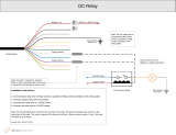
HARNESS DESCRIPTIONS
6 PIN IGNITION HARNESS
When first connecting the system it is important to connect the primary 6 pin harness (containing the ground wire) first,
otherwise the internal components of the module could be seriously damaged.
Be careful not to power up a module before it is properly grounded (Pin 4).
Ground Black IN
(+) IgnitionPink OUT
(+) Starter Yellow OUT
OUT White (+) PARKLIGHTS/IGN2/ACC/START
PROGRAMMABLE OUTPUT (FUNCTION 2 & 31)
OUT Orange (+) ACC / IGN2
PROGRAMMABLE OUTPUT (FUNCTION 2 & 31)
IN Red (+) 12V
(6-PIN) POWER CONNECTOR
E6
E5
E4 E1
E2
E3
FILAGE / GUIDE DE BRANCHEMENTS
There is one power wire acting as a module input, while the remaining wires are outputs that reproduce the electronic
actions of the vehicle’s ignition switch when Remote-Started. These wires are usually connected at the ignition switch.
DO NOT MODIFY THE INTEGRITY OF THE VEHICLE BY JUMPING ANY WIRES, THIS WILL COMPROMISE THE
OEM ELECTRICAL SYSTEM�
WIRE COLOUR FUNCTION DESCRIPTION
E1
WHITE
Programmable
OUTPUT
FUNCTION 2 AND
FUNCTION 32
(+) PARKING
LIGHT OUTPUT This wire is a high current programmable output that can either
provide a 2nd Ignition, 2nd Accessory, 2nd Starter or Parking light
output. See the pro gramming guide (Function 2 or 31) to program
the module for the desired output.
(+) 2ND IGNITION
(+) 2ND ACCES-
SORY
(+) 2ND STARTER
E2
ORANGE
Programmable
OUTPUT
FUNCTION 2 AND
FUNCTION 31
(+) ACCESSORY
OUTPUT (30 A)
Connect to the vehicle’s Accessory wire (blower motor). This wire
must have +12VDC when the key is at the RUN postion, but not at
the CRANK position.
WARNING ! Some vehicles may have more than one Accessory
wire. If necessary use the 5th relay (pin 1) and an extra relay(s) to
power up each extra Accessory wire(s)
This wire can be programmed either as an ACCESSORY or IGNI-
TION wire with Function 2 or 31.
(+) IGNITION2
OUTPUT (30 A)
This wire is a high current output that can provide a 2nd Ignition.
See the programming guide (option 2) to program the module for
the desired output.

Page 3 / 4
Page 7 / 28
WIRE COLOUR FUNCTION DESCRIPTION
E3 RED (+) BATTERY
12V
Connect to the vehicle’s constant +12VDC power wire. Ensure that
the vehicle’s power wire is fused at more than 30A.
Note : Some modern vehicles do not have a suitable +12VDC
source at the Ignition switch (the wires are too small to supply
enough current). In such cases, this wire must be connected to a
higher current source (maybe even directly at the battery).
E4 BLACK (–) CHASSIS
GROUND INPUT
This wire must be connected to bare, unpainted, non-corroded
metal (on the vehicle chassis). It is preferable to use a factory
ground bolt rather than a self-tapping screw. Screws loosen over
time which cause erratic behaviour.
E5 PINK
(+) IGNITION
OUTPUT/INPUT
(30 A)
Connect to the vehicle’s Ignition wire. This wire must have
+12VDC when the key is at the RUN and CRANK position.
WARNING ! Some vehicles may have more than one ignition
wire. If necessary use the 5th relay (pin 1) and an extra relay(s) to
power up any extra Ignition wire(s).
E6 YELLOW (+) STARTER
OUTPUT
(30 A)
Connect to the vehicle’s Starter wire. This wire must have +12VDC
only when the key is at the CRANK position.
WARNING ! Some vehicle may have more than one Starter
wire. If necessary use the 5th relay (pin 1) and an extra relay(s) to
power up each extra Starter wire(s).

Page 3 / 4
Page 8 / 28
20 PIN SECONDARY HARNESS
A1
A20
(+) Foot Brake Black IN
750mA (-) Parking lights Pink OUT
750mA (-) Trunk Release/AUX Yellow/Black OUT
(-) Hand Brake Brown/White IN
(-) Hood/Door Pink/Black IN
Purple/Yellow
Green/White
Green/Red
White/Black OUT
Lt.Blue
750 mA MAXIMUM OUTPUT. DO NOT EXCEED THE MAXIMUM CURRENT OR PERMANENT DAMAGE TO THE MODULE WILL OCCUR THAT WILL NOT BE COVERED
UNDER WARRANTY.
(20-PIN) SECONDARY CONNECTOR
IN Yellow (+) BYPASS IGNITION
OUT Purple (-) LOCK750mA
OUT Purple/White (-) UNLOCK750mA
OUT Green (-) IGNITION 750mA
OUT White (-) START 750mA
OUT Orange (-) DISARM 750mA
OUT Orange/Black (-) HORN/SIREN 2 Amp
OUT Dk.Blue (-) GWR/PROGRAMMABLE 750mA
IN Red/Blue BYPASS CONFIG.
Lt.Blue/Black BYPASS CONFIG.
WIRE COLOUR FONCTION DESCRIPTION
A1 YELLOW (+) IGNITION
INPUT
Connect to the vehicle’s Ignition wire. This wire must have
+12VDC when the key is at the RUN and CRANK position.
A2 PURPLE (–) LOCK
OUTPUT
This output (400mA) provides a single negative LOCK pulse for
1second.
A3 PURPLE/WHITE (–) UNLOCK
OUTPUT
This output provides a negative unlock pulse (400mA). This pulse
is programmable for either a single 1 second, single 4 second, or
double 1 second pulse(s).
A4 GREEN (–) IGNITION
OUTPUT
Connect to either the negative Ignition wire of the vehicle, or to
an external relay (400mA). The vehicle’s Ignition wire will ground
when the key is in either the RUN or CRANK position.
Warning ! Some vehicles may have more than one Ignition wire.
A5 WHITE (–) STARTER
OUTPUT
Connect to either the negative Starter wire of the vehicle, or to an
external relay (400mA). The Starter wire grounds only when the
key is in the CRANK position.
Warning ! Some vehicles may have more than one Starter wire.
A6 ORANGE (–) DISARM
OUTPUT
This ouput provides a single negative disarm pulse (400mA) for
1 second whenever the doors are unlocked. This signal is sent
10ms before the unlock signal.
Note : A single disarm pulse is also provided before Remote-Start.
A7 ORANGE/BLACK (–) HORN
OUTPUT
This negative ouput (2 Amp) provides a Ground for negative Horn
or a negative siren. Connect to the negative horn wire at the steer-
ing column. A high current relay must be used when connected
directly horn.

Page 3 / 4
Page 9 / 28
WIRE COLOUR FONCTION DESCRIPTION
A8 DK.BLUE
(–) GROUND
OUT WHEN
RUNNING
OUTPUT
This output (400mA) provides a constant ground when the ve-
hicle is Remote-Started. It is activated 1 second before Remote-
Start and deactivated 1 second after shut-down.
CAUTION : If this wire is used to control several relays and/or
modules ensure each output is diode isolated to prevent feedback
which can damage the vehicle.
A9 RED/BLUE Dedicate with bypass configuration. See vehicle installation
guide.
A10 LT.BLUE/BLACK Dedicate with bypass configuration. See vehicle installation
guide.
A11 BLACK (+) BRAKE
SWITCH INPUT
Connect to the either the brake switch or directly to a brake light.
This wire must have +12VDC whenever the brake pedal is par-
tially or fully depressed. It should not have any voltage when the
brake pedal is at rest or when the turn signals are in use. This
wire is mandatory and used during programming. (On vehicles
where the brake signal is not present on the vehicle’s canbus)
A12 PINK (–) PARK LIGHT
OUTPUT
Connect to the vehicle’s negative parking light wire (750mA).
This wire will test as a ground when the parking light switch is
turned on.
A13 YELLOW/BLACK (–) TRUNK
OUTPUT
This output (750mA) should be connected to either the negative
trunk release switch, or control a high current relay that powers
the trunk/hatch solenoid.
A14 BROWN/WHITE
(–) HAND
BRAKE
INPUT
Connect to the vehicle’s negative Parking Brake signal. This wire
can either be found at the parking brake lever or at the cluster’s
indicator light.
Note: The input should be at ground whenever the parking brake
is engaged.
IMPORTANT! Mandatory on Manual transmission vehicles.
A15 PINK/BLACK
(–) HOOD PIN
INPUT
ZONE 5
Connect to the Hood Pin safety switch.
Note: This input should be at ground whenever the hood is
opened to prevent Remote-Starting.
IMPORTANT! Mandatory on all vehicles.
(–) DOOR PIN
INPUT
ZONE 3
This zone should be used in a vehicle equipped with a negative
door pin circuit. This zone triggers the alarm.
warning ! Ensure this wire is grounded whenever any door is
opened. Only connecting the driver’s door is not sufficient.
A16 PURPLE/YELLOW Dedicate with bypass configuration. See vehicle installation
guide.
A17 GREEN/WHITE Dedicate with bypass configuration. See vehicle installation
guide.
A18 GREEN/RED Dedicate with bypass configuration. See vehicle installation
guide.

Page 3 / 4
Page 10 / 28
WIRE COLOUR FONCTION DESCRIPTION
A19 WHITE/BLACK Dedicate with bypass configuration. See vehicle installation
guide.
A20 LT.BLUE Dedicate with bypass configuration. See vehicle installation
guide.
BEFORE PROGRAMMING
The Transmitters included with the module are NOT pre-programmed: they each need to be manually programmed after
installation is complete. The Remote-Starter/Alarm can learn up to a maximum of 4 Transmitters. Once a 5th Transmitter
is programmed the 1st transmitter is erased (FIFO).
FORTIN RF-KIT TRANSMITTER PROGRAMMING PROCEDURE*
Transmitter only included on combo kit.
STEP 1 STEP 2 STEP 3 STEP 4 STEP 5 STEP 6
WITH IGNITION SWITCH
Turn the
Ignition
O F F.
Turn the
Ignition
ON.
The LED
will turn
ON on the
antenna. x4
Press and
release the
brake pedal
four times.
The
LED will
ash
rapidly
on the
an-
tenna.
4 BUTTON REMOTE:
OR
Turn
the
Ignition
ON.
WITH VALET SWITCH*
Press
and hold
the valet
switch*
until the
parking
lights turn
ON, the
horn/siren
will chirp.
x5
Press and release
the valet switch* ve
times.
The parking lights will
ash and the horn/
siren will chirp each
time to conrm.
x1
Press and
release the
brake pedal
once.
4 BUTTON REMOTE:
On each Transmitter press
and release the FUNCTION
or TRUNK button then
press and release the LOCK
button.
1 BUTTON REMOTE:
On each Transmitter
Press and HOLD the for
12SECONDS approximatively and
WAIT for the Blue LED to
TURN OFF then back ON SOLID
then release .
The LED will stop ashing
for a second conrming
programming on the
antenna.
Turn the
Ignition OFF
to exit pro-
gramming.

Page 3 / 4
Page 11 / 28
ERASE ALL REMOTES
Erase all remotes that have been programmed and Resets all functions back to default.
Disarm
the sys-
tem (The
antenna
led must
not be
ash-
ing, see
enter/
exit valet
mode).
STEP 1 STEP 2 STEP 3 STEP 4 STEP 5 STEP 6
Turn
the Ig-
nition
ON.
OR Press
and hold
the valet
switch*
or the
antenna
button
until the
Parking
lights turn
ON, the
horn/siren
will chirp.
OR
Press
and
release
the
valet
switch*
or the
an-
tenna
button
23
TIMES.
X1
Press
and
release
the
brake
pedal
once.
OR Press
and hold
the valet
switch*
or the
antenna
button
for 5 sec-
onds. The
Parking
lights
will ash
to con-
rm.
Turn
the
Ignition
OFF
to exit
pro-
gram-
ming.
The
Parking
lights
will
ash 4
times.
Press
and
hold the
button
on the
antenna
Press and
release
the button
on the
antenna
Press
and
hold the
button
on the
antenna
Within 5 sec.
PROGRAMMING PROCEDURE
Dis-
arm
the
system
(The
anten-
na led
must
not be
ash-
ing,
see
enter/
exit
valet
mode).
STEP 1 STEP 2 STEP 3 STEP 4 STEP 5 STEP 6
OR
Press and hold
the antenna
button The
LED will
ash
rapidly
on the
antenna.
OR
Press and release the
antenna button
X1
ON MOST REMOTE*:
MODE 1 - LOCK
MODE 2 - UNLOCK
MODE 3 - START
MODE 4 - FUNCTION or AUX
MODE 5 - FUNCTION or AUX + LOCK
MODE 6 - FUNCTION or AUX +
UNLOCK
(*THE SEQUENCE CAN VARY DEPENDING ON THE
KIT, SEE EVO-ONE QUICK GUIDE ASSOCIATED
WITH THE REMOTE)
Turn the
Ignition
ON.
Press and hold
the valet switch*
or the antenna
button until the
Parking lights
turn ON, the
horn/siren will
chirp.
*Valet switch
sold separately
Press and release the
valet switch or the
antenna button X time
for the desired function.
The Parking lights will
ash and the horn/siren
will chirp each time to
conrm.
Press and
release
the brake-
pedal
once.
Turn the
Ignition
OFF
to exit
program-
ming.
The Park-
ing lights
will ash
4 times.
Press the BUTTON(S) on a programmed remote to
select the mode (X).
The Parking lights will ash 1-6 times to conrm.
Within 5
sec.
Return to step 3 to program the next option

Page 3 / 4
Page 12 / 28
PROGRAMMING GUIDE
See Quick Install Guide for the latest version of PROGRAM GUIDE.
NOT APPLICABLE (OPTION #1)
Does not apply.
PROGRAMMABLE OUTPUT (+) IGN/ACC/START/PARK-LIGHT (OPTION #2)
Relay configuration, see specific vehicle installation guide.
MODE 1 (Button 1) White (+)Ignition2
Orange (+)Accessory
Pink (+)Ignition
Yellow (+)Start
MODE 2(Button 2) White (+)Accessory2
Orange (+)Accessory
Pink (+)Ignition
Yellow (+)Start
MODE 3 (Button 3) White (+)Start2
Orange (+)Accessory
Pink (+)Ignition
Yellow (+)Start
MODE 4 (Button 4) White (+)Start2
Orange (+)Ignition2
Pink (+)Ignition
Yellow (+)Start
TACHLESS SENSIVITY (OPTION #3)
This programming option adjusts the length of crank time for the Remote-Starter. If the vehicle over-cranks or under-crank,
the crank time can be adjusted. This works with tachless mode (function 20.1 et 20.2).
When reprogramming option 3 (Crank time)
*-Each press of button 1 (LOCK) will gradually increase the length of crank time.
(Required when the vehicle under-cranks)
**-Each press of buttons 3 + 4 (TRUNK, START) simultaneously will gradually decrease the length of crank time. (Re-
quired when the vehicle over-cranks)
Length of time the starter will crank.
MODE 1 (Button 1) Increase crank time
MODE 2(Button 2) +++++
MODE 3 (Button 3) ++++ (by default)
MODE 4 (Button 4) +++
MODE 5 (Button 1 and 2) ++
MODE 6 (Button 3 and 4) Decrease crank time
REMOTE CAR STARTER RUNTIME (OPTION #4)
The Remote-Starter runtime in minutes. (x2) in diesel mode. (See option #18)
MODE 1 (Button 1) Gas: 15 minutes
Diesel: 30 minutes
MODE 2(Button 2) Gas: 7 minutes
Diesel: 14 minutes

Page 3 / 4
Page 13 / 28
MODE 3 (Button 3) Gas: 3 minutes
Diesel: 6 minutes
NOT APPLICABLE (OPTION #5)
Does not apply.
DOOR LOCK BEFORE AND AFTER REMOTE-START (OPTION #6)
This programming option allows the Remote-Starter to control the OEM alarm on some vehicles by sending a unlock pulse
before Remote-Start and an lock pulse(s) after shut-down.
By enabling this option (Mode 2), the system will unlock the door’s before Remote-Starting, and re-LOCK the door’s after
Remote-Start shut-down only if the key is not in the ignition (ON/RUN) position.
If only the LOCK option is enabled (Mode 3), the doors will not UNLOCK before Remote-Start, but will LOCK after shut-
down only if the key is not in the ignition (ON/RUN) position.
Note: The majority of OEM alarm systems will not permit the Alarm to ARM when the engine is running (ON/RUN).
UNLOCK before Remote-Start, LOCK after Remote-Start, LOCK after shut-down.
MODE 1 (Button 1) No
MODE 2(Button 2) Unlock before remote-start & Lock after remote-start.
MODE 3 (Button 3) Lock after remote-start.
MODE 4 (Button 4) Unlock and relock after shut-down.
MODE 5 (Button 1 & 2) Relock 10 seconds after shut-down.
MODE 5 (Button 3 & 4) Disarm before shut down.
SAFETY LOCKS (OPTION #7)
When enabled, a LOCK pulse is sent when the key is at the ON/RUN position and the brake pedal is pressed, and a sub-
sequent UNLOCK pulse is sent when the key is turned to the OFF position.
Automatically LOCK/UNLOCK the doors whenever the key is used to start/shut-down the vehicle.
MODE 1 (Button 1) No
MODE 2(Button 2) Lock after foot-brake & unlock after key is turned off.
MODE 3 (Button 3) Unlock after key is turned off.
MODE 4 (Button 4) Doorlock Output at Ignition only.
UNLOCK PULSE TIME (OPTION #8)
The LOCK and UNLOCK pulse time can be configured for:
•1 x 0.25s, 0.75s, 1.25s or 2.5s LOCK pulse and 1x 0.25s, 0.75s, 1.25s or 2.5s ms UNLOCK pulse.
•1 x 4 second LOCK and 1 x 4 second UNLOCK pulse for vacuum door locks.
•1 x 250ms LOCK pulse, 2 x 250ms UNLOCK pulse for vehicles requiring a double-UNLOCK to DISARM. (250ms =
¼ second.)
MODE 1 (Button 1) Single 0.25 sec
MODE 2(Button 2) Double 0.25 sec
MODE 3 (Button 3) Single 4.0 sec
MODE 4 (Button 4) Single 2.5 sec
MODE 5 (Button 1 and 2) Single 1.5 sec
MODE 6 (Button 3 and 4) Single 0.75 sec

Page 3 / 4
Page 14 / 28
ACTIVE OR PASSIVE ALARM & STARTER KILL (OPTION #9)
Once the key is turned OFF, and all the doors are closed the Alarm can automatically ARM itself in 1 of 2 ways:
•ACTIVE mode: the Alarm (and starter-kill) will not ARM automatically. Only pressing the transmitters’s LOCK button
will ARM, the UNLOCK button will DISARM the Alarm.
•Passive mode: (default) the Alarm (and starter-kill) will ARM automatically if not manually armed within 30 seconds.
Pressing the transmitter’s UNLOCK button will DISARM the Alarm.
MODE 1
(Button 1)
Active Press LOCK to activate
the Alarm and starter-kill.
MODE 2
(Button 2)
Passive (Lock disabled) Press LOCK to activate
the Alarm and starter-kill.
MODE 3
(Button 3)
Passive (Lock enabled) Arm alarm activate
starter-kill 30(MODE
4), 60(MODE5), or
120(MODE6) sec. after
the door is closed.
MODE 5 (Button 1
and 2)
Passive arm Arm alarm, acti-
vate starter-kill and
lock doors 30(MODE
4), 60(MODE5), or
120(MODE6) sec. after
the door is closed.
MODE 6 (Button 3
and 4)
Passive arm Passive arm 120 seconds. (if
MODE 2 or 3 is activated.
30 seconds (by default if
MODE 2 or 3 is activated.
60 seconds. (if MODE 2
or 3 is activated.
STARTER KILL OUTPUT (OPTION #10)
Starter-kill: (-) while armed, Anti-grind: (-) while running.
MODE 1 (Button 1) Starter-kill & anti-grind
MODE 2(Button 2) Anti-grind
MODE 3 (Button 3) Relay normally open
CONFIRMATION OPTION #11)
Audible Alarm confirmation & LED options.
MODE 1 (Button 1) 1st LOCK/UNLOCK silent
2nd LOCK/UNLOCK sound
-----------------------------------
Antenna LED actif.
MODE 2(Button 2) LOCK/UNLOCK sound always.
MODE 3 (Button 3) Antenna LED disabled.
MODE 4 (Button 4) Antenna LED disabled with ignition.
MODE 5 (Button 1 and 2) Confirmation sound at LOCK only
MODE 6 (Button 3 and 4) Panic mode disabled
CONFIRMATION SOUND (OPTION #12)
Audible Siren and/or Horn confirmation.

Page 3 / 4
Page 15 / 28
MODE 1 (Button 1) Horn(-) only.
MODE 2(Button 2) Siren(+) Output (E1) white
MODE 3 (Button 3) Siren(+) Output (E1) white and Horn(-)
MODE 4 (Button 4) Siren(-) only (A7)
CONFIRMATION TIME (OPTION #13)
Horn duration.
MODE 1 (Button 1) Long
MODE 2(Button 2) Short
ALARM & STARTER OPTIONS (OPTION #14)
Alarm/Starter features enabled/disabled.
MODE 1 (Button 1) Alarm OFF Remote-starter ON
MODE 2(Button 2) Alarm ON Remote-starter ON
MODE 3 (Button 3) Alarm ON Remote-starter OFF
SMART DOOR LOCK RELOCKING AND ALARM REARMING (OPTION #15)
Once the Alarm is DISARMED the doors will LOCK and the Alarm will REARM if no doors are opened for 30 seconds.
Opening a door within 30 seconds will cancel this feature.
Note: The door triggers must be connected to the Remote-Starter to activate this function.
Automatically LOCK if door(s) not opened within 30 seconds.
MODE 1 (Button 1) Disable
MODE 2(Button 2) (Unlock signal) Automatically LOCK and rearm alarm if door(s) are not
opened after 30 seconds.
MODE 3 (Button 3) Lock when starter kill arms.
MODE 4 (Button 4) Lock only when the starter kill is disarmed.
COLD STARTER TIMER (OPTION #16)
Cold Start Remote-Starter delay. Maximum 24 hour cycle.
MODE 1 (Button 1) 3 hours/Runtime
MODE 2(Button 2) 1.5 hours/Runtime
MODE 3 (Button 3) 3 hours/5 minutes
MODE 4 (Button 4) 1.5 hours/5 minutes
MODE 5 (Button 1 and 2) Cold time OFF
NOT APPLICABLE (OPTION #17)
Does not apply.
DIESEL MODE (OPTION #18)
Delay between Ignition power up and Starter (crank).
MODE 1 (Button 1) Disable
MODE 2(Button 2) Enable (20 seconds) Delay between Ignition power up
and Starter (crank).
MODE 3 (Button 3) Enable (10 seconds) Delay between Ignition power up
and Starter (crank).

Page 3 / 4
Page 16 / 28
MODE 4 (Button 4) Enable No delay between Ignition power up
and Starter (crank).
TURBO MODE (OPTION #19)
This function should be used on vehicles equipped with a Turbo..
Automatic Remote-Start takeover when park brake applied. (2 minute runtime)
MODE 1 (Button 1) Disable
MODE 2(Button 2) Enable 2 minutes
MODE 3 (Button 3) Enable 4 minutes
ENGINE SUPERVISION: TACHLESS , ANALOG TACH OR TACH DATA-LINK (OPTION #20)
If it is difficult to locate a tachometer signal in the vehicle this will allow the Remote-Starter to detect the engine’s RPM
without requiring a tachometer wire.
Remote-Starter does not require wired tachometer to determine cranking threshold or tach idle mode programming
MODE 1 (Button 1) Tachless on crank and supervision Tach Data-Link.
MODE 2(Button 2) Tachless only. (vehicles with automatic transmission only)
MODE 3 (Button 3) Start (Crank) 20 sec + Supervision by Data-Link Tach
MODE 4 (Button 4) Start (crank) 8 seconds on Tachless.(vehicles with automatic trans-
mission only)
MODE 5 (Button 1 and 2) Start (Crank) 8 sec + Supervision by Data-Link Tach
MODE 6 (Button 3 and 4) Tach Data-Link only
START ATTEMPTS (OPTION #21)
In extreme cold weather the Remote-Starter may fail to start the vehicle on its first attempt. This programming option will
adjust the number of times (1,2 or 3) that the Remote-Starter will attempt to start the vehicle before giving up.
The number of Remote-Start attempts.
MODE 1 (Button 1) 2
MODE 2(Button 2) 1
MODE 3 (Button 3) 3
TRANSMITTER START/STOP FUNCTION* (OPTION #22)
See individual EVO-ONE quick guide included in the kit.
RESET (OPTION #23)
This programming option does a master reset on all programming options (1-29) by setting them to their default value
(Mode 1). This does not remove any Transmitter’s from memory.
RESET ALL options to default (Mode 1)
MODE 1 (Button 1) RESET all programming options (Retains already pro-
grammed remote)
NOT APPLICABLE (OPTION #24)
Does not apply.
AUXILIARY 1 (OPTION #25)
Auxiliary 1 channel Configuration. May differ, See individual EVO-ONE quick guide included in the kit.
MODE 1 (Button 1) 0.5 seconds & disarm alarm
MODE 2(Button 2) 0.5 seconds

Page 3 / 4
Page 17 / 28
MODE 3 (Button 3) 10 sec latch or until a button is pressed.
MODE 4 (Button 4) 20 sec latch or until a button is pressed.
MODE 5 (Button 1 and 2) 30 sec latch or until a button is pressed.
MODE 5 (Button 3 and 4) Latch until shutdown
HYBRID (OPTION #26)
Function for hybrid vehicles.
MODE 1 (Button 1) Gas / Diesel vehicle
MODE 2(Button 2) Hybrid vehicle
NOT APPLICABLE (OPTION #27)
Does not apply.
ALARM DURATION (OPTION #28)
Duration of horn/siren when an alarm is triggered.
MODE 1 (Button 1) 30 seconds
MODE 2(Button 2) 60 seconds
MODE 3 (Button 3) 120 seconds
VALET CODE (OPTION #30)
The Valet Mode be enabled to prevent an accidental Remote-Start. The alarm system is not active (including Starter Kill)
when the system is in Valet Mode. However you are still able to lock and unlock the doors, and release the rear hatch/
trunk.
VALET CODING DISABLE (DEFAULT):
1. Insert the key and turn it to the ignition (ON/RUN) position. The vehicle does not need to be started.
2. Within 10 seconds press (1 second) and release the Valet switch 3 times.
3. Valet mode enabled: The LED is ON. Valet mode disabled: The LED is OFF
VALET CODING ENABLE:
•1. Insert the key and turn it to the ignition (ON/RUN) position. The vehicle does not need to be started.
•2. Within 10 seconds press and release the valet button 3 to 7 times (X = valet code) for 1 second. If your valet code
is 7 then press and release the valet button 7 times.

Page 3 / 4
Page 18 / 28
•3. Press and hold the valet button once for 3 seconds to finish the sequence.
•4. Valet mode enabled:The LED is ON. Valet mode disabled: The LED is OFF
MODE 1 (Button 1) Ignition ON Valet button x3 times.
MODE 2(Button 2) Ignition ON Valet button x3 times and x1 times 3 seconds.
MODE 3 (Button 3) Ignition ON Valet button x4 times and x1 times 3 seconds.
MODE 4 (Button 4) Ignition ON Valet button x5 times and x1 times 3 seconds.
MODE 5 (Button 5) Ignition ON Valet button x6 times and x1 times 3seconds.
MODE 6 (Button 6) Ignition ON Valet button x7 times and x1 times 3 sec.
SPECIAL APPLICATION PROGRAMMABLE OUTPUT (+) (OPTION #31)
5th relay configuration. Special application - Function 2 (all option) not availbale.
MODE 1 (Button 1) No special application Priority on function 2
MODE 2(Button 2)
Special application - Func-
tion 2 (all option) not
available.
White wire (E1) : Enable
at ground out, disable with
vehicle ignition OFF.
MODE 3 (Button 3) White wire (E1) : Trunk
Output
MODE 4 (Button 4) White (+) Parking Lights
Orange (+) Accessory
Pink (+) Ignition
Yellow (+) Start
MODE 5 (Button 5) White (+) Parking Lights
Orange Ign.2
Pink Ign.1
Yellow (+) Start
MODE 6 (Button 6) White (+) ParkingLights
Orange (+) Parking lights
Pink (+) Ignition
Yellow (+) Start
DK�BLEU WIRE (A8) CONFIGURATION (OPTION #32)
MODE 1 (Button 1) Dk.Blue (Ground out): Shut-down 1 second after remote
start run time.
MODE 2(Button 2) Dk.Blue (Ground out): Shut-down 3 seconds after remote
start run time.
MODE 3 (Button 3) Dk.Blue: pulse after run time (auto-light off)
MODE 4 (Button 4) Dk. Blue: starter-kill out relay required
MODE 5 (Button 5) Dk. Blue: Arm / Rearm pulse
MODE 6 (Button 6) Controled by bypass on specific vehicle
READY MODEACTIVATION FOR MANUAL TRANSMISSION (OPTION #33)
MANUAL TRANSMISSION SEQUENCE

Page 3 / 4
Page 19 / 28
MODE 1 (Button 1) By default Manual transmission completed by door closed.
MODE 2(Button 2) Automatically activated by hand-brake and Foot Brake
MODE 3 (Button 3) Manual sequence completed by locking the doors
MODE 4 (Button 4) Cancel ready mode when trunk open.
MODE 1
FOR COMPATIBLE vehicles ONLY
STEP 1 STEP 2 STEP 3 STEP 4 STEP 5 STEP 6 STEP 7 STEP 8
&
Push the
START button
on the remote
(3sec.)
The Parking
lights will
flash once
and then
remain on.
MODE 1
(Button 1)
Manual
trans-
mission
completed
by door
closed.
Make sure
that all
doors are
closed and
the trans-
mission
is in the
NEUTRAL
position.
Press the
brake
pedal.
While the
engine is
running.
Engage
the park-
ing brake.
Release
the
brake
pedal.
Remove
the key
from the
ignition
barrel.
The ve-
hicle will
remain
running
with the
Remote-
Starter.
Exit the
vehicle and
close all of
the doors.
The Re-
mote-Start-
er will stop
running
once all the
doors are
closed.
WILL DISABLE MANUAL TRANSMISSION SEQUENCE
STANDARD
• Open any door(s)
• Open the hood
• Disengage the parking brake
Note : If the Parking lights ash 3 times when Remote-
Starting, Ready Mode is not enabled.

Page 3 / 4
Page 20 / 28
MODE 2
FOR COMPATIBLE vehicles ONLY
STEP 1 STEP 2 STEP 3 STEP 4 STEP 5 STEP 6 STEP 6
&
MODE
2(Button 2)
The parking
lights turn
ON
Make sure that
all doors are
closed and the
transmission is
in the NEU-
TRAL position.
Press the
brake
pedal.
While the
engine is
running.
Engage the
parking
brake.
Release
the brake
pedal.
Remove the
key from
the igni-
tion barrel.
The vehicle
will remain
running with
the Remote-
Starter.
Exit the vehicle
and close all of
the doors.The
Remote-Starter
will stop run-
ning once all
the doors are
closed.
WILL DISABLE MANUAL TRANSMISSION SEQUENCE
STANDARD
• Open any door(s)
• Open the hood
• Disengage the parking brake
Note : If the Parking lights ash 3
times when Remote-Starting, Ready
Mode is not enabled.
MODE 3
FOR COMPATIBLE vehicles ONLY
STEP 1 STEP 2 STEP 2 STEP 3 STEP 4 STEP 5 STEP 6 STEP 7
&
Push the
START button
on the remote
(3sec.)
The Parking
lights will
flash once
and then
remain on.
MODE 3
(Button 3)
Manual
sequence
completed
by locking
the doors
Make sure
that all
doors are
closed and
the trans-
mission
is in the
NEUTRAL
position.
Press the
brake
pedal.
While the
engine is
running.
Engage
the park-
ing brake.
Release
the
brake
pedal.
Remove
the key
from the
ignition
barrel.
The ve-
hicle will
remain
running
with the
Remote-
Starter.
Exit the
vehicle and
close all of
the doors.
The Re-
mote-Start-
er will stop
running
once all the
doors are
closed.
WILL DISABLE MANUAL TRANSMISSION SEQUENCE
STANDARD
• Open any door(s)
• Open the hood
• Disengage the parking brake
Note : If the Parking lights ash 3 times when Remote-
Starting, Ready Mode is not enabled.
/