Page is loading ...

Page 1
E2016 Lennox Industries Inc.
Dallas, Texas, USA
INSTALLATION
INSTRUCTIONS
Outdoor Temperature
Sensor (X2658)
CONTROLS
504,941M
3/2016
Supersedes 1/2011
Table of Contents
Remote Outdoor Sensor 1.........................
General 1........................................
Shipping and Packing 1............................
Installation 1......................................
Testing Sensor 2..................................
RETAIN THESE INSTRUCTIONS
FOR FUTURE REFERENCE
WARNING
Improper installation, adjustment, alteration, service or
maintenance can cause personal injury, loss of life, or
damage to property.
Installation and service must be performed by a licensed
professional installer (or equivalent) or a service agency.
Remote Outdoor Sensor
To determine if this outdoor temperature sensor (X2658) is
is compatible with a specific thermostat, see the Controls
section in the current version of the Lennox Residential
Price Book.
This sensor provides outdoor temperature information to
the thermostat and electric heat lockout or dual-fuel
features when required. The thermostat will detect the
outdoor air temperature at the remote sensor and use that
information to restrict backup heating equipment operation
in mild weather. This temperature information is also used
to set the balance point at which the gas or oil heat is
allowed to function in a dual‐fuel application.
Refer to the thermostat installation instructions and
operation manual for the proper use of the outdoor sensor
and the required thermostat settings that use the
information from the outdoor sensor.
General
These instructions are intended as a general guide and do
not supersede local codes in any way. Consult authorities
having jurisdiction before installation.
Shipping and Packing List
Check equipment for shipping damage. If you find any
damage, immediately contact the last carrier.
1 - Remote outdoor sensor (X2658)
2 - Plastic wall anchors
2 - Screws
Installation
1. Select an appropriate location for the sensor:
DSensor wiring must be run to avoid touching or
being close to high voltage wiring and light ballast.
IMPORTANT
If exposed to high voltage wiring correct resistance
readings maybe affected and electrical noise may be
generated.
DChoose a protected outdoor location away from
direct sunlight or other heat sources (usually on
the north side of the building).
DChoose a protected outdoor location away from
direct sunlight or other heat sources (usually on
the north side of the building).
DEnsure that water will neither collect on, nor wash
over the sensor.
DDo not locate the sensor near driveways or similar
heat‐absorbing masses which may reflect stored
heat energy onto the sensor and send inaccurate
information to the thermostat.
DLocate the sensor away from attic vents, soffit
vents, or furnace venting pipes.
DDo not locate the sensor directly above an air
conditioner or heat pump.
DLocate the sensor so that wires may be easily
routed between the outdoor sensor and the
thermostat and that the interconnecting wires do
not exceed 150 feet (46 meters) in length.
Litho U.S.A.

Page 2
2. Use the sensor housing as a template to mark the
location for the two mounting holes or anchors.
3. Mark a location half way between the two mounting
holes for routing the wires.
4. Drill two 3/16” diameter holes for the mounting screws
or wall anchors. See figure 1.
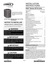
Figure 1
Installing the Outdoor Sensor
PROVIDED
SCREWS
OUTDOOR
SENSOR
5. Between the two mounting holes, drill a hole large
enough through which to pass the sensor wires,
thermostat wires, and wire nuts. See figure 1.
6. If using the plastic wall anchors push the anchors into
the holes drilled in step 4.
7. Install field-provided wires from the thermostat to the
outdoor sensor location. Use 22 gauge minimum solid
copper thermostat wire. The maximum length is 150
feet (46m).
8. Connect one end of the thermostat wires to the
terminals marked “T” on the thermostat subbase.
(Remove the thermostat from its subbase by grasping
the thermostat at the bottom and rotating it up and
outward.) The wires can be connected with either
polarity.
9. Connect the other end of the wires to the pigtails (with
either polarity) of the outdoor sensor using wire nuts.
Secure the wire nut to the wire using a few wraps of
electrical tape.
10. Seal the hole in the wall to eliminate any draft that
might affect the sensor.
IMPORTANT
The sensor will be inaccurate if the hole is not sealed
completely.
11. Seal the area where the pigtail wire exits the rear of the
outdoor sensor housing to prevent water from wicking
into the outdoor sensor housing. Apply a generous
bead of sealant to the rear housing in the area where
the wire exits the plastic housing. The sealant must be
located all around the wire exit area and be of sufficient
height to seal the hole drilled in step 5 once the housing
is secured to the mounting surface.
12. Carefully feed the excess wires into the hole.
13. Using the provided screws, attach the sensor to the
mounting surface.
14. Wipe off any excess sealant that may have oozed out
from the sides of the housing.
Specifications
The following are specifications for the X2658 Outdoor
Temperature Sensor:
•Two wires AWG#24 PVC 105°C.
•Wire length: 8 inches
•Measurement resolution: 1°F.
•Minimum measurable temperature: -60°F.
•Maximum measurable temperature: 182°F.
•Accuracy + 2°F.
•Electrical: 10K ohm + 1% at 77°F (25°C)
•Use 22AWG minimum thermostat wired up to 150 feet.
Figure 2
Dimensions
Testing Outdoor Sensor
Through the sensors, the thermostat or control can detect
outdoor temperature conditions. As the detected
temperature changes, the resistance across the sensor
changes. Table 1 shows how the resistance varies as the
temperature changes. Sensor resistance values can be
checked by ohming across pins shown in table 10.
NOTE — When checking the ohms across a sensor, be
aware that a sensor showing a resistance value that is not
within stated range may be performing as designed.
However, if a shorted or open circuit is detected, then the
sensor may be faulty and the sensor harness will need to
be replaced.

Page 3
X2658 SERIES
Table 1. Resistances versus Temperature
Temp oF (oC) Rmin Rnominal Rmax Temp oF (oC) Rmin Rnominal Rmax
-40 (-40) 184.4 191.8 199.6 42 (6) 20.85 21.22 21.60
-38 (-39) 174.7 181.7 188.9 44 (7) 20.01 20.36 20.71
-36 (-38) 165.6 172.1 178.9 46 (8) 19.21 19.53 19.86
-34 (-37) 157.0 163.1 169.4 48 (9) 18.44 18.74 19.05
-32 (-36) 149.0 154.6 160.5 50 (10) 17.71 17.99 18.28
-31 (-35) 141.3 146.6 152.1 51 (11) 17.01 17.27 17.54
-29 (-34) 134.1 139.1 144.2 53 (12) 16.34 16.59 16.84
-27 (-33) 127.3 132.0 136.8 55 (13) 15.70 15.93 16.17
-25 (-32) 120.9 125.3 129.8 57 (14) 15.09 15.31 15.53
-23 (-31) 114.9 118.9 123.1 59 (15) 14.51 14.71 14.91
-22 (-30) 109.2 113.0 116.9 60 (16) 13.95 14.14 14.33
-20 (-29) 103.7 107.3 111.0 62 (17) 13.42 13.59 13.77
-18 (-28) 98.64 102.0 105.4 64 (18) 12.91 13.07 13.24
-16 (-27) 93.81 96.94 100.2 66 (19) 12.42 12.57 12.73
-14 (-26) 89.24 92.17 95.18 68 (20) 11.95 12.10 12.24
-13 (-25) 84.92 87.66 90.48 69 (21) 11.50 11.64 11.77
-11 (-24) 80.84 83.40 86.04 71 (22) 11.08 11.20 11.33
-9 (-23) 76.97 79.37 81.84 73 (23) 10.67 10.78 10.90
-7 (-22) 73.30 75.56 77.87 75 (24) 10.28 10.38 10.49
-5 (-21) 69.83 71.94 74.11 77 (25) 9.900 10.00 10.10
-4 (-20) 66.55 68.52 70.55 78 (26) 9.533 9.633 9.733
-2 (-19) 63.43 65.29 67.19 80 (27) 9.181 9.281 9.381
-0.4 (-18) 60.48 62.22 64.00 82 (28) 8.845 8.944 9.043
1 (-17) 57.68 59.31 60.98 84 (29) 8.522 8.621 8.720
3 (-16) 55.03 56.55 58.12 86 (30) 8.213 8.311 8.410
5 (-15) 52.51 53.94 55.41 87 (31) 7.916 8.014 8.112
6 (-14) 50.12 51.46 52.84 89 (32) 7.632 7.729 7.827
8 (-13) 47.85 49.11 50.40 91 (33) 7.360 7.456 7.553
10 (-12) 45.70 46.88 48.09 93 (34) 7.099 7.194 7.290
12 (-11) 43.66 44.76 45.89 95 (35) 6.848 6.942 7.038
14 (-10) 41.71 42.75 43.81 96 (36) 6.607 6.701 6.795
16 (-9) 39.87 40.84 41.84 98 (37) 6.377 6.469 6.562
17 (-8) 38.12 39.03 39.96 100 (38) 6.155 6.247 6.339
19 (-7) 36.45 37.31 38.18 102 (39) 5.942 6.033 6.124
21 (-6) 34.86 35.67 36.48 104 (40) 5.738 5.827 5.918
23 (-5) 33.36 34.11 34.88 105 (41) 5.542 5.630 5.719
24 (-4) 31.92 32.63 33.35 107 (42) 5.353 5.440 5.528
26 (-3) 30.56 31.22 31.89 109 (43) 5.172 5.258 5.345
28 (-2) 29.26 29.88 30.51 111 (44) 4.998 5.083 5.168
30 (-1) 28.02 28.60 29.19 113 (45) 4.831 4.914 4.999
32 (0) 26.84 27.39 27.94 114 (46) 4.670 4.752 4.835
33 (1) 25.72 26.23 26.75 116 (47) 4.515 4.596 4.678
35 (2) 24.65 25.13 25.62 118 (48) 4.366 4.446 4.527
37 (3) 23.63 24.08 24.54 120 (49) 4.223 4.302 4.381
39 (4) 22.66 23.08 23.51 122 (50) 4.085 4.163 4.241
41 (5) 21.74 22.13 22.53
/