Page is loading ...

06/08 506061−01
*2P0608* *P506061-01*
E2008 Lennox Industries Inc.
Dallas, Texas, USA
COOLING
TUE OCT 23 1:15PM
Shipping and Packing List
1 − ComfortSenset Model L7742U touch screen, 7−day program-
mable thermostat
2 − Mounting screws (M3.5x25mm self−tapping screws)
2 − Wall Anchors
1 each − Installation Quick-Start Guide, Programming & Application
Guide, Homeowner’s Manual, Warranty card, Warranty Audit tag
PROGRAMMING AND
APPLICATION GUIDE
ComfortSenset 7000 Series
Model L7742U Touch Screen Programmable Thermostat
CONTROLS
506061−01
06/08
Supersedes 05/08
IMPORTANT
In commercial applications, the ComfortSenset Model L7742U
thermostat can only be used with approved split-system
matches, and those which meet the following installation crite-
ria:
Sinstallation uses 18 GAUGE thermostat wire or larger,
Sthermostat wire run length DOES NOT EXCEED 300’ (91m),
Sload from any thermostat connection is LESS THAN 1 AMP.
If used with Harmony II® Zone Control System, consult Applica-
tion Note H−04−5.
Litho U.S.A.

506061−01 06/08 Page 2
Table of Contents
ComfortSenset Model L7742U Thermostat 3. . . . . . . . . . . . .
Features 3. . . . . . . . . . . . . . . . . . . . . . . . . . . . . . . . . . . . . . . . . .
Display Fields & Touch Screen Points 4. . . . . . . . . . . . . . . . . .
Home ScreenCurrent Conditions & Temperature Settings 5
Controlling the Heat/Cool Modes of Operation 6. . . . . . . . . . .
Controlling the Fan Operation 7. . . . . . . . . . . . . . . . . . . . . . . . .
Schedule ScreenProgramming 8. . . . . . . . . . . . . . . . . . . . . .
Options screenReminders & User Settings 10. . . . . . . . . . . .
Options screenInstaller Settings 13. . . . . . . . . . . . . . . . . . . . .
Resetting Program to Factory Conditions 15. . . . . . . . . . . . . . .
EPA ENERGY STAR® Recommended Setpoints 16. . . . . . . . .
Humidification 18. . . . . . . . . . . . . . . . . . . . . . . . . . . . . . . . . . . . . .
Dehumidification 20. . . . . . . . . . . . . . . . . . . . . . . . . . . . . . . . . . . .
Humiditrol
® Enhanced Dehumidification Accessory (EDA) 21.
Stage Delay and Differential Settings 23. . . . . . . . . . . . . . . . . . .
Temporary Temperature ChangePause the Schedule 29. . .
Remote Outdoor Sensor 30. . . . . . . . . . . . . . . . . . . . . . . . . . . . .
Memory Protection 30. . . . . . . . . . . . . . . . . . . . . . . . . . . . . . . . . .
Date Code & Serial Number 31. . . . . . . . . . . . . . . . . . . . . . . . . .
Appendix A. Flow Diagrams & Wiring Diagrams 32. . . . . . . . . .
Appendix A. Diagnostic Information & Hidden Menu Tables 36
NOTE − This thermostat is equipped with automatic compressor
protection to prevent potential damage due to short cycling or extended
power outages. The short cycle protection provides a 5−minute delay
between heating or cooling cycles to prevent the compressor from be-
ing damaged.
WARNING
Always turn off power at the main power source by switching
the circuit breaker to the OFF position before installing or re-
moving this thermostat.
All wiring must conform to local and national building and elec-
trical codes and ordinances.
Do not switch system to cool if the outdoor temperature is be-
low 45°F (7°C). This can damage the cooling system.
CAUTION
This is a 24VAC low−voltage thermostat. Do not install on volt-
ages higher than 30VAC.
Do not short (jumper) across terminals on the gas valve or at the
system control to test installation. This will damage the thermo-
stat and void the warranty.
IMPORTANT
Read this manual before programming this thermostat.
Use this thermostat only as described in this manual.

ComfortSenset Model L7742U Touch Screen 7−Day Programmable Thermostat
Page 3
ComfortSenset Model L7742U Thermostat
Description
The ComfortSenset Model L7742U thermostat is an electronic 7−day
universal multi-stage programmable touch screen thermostat. It also
offers enhanced capabilities which include humidification measure-
ment and control, dew point adjustment control, dehumidification mea-
surement and control, Humiditrol® Enhanced Dehumidification Acces-
sory (EDA) capability, and equipment maintenance reminders. The
24VAC thermostat also features worry−free memory storage and a
menu−driven display. This document supports heat pumps or non−heat
pump units, with up to 4 stage heat / 2 stage cool heat pump (2 stages of
heat pump heating and 2 stages of auxiliary backup heat are provided.
Also, 2 stages of emergency heat are provided).
An optional outdoor temperature sensor (X2658) is required in applica-
tions with Humiditrol® EDA.
These instructions are intended as a general guide and do not super-
sede local codes in any way. Consult authorities having jurisdiction be-
fore installation.
Check equipment for shipping damage. If you find any damage, imme-
diately contact the last carrier.
Dimensions
Screen dimensions: 3−7/16" (87 mm) width x 2−9/16" (65 mm) height
Case dimensions: 5−7/8" (149 mm) width x 4−9/16" (116 mm) height x
1−1/4" (31mm) depth
Features
Outdoor Temperature Sensor (optional)
The outdoor sensor may be required, especially when using Humidi-
trol® EDA applications. In addition to measuring and displaying outdoor
temperature, the outdoor sensor provides dew point adjustment and
control for all models. If used with this thermostat, the sensor enables
optimal heating equipment operation via programmable balance points.
NOTE − The outdoor sensor uses standard thermostat wiring; it
may be wired using two wires of a multi−wire cable.
When the outdoor sensor is connected, the temperature is displayed in
the information display area (see figure 2).
NOTE − For proper operation of Humiditrol® EDA applications, the out-
door sensor (X2658) MUST be installed.
L" Input
L" input from the equipment is used to notify the user of an equipment
fault by displaying HVAC ERROR DETECTED" when one of the fol-
lowing conditions exist:
SL" terminal is activated with 24VAC and Y1 has been activated
for 5 minutes, OR,
SLSOM error signal is detected on L" input and Y1 has been acti-
vated for 5 minutes.
NOTE − If system is in battery mode, the L terminal is not functional. The
L input is used for diagnostic information purposes only, it is not in-
tended to provide equipment protection.
Compressor Short Cycle Protection
A 5−minute compressor short cycle protection timer begins when a
compressor output is de−energized. Also, if a power loss occurs, the
system will go into compressor protection mode and display WAIT in
the display if there is a cooling or compressor heating call.

506061−01 06/08 Page 4
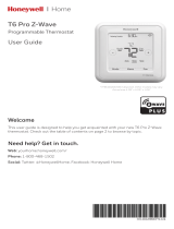
Display Fields & Touch Screen Points
A Selection Tab touch fields − Press to select: HOME (normal dis-
play), SCHEDULE (for programming), OPTIONS (to set alerts, ser-
vice reminders, and other user and installer settings).
A
B
C
DH
J
I
G
F
E
F
Figure 1. Touchscreen active fields
B MODE − press to cycle through HEAT, COOL, AUTO
(autochangeover), OFF, EM HEAT (emergency heat).
C FAN − press to cycle through ON, CIRC (circulate), AUTO.
D SCHED (schedule) − press to change between ON and OFF.
EDisplays the room temperature.
FDisplays the current operation SET AT point; if in AUTOchange-
over, both HEAT and COOL setpoints are identified.
GUp/down arrow touch fields used for adjusting temperature up or
down; if in AUTO (autochangeover) mode, 2 sets of up down ar-
rows.
HDisplays different information depending on the tab selected:
DHOME tab: displays outdoor temperature (if outdoor sen-
sor Lennox P/N X2658 is installed), indoor relative humid-
ity (RH), which mode is calling, hold settings information,
service reminders.
DSCHEDULE tab: displays the event being programmed;
DOPTIONS tab: displays a scrolling list of installer- and
user−adjustable parameters, including filter and service
reminder periods, etc.
ISchedule time adjustment, User/Installer Settings arrows:
DHOME screen: not visible except when executing a HOLD
SETTING)
DSCHEDULE and OPTION screens: used to adjust sched-
ule and option settings.
JDynamic touch fields − not visible in HOME screen unless execut-
ing a HOLD SETTING. For SCHEDULE and OPTIONS settings,
these boxes appear and change depending on the selection. See
the schedule and options sections for details.

ComfortSenset Model L7742U Touch Screen 7−Day Programmable Thermostat
Page 5
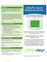
Home ScreenCurrent Conditions & Temperature Settings
INFORMATION
DISPLAY AREA
COOLING
TUE OCT 23 1:15PM
Figure 2. Home Screen
The HOME screen (figure 2) displays indoor temperature and outdoor
temperature if the X2658 sensor is installed outdoors and turned on in
user settings (outdoor sensor is required when humidity controlling fea-
tures are implemented). Other system operational information, such as
indoor relative humidity (if turned on in user settings), dehumidifying,
cooling or heating, will alternately be displayed in the information dis-
play.
The home screen displays temperature and the temperature settings in
large fonts. The INFORMATION DISPLAY shows the present day,
time, and operational information in a smaller font.
The menu tabs along the top of the screen are used to access the
SCHEDULE screen (for program setup) and the OPTIONS screen (to
access user/installer settings including, change to 24 hour clock,
change Fahrenheit to Celsius, set filter and service reminders, and
many other settings.
Equipment operation information appears in the boxes along the left
side of the home screen to indicate fan operation setting, cooling or
heating equipment operation setting, and whether or not scheduled pro-
gramming is ON or OFF. From these boxes, users can change the unit’s
mode to HEAT, COOL, AUTO (autochangeover − default), EM HEAT
(emergency heat for heat pump applications including dual fuel and HP
with Electric Heat), or OFF.
Also, the user can change the fan between ON (fan runs continuously
whether or not cool or heat equipment is running), AUTO (fan run time
controlled the schedule), or CIRC (circulate − user sets percentage of
fan run time).
The user can also decide whether or not to operate the unit per the pro-
grammable schedule, or in a non−programmable mode using the
SCHED box.

506061−01 06/08 Page 6
Controlling the Heat/Cool Modes of Operation
Press the screen anywhere − the first press turns on the backlight.
While in the HOME screen, press MODE field; repeated
presses scroll through all the modes. AUTO
(autochangeover) mode allows the thermostat to switch
between Heating and Cooling, whichever mode is dictated by
the indoor temperature. EM HEAT (emergency heat)
bypasses the first stage of heating (any stage[s] of heat pump
heating) and goes directly to the heat stage used for
maximum heating to more quickly warm a very cold house.
When the indoor temperature decreases or increases, the HEATING or
COOLING cycle will turn on based on the displayed mode. When the
HVAC system is on, the information display (shown in figure 3) will dis-
play one or several operational messages (listed in the table below). If
the outdoor sensor is connected, and is turned on in both installer and
user settings, outdoor temperature will be included in the displays. The
table below summarizes the information messages.
When the faults, errors, and service information displays appear, action
boxes will appear under the second line entries, REMIND, CLEAR,
SERVICE, or RESET. Press the box to perform the action.
Figure 3. Home Screen
Information Displays:
Faults, Errors, and Service Information Operating Information
TEMP SENSOR ERROR, MEMORY ERROR
CALL FOR SERVICE
Top line: fault/error
Bot. line: action
SET DATE/TIME
Default DATE/TIME (MON JAN 1 12:00 PM) [First time start up message]
NO OUTDOOR SENSOR
REMIND CLEAR SERVICE
Top line: fault/error
Bot. line: action
HEATING, COOLING, HUMIDIFYING, DEHUMIDIFYING,
SYSTEM OFF, OUTDOOR TEMP xxF, INDOOR RH xx%,
MON SEP 24 3:OO PM
Top line: operation messages
Bottom line: date and time
REPLACE: MEDIA FILTER; UV LAMP; HUM PAD; METAL INSERT
REMIND RESET
Top line: serv. req’d
Bot. line: action
SCHEDULE ON, SCHEDULE OFF, WAIT,
FAN ON, FAN CIRC
MON SEP 24 3:OO PM
Top line: add’l operation msgs
Bottom line: date and time
ROUTINE SYS CHECK−UP
REMIND RESET
Top line: serv. req’d
Bot. line: action
HOLD SETTING UNTIL PRESS SCHED TO
MON SEP 24 3:OO PM RESUME PROGRAM
[Alternating messages during
a held schedule]
NO OUTDOOR SENSOR, HUM SENSOR ERROR, HVAC ERROR DETECTED
REMIND SERVICE
Top line: fault/error
Bot. line: action
LOW BATTERY
REMIND
Top line:fault/error
Bot. line: action

ComfortSenset Model L7742U Touch Screen 7−Day Programmable Thermostat
Page 7
Controlling the Fan Operation
Press the screen anywhere − the first press turns on the backlight.
From the HOME screen press FAN field; repeated presses
scroll through all the modes, AUTO, ON, and CIRC
(circulate).
Fan Modes
Fan Modes (ON, AUTO and CIRC) can be changed either from HOME
screen or from the SCHEDULE screen when programming the thermo-
stat. The three settings work like this:
SIf FAN mode displays AUTO on the HOME screen, this means
that FAN is following the schedule.
SIf FAN mode displays ON on the HOME screen, this means that
the fan is NOT following the schedule and that the fan will run con-
tinuously until it is changed from the HOME screen.
SIf FAN mode displays CIRC on the HOME screen, this means that
the fan is NOT following the schedule and that the fan will cycle
during periods of equipment inactivity. The cycle time is depen-
dant on user settings FAN CIRCULATE (Page 11).
If FAN mode displays AUTO (HOME) and ON or CIRC was selected
during scheduling for the current period, the thermostat will indicate the
current fan mode in the information display (FAN ON or FAN CIRC).
In the CIRC mode, the user can cycle the fan for a programmed
percentage of active time per hour, during periods of equipment
inactivity (i.e., heating or cooling equipment not running). The fan is ON
for 5 minutes at a time. The user may change the percentage of ON time
that the fan is on (see FAN CIRCULATE [Page 11]):
Fan Program
The user can program the fan to be ON, AUTO, or CIRC during a
program event period. While scheduling the event, if the fan is set to
ON, it will remain on during the entire event. If it is set to CIRC, it will
circulate during equipment inactivity per user programmable cycles
(see FAN CIRCULATE, Page 11). If set to AUTO, the fan will come on
with the equipment to serve the heating/cooling demand and go off
accordingly. Using the fan continuously or circulating the fan during the
occupied times may better improve the indoor air quality.
NOTE − When the HOME screen FAN mode is changed to ON or CIRC,
whatever was scheduled is ignored − the fan will either be ON or it will
CIRCULATE per the user−programmed intervals (USER SETTINGS −
FAN CIRCULATE (Page 11). When FAN − AUTO is selected in the
HOME screen, the schedule IS followed.
Controlling the Schedule
Press the screen anywhere − the first press turns on the backlight.
From the HOME screen press SCHED; repeated presses
toggle the schedule ON and OFF. If ON, the system follows
the program developed by the user (Page 8). If OFF, the
system operates as a non−programmable thermostatthe
user must make changes when desired. The
autochangeover feature will continue to operate based on the
manual user inputs.

506061−01 06/08 Page 8
Schedule ScreenProgramming
Press the screen anywhere − the first press turns on the backlight.
Press the SCHEDULE tab along the top of the screen. The display
changes to programming mode (figure 4) and shows the current set-
tings. The thermostat may be programmed for two or four (default)
events per day. The names for the events are: WAKE, LEAVE, RE-
TURN, and SLEEP. The selected time for an event to occur is based on
when you want the event to begin. Four events are common for work-
ing households.
WAKE PERIOD BEGINS
5:OOAM
Figure 4. Schedule Screen
Programming may be performed in groups of days (5/2 or all 7) or indi-
vidual days, as follows:
AMON TO SUN − allows every day to be set the same.
BMON TO FRI (weekday programming) and
SAT TO SUN (weekend programming).
CMONDAY through SUNDAY allows individual days of the
week to be programmed separately.
NOTE − After using one of the groups of days described above, the
program does allow you to subsequently change individual days to suit
your needs.
To select the groupings or individual days, scroll through the selections
pressing NEXT.
Programming Complexity
The programming process for groups of days or individual days is the
same, except in the amount of times required to go through the process.
Full WeekThe least complex program is the full week MON TO
SUN" program, wherein the events for every day of the week are the
same. This requires one time through the event programming process.
Work WeekNext in complexity to the full week program is the work
week program wherein the events are set for a typical work week (MON
TO FRI) and different events are set for the weekend (SAT TO SUN).
This requires two times through the events.
Day by DayMost complex because this requires going through the
programming process 7 times.

ComfortSenset Model L7742U Touch Screen 7−Day Programmable Thermostat
Page 9
Days & Events Programming process
Action Display shows...
1 Press SCHEDULE tab SCHEDULE screen
2 Press EDIT UP/DOWN arrows on right−hand
side of screen; EDIT changes to
CANCEL
3 Press NEXT to highlight the de-
sired grouping of days
Days change to match selected
group, e.g. MON TUE WED THU FRI
4 Press an event: WAKE (default),
LEAVE, RETURN, & SLEEP to
select for programming
Filled triangle above event
indicates which event is selected
for change
5 Press UP/DOWN arrows to
select desired temperature
After change is made, SAVE
appears in the bottom right−hand
of the screen
6 Press FAN repeatedly to select
desired fan mode
Fan indicator displays selection
(ON, AUTO, or CIRC)
7 Press UP/DOWN arrows to
adjust start time for
selected event
Information area displays start
time
8 Repeat steps 4 − 7 for all remaining events.
(If you selected other than MON TUE WED THU FRI SAT SUN), continue;
otherwise, skip to step 11.
9 Press NEXT for the next group
or the next day
Days change to match selected
group, e.g. SAT SUN
10 Repeat steps 3 through 8 for the remaining days, if necessary.
11 Press SAVE when all events and
days are programmed as desired
The changes are made and the
schedule screen reappears.
24
6
1
7
5
WAKE PERIOD BEGINS
5:OOAM
911
3
Figure 5. Programming days and events

506061−01 06/08 Page 10
Options screenReminders & User Settings
CLEAN button
When you select the OPTIONS tab, two buttons appear near the bot-
tom of the screen labeled CLEAN and ENTER. Press the CLEAN but-
ton to deactivate the touch" zones for 30 seconds. Clean the screen
with a soft cloth and a mild glass cleaning solution.
The Options screen provides user and installer access to the various
features for setup and access to the reminders.
REMINDERS
USER SETTINGS
Reminders [OPTIONS TAB > REMINDERS > [ENTER] ]
Set timers from 1 to 24 months in either calendar time or system run
time. Reminders appear when it is time to service the following (for
more details on REMINDERS, see Page 31):
REPLACE MEDIA FILTER
DUE FRI FEB 15 O8
REPLACE METAL INSERT
DUE SUN SEP 14 O8
REPLACE HUM PAD
DUE FRI FEB 15 O8
REPLACE UV LAMP
DUE THU SEP 14 O8
ROUTINE SYS CHECK−UP
DUE IN 216O HOURS
CUSTOM REMINDERS
DUE SUN APR 13 O8
User Settings [OPTIONS TAB > USER SETTINGS > [ENTER] ]
Press the OPTIONS tab; use the arrows to select USER SETTINGS.
Press ENTER.
USER SETTINGS
INSTALLER SETTINGS
The following items are available for modifying. Follow the instructions
for each parameter.
DATE/TIMESet month, day, year, hour, and minute using DATE/
TIME option. Select DATE/TIME; press ENTER. Small, filled up-arrow
is selected column; use up/down arrows to adjust; press box below
each small up-arrow to select each column. Adjust; press SAVE.
FEB 11 2OO8 12PM 49
MON DAY YR HR MIN
CANCEL| | | | | |SAVE|

ComfortSenset Model L7742U Touch Screen 7−Day Programmable Thermostat
Page 11
F/Cdefault is Fahrenheit; to change to Celsius, scroll to F/C; press
ENTER. Use arrows to change to C; press SAVE.
F OR C
DEFAULT(F) F
12 OR 24 HOUR clockdefault is 12H; to change, scroll to 12 OR 24
HOUR; press ENTER. Use arrows to change to 24H; press SAVE.
12 OR 24 HOUR
DEFAULT(12HR) 12H
EVENTS DAILY 2 OR 4default is 4; to change, scroll to EVENTS
DAILY 2 OR 4; press ENTER. Use arrows to change to 2; press SAVE.
EVENTS DAILY 2 OR 4
DEFAULT(4) 2
DISPLAY INFOcontrols some of what is displayed in the field below
the temperature and above the time on the HOME screen; it may dis-
play OUTDOOR TEMP, INDOOR RH (relative humidity), or neither if
TEMP and RH are turned OFF. Scroll to DISPLAY INFO; press EN-
TER. Use arrows to select TEMP or RH; press ENTER.
DISPLAY INFO
OUTDOOR TEMP
INDOOR RH
NOTE − When accessing the OUTDOOR TEMP option OUT-
DOOR SENSOR REQUIRED" will display if not turned ON in the
installer settings. The home screen will display NO OUTDOOR
SENSOR" if the physical sensor is not installed.
For INDOOR RH, use arrows to select ON or OFF; then press SAVE.
INDOOR RH
DEFAULT(OFF) ON
For OUTDOOR TEMP, select ON or OFF; then press SAVE.
OUTDOOR TEMP
DEFAULT(OFF) ON
HUMIDITROL ADJUSTIf Humiditrol is enabled in the installer set-
tings, then this adjustment affects overcooling operation. Overcooling
ranges from 2ºF below the cooling setpoint (MIN setting) down to 2ºF
above the heating setpoint (MAX setting). Halfway between the two
settings is the MID setting. The default setting is MAX; to change to MID
or MIN, scroll to HUMIDITROL ADJUST; press ENTER. Use arrows to
scroll to MID or MIN; then press SAVE.
HUMIDITROL ADJUST
DEFAULT (MAX) MIN
NOTE − Humiditrol does not function if the outdoor temperature is 95ºF
or greater nor when t he indoor temperature is 65ºF or less.
FAN CIRCULATEAs an option to running the fan all the time, CIRCu-
late allows the user to decide how much the fan will run during periods of
equipment inactivity. The fan ON time is always set to 5 minutes. This
option will cause the fan to come on more or less frequently. The default
is 35%; to change, scroll to FAN CIRCULATE; press ENTER. Use ar-
rows to change to 15, 25, or 45%; press SAVE.
FAN CIRCULATE
DEFAULT(35%) 25%
15% (9 minutes fan run time per hour)
25% (15 minutes fan run time per hour)
35% (21 minutes fan run time per hour)
45% (27 minutes fan run time per hour).

506061−01 06/08 Page 12
Options screenReminders & User Settings(continued)
COOLING LIMITdefault is 45º; to change to any degree between
45ºF and 99ºF, scroll to COOLING LIMIT; press ENTER. Use arrows to
change to desired temperature; press SAVE.
COOLING LIMIT
DEFAULT(45°F) 55°F
HEATING LIMITdefault is 90º; to change to any degree between
45ºF and 90ºF, scroll to HEATING LIMIT; press ENTER. Use arrows to
change to desired temperature; press SAVE.
HEATING LIMIT
DEFAULT(9O°F) 85°F
SECURITY LOCKdefault − no locks at all − this provides two methods
of locking the thermostat − NO prevents others from making any
changes at all or YES prevents others from making changes other than
temperature setpoints. Scroll to SECURITY LOCK and press ENTER;
ALLOW TEMP ADJUST screen appears; press box below YES or NO.
The ENTER LOCK CODE screen appears.
ALLOW TEMP ADJUST
YES NO
ENTER LOCK CODE
OO O
| | | | |
NOTE − If the user settings security code is forgotten or misplaced for
some reason, the universal code 864" may be used to unlock.
To enter lock code, press box below each small up-arrow to select each
column. Use up/down arrows to enter a number, then press the box be-
low the next number and repeat to enter a 3-digit lock code; write down
the number for future reference; press SAVE.
HUMIDITY SETTINGSee separate sections − Humidify (Page 18)
and Dehumidify (Page 20).
BACKLIGHT SETTINGdefault is POWER SAVE; scroll to BACK-
LIGHT SETTING; press ENTER. Use arrows to change to CONTINU-
OUS; press SAVE.
BACKLIGHT SETTING
DEF(SAVE) POWER SAVE
BACKLIGHT INTENSITYdefault is 100%; scroll to BACKLIGHT IN-
TENSITY; press ENTER. Use arrows to change to 20 to 100% in 20%
increments; press SAVE.
BACKLIGHT INTENSITY
DEFAULT(1OO%) 8O%

ComfortSenset Model L7742U Touch Screen 7−Day Programmable Thermostat
Page 13
Options screenInstaller Settings
Installer Settings
[OPTIONS TAB > INSTALLER SETTINGS > [ENTER] [ENTER] ]
Press OPTIONS tab, then use the arrows to select INSTALLER SET-
TINGS. Press ENTER twice.
INSTALLER SETTINGS
−−−−−−−−−−−−−−−−−−−−
NOTE − After the first Enter", a note states MUST BE SET BY QUAL-
IFIED PERSON". Press Enter again to access installer settings.
The following items are available for modifying. Follow the instructions
for each parameter.
SYSTEM SETUPSets the thermostat for operation with a heat pump
or non-heat pump and defines the number of compressor stages and
the number of backup heat stages. The default settings for the system
are Non−heat Pump, Gas/Oil, 2 compressor stages, 2 indoor heat
stages.
Use arrows to select from the list; then press ENTER.
SYSTEM SETUP
NON HEAT PUMP
HEAT PUMP
COMPRESSOR STAGES
INDOOR HEAT STAGES
For NON HEAT PUMP, use arrows to select backup heat: NO HEAT,
GAS/OIL, or ELECTRIC; then press SAVE.
NON HEAT PUMP
NO HEAT
GAS/OIL
ELECTRIC
For HEAT PUMP, use arrows to select backup heat: NO BACKUP
HEAT, DUAL FUEL (GAS/OIL), or ELECTRIC; then press SAVE.
HEAT PUMP
NO BACKUP HEAT
DUAL FUEL (GAS/OIL)
ELECTRIC
For COMPRESSOR STAGES, use arrows to select either 1 or 2 com-
pressor stages; then press SAVE.
COMPRESSOR STAGES
2
For INDOOR HEAT STAGES, use arrows to select 1 or 2 indoor heat
stages; then press SAVE.
INDOOR HEAT STAGES
2
OUTDOOR SENSORdefault NO. Balance points, Humiditrol, Dew
Point Control require an outdoor sensor. This control sets the thermo-
stat to test for and report outdoor temperature. Scroll to OUTDOOR
SENSOR and press ENTER; use arrows to select YES; press SAVE.
OUTDOOR SENSOR
DEFAULT(NO) YES
NOTE − If outdoor sensor is not present and if user tries to select the
options DISPLAY INFO −> OUTDOOR TEMP, LOW BALANCE POINT,
HIGH BALANCE POINT, DEW POINT CONTROL, HUMIDITROL a
message is displayed OUTDOOR SENSOR REQUIRED" instead of
scroll options for these menus. Information about installing the sensor
is described on Page 30.
RESIDUAL COOLdefault is zero seconds. This is the time, in sec-
onds, that the fan runs after a call for cooling is satisfied in order to deliv-
er any residual cooling ability from the coil and ductwork into the condi-
tioned space. Scroll to RESIDUAL COOL; press ENTER. Use arrows
to select seconds: 0, 30, 60, 90, and 120; press SAVE.
RESIDUAL COOL
DEFAULT(OS) 6OS

506061−01 06/08 Page 14
Options screenInstaller Settings (continued)
LOW BALANCE POINTdefault 25°F (heat pump only, and if outdoor
sensor installed). If outdoor temperature is below programmed Low
Balance Point, compressor heating is not allowed. The options are OFF
or any point from −40°F to the High Balance Point setting in 1.0°F steps.
LOW BALANCE POINT
DEFAULT(25°F) 25°F
HIGH BALANCE POINTdefault is 50°F (heat pump only, and if out-
door sensor installed). If outdoor temperature is above the High Bal-
ance point, then auxiliary heat is not allowed. The options are OFF or
any point from the Low Balance Point up to 75°F in 1.0°F steps.
HIGH BALANCE POINT
DEFAULT(5O°F) 45°F
DEADBANDdefault is 4°F. The deadband setting is the minimum dif-
ference between the cooling and heating setpoints. This setting is used
in autochangeover mode to ensure smooth equipment operation and
allows for flexibility in Humiditrol® EDA operation. The deadband is ad-
justable from 3 to 8°F.
DEADBAND
DEFAULT(4°F) 5°F
SMOOTH SET BACK(SSR) default is ON. When enabled, SSR be-
gins recovery up to 2 hours before the programmed time, such that the
programmed temperature is reached at the corresponding pro-
grammed event time. Assume 12°F per hour for first stage gas/electric
heating and 6°F per hour for first stage compressor based heating or
cooling. With SSR disabled, the control will start a recovery at the pro-
grammed time. Scroll to SMOOTH SET BACK; press ENTER. Use ar-
rows to select between ON or OFF. Press SAVE.
SMOOTH SET BACK
DEFAULT(ON) OFF
SSR STG2 LOCK OUTdefault is 20 minutes. Second stage opera-
tion is not allowed until the last 20 minutes before the programmed start
time. Use this setting to change the time. Scroll to SSR STG2 LOCK
OUT; press ENTER. Use arrows to select minutes that 2nd stage will be
locked out (20 to 120 min. in 10 min. increments). Press SAVE.
SSR STG2 LOCK OUT
DEFAULT(2OMIN) 4OMIN
CONTACT INFORMATIONdefault is CONTACT INSTALLING
DEALER. This may be programmed with the dealer or technical service
contact. Scroll to CONTACT INFORMATION; press ENTER. A cursor
appears to the left of the first line. Use arrows to select letters, numbers,
and special characters. When the first character is identified, press
NEXT to advance to the next character; repeat to input the desired con-
tact information. Press SAVE when finished.
CONTACT
INSTALLING DEALER
TEMPERATURE OFFSETdefault is 0°F. This setting can be used to
offset the displayed space temperature by up to +/− 5°F. This offset also
applies to the control temperature. Scroll to TEMPERATURE OFFSET;
press ENTER. Use arrows to select a new offset. Press SAVE.
TEMPERATURE OFFSET
DEFAULT(O°F) 3°F
HUMIDITY OFFSETdefault is 0%. This can be used to offset the dis-
played and controlled space relative humidity (RH) by up to +/− 10%
RH. Scroll to HUMIDITY OFFSET; press ENTER. Use arrows to select
a new offset. Press SAVE.
HUMIDITY OFFSET
DEFAULT(O%) 2%
See separate section (Page 23) for details.

ComfortSenset Model L7742U Touch Screen 7−Day Programmable Thermostat
Page 15
COMPRESSOR PROTECTdefault is ON; it may be turned OFF,
however, after one compressor cycle, it will revert back to ON. If the
system is running in compressor protection, the home screen displays
WAIT" only if there is cooling or heating call for the compressor
(Y1/Y2). If compressor protection is running and there is a demand for
electric heating, the system waits for the compressor protection timer to
expire. Scroll to COMPRESSOR PROTECT; press ENTER. Use up/
down arrows to select OFF. Press SAVE.
COMPRESSOR PROTECT
DEFAULT(ON) OFF
DAYLIGHT SAVING TIME (DST)default setting is ON (enabled).
Note: Beginning in 2007, DST will begin on the second Sunday in March
and end the first Sunday in November. In the U.S., clocks spring for-
ward from 1:59 a.m. to 3:00 a.m.; in fall, clocks fall back from 1:59 a.m.
to 1:00 a.m. If the community or state opts out of DST, turn this OFF.
Scroll to DAYLIGHT SAVING TIME; press ENTER. Use up/down ar-
rows to select OFF. Press SAVE.
DAYLIGHT SAVING TIME
DEFAULT(ON) OFF
HUMIDITY SETTINGSee separate sections − Humidification
(Page 18) and Dehumidification (Page 20).
STAGE DELAY AND DIFFERENTIAL SETTINGSThe differential or
delay settings in the Installer Settings menu are:
STG DELAY TIMERS
STG 1 DIFF
STG 2 DIFF
STG 2 DELAY
STG 3 DIFF
STG 3 DELAY
STG 4 DIFF
STG 4 DELAY
H/C STGS LOCKED IN
STG 2 HP LOCK TEMP
See Page 23 for more stage delay and differential details.
CUSTOM REMINDERSTwo additional reminders may be created
using a text message. This will appear in the list of reminders and the
user can then select the time for the reminder to be displayed. Scroll to
CUSTOM REMINDER 1 or 2. Press ENTER. To create a reminder,
press EDIT.
CUSTOM REMINDER 1
A cursor will appear on the second line. Use the arrows to scroll through
letters, numbers and special characters. When the desired character
appears, press NEXT to advance to the right by one character. Contin-
ue until the message is complete (up to 19 characters). When finished,
press SAVE.
CUSTOM REMINDER 1
CLEAN OUTDOOR UNIT
RESET SETTINGSTo reset the ComfortSenset Model L7742U
thermostat to factory defaults, scroll to RESET SETTINGS.
IMPORTANT
This erases all programming and returns the thermostat to the
factory conditions, including the installer settings. Use this
only as a last resort.
With RESET SETTINGS selected, press ENTER. Press the box below
YES to reset; RESETTING SETTINGS TO DEFAULTS appears briefly
and then returns to the INSTALLER SETTINGS list.
RESET SETTINGS
YES NO
| |

506061−01 06/08 Page 16
Options screenInstaller Settings (continued)
Hardware reseta hardware reset may be performed if necessary.
This procedure requires separating the thermostat from the base and
shorting across points A and B as shown in figure 6.
All the settings will be restored from EEPROM.
B
A
Figure 6. Hardware Reset Points
ENERGY STAR DEFAULTEPA ENERGY STAR® recommended
setpoints for heating and cooling can help the household save energy.
The following time and temperatures are preprogrammed into the con-
trol to conform to Energy Star requirements.
NOTE − Humidification
and dehumidification
Table 1. ENERGY STAR® Setpoints
and dehumidification
are not
p
art of the EN- Time Heating Cooling
are
not
part
of
the
EN
-
ERGY STAR® pro- Wake 70°F (21°C) 78°F (25°C)
ERGY
STAR
pro
gram. A higher utility
bill may occur when not
Leave 62°F (17°C) 85°F (29°C)
bill may occur when not
us
in
g
t
h
e
setpo
in
ts
in Return 70°F (21C) 78°F (25°C)
using
the
setpoints
in
this table. Sleep 62°F (17°C) 82°F (28°C)
Scroll to ENERGY STAR DEFAULT; press ENTER. Press the box be-
low YES to reset; ENERGY STAR SETTING appears briefly and then
returns to the installer setting listing.
ENERGY STAR DEFAULT
YES NO
| |

ComfortSenset Model L7742U Touch Screen 7−Day Programmable Thermostat
Page 17
SYSTEM TEST MODESAfter the thermostat has been installed and
set−up, the installer may run a system test function (accessed through
the installer settings menu), to test all cooling, heating, Emergency
Heating stages and FAN outputs. Scroll to SYSTEM TEST MODES
and press ENTER; select TEST OUTPUTS and press ENTER.
SYSTEM TEST MODES
TEST OUTPUTS
SCROLL arrows move through a list of all signals, Y1 ON, Y1 OFF, Y2
ON, Y2 OFF, etc. With a signal displayed, press ENTER to start the
test, (e.g. Y1 ON selected, press ENTER brings on Y1; Y1 OFF se-
lected, press ENTER shuts off Y1. CANCEL, pressed at anytime dur-
ing tests will return the previous screen and also disable any test and
puts the thermostat back into normal mode.
CAUTION
In dual fuel system applications, do not turn on heat pump and
furnace at the same time in system test mode.
All HVAC components can be tested to confirm the signals between
thermostat and unit are being sent and received.
NOTES − After 5 minutes without a test being initiated, the test modes is
disabled and system goes back to the normal mode (i.e. HOME
screen).
When in SYSTEM TEST MODE, the compressor minimum off timer is
bypassed.
TEST OUTPUTS
OFF
Y1 ON
Y1 OFF
Y2 ON
Y2 OFF
W1 ON
W1 OFF
W2 ON
W2 OFF
FAN (G) ON
FAN (G) OFF
H ON
H OFF
D ON
D OFF
O ON (B OFF)
B ON (O OFF)

506061−01 06/08 Page 18
Humidification
INSTALLER SETTINGS
Humidification (adding moisture to air) is provided only when the ther-
mostat is in heat mode. The humidification signal (H terminal) to the hu-
midifier (off when the thermostat is in the COOL mode) controls humidi-
fication. When the thermostat is powered, the H terminal is normally
inactive (open circuit) in any mode (HEAT, COOL, OFF). When a hu-
midification demand is present, H terminal and G terminal are ener-
gized (24V).
HUMIDITY SETTINGdefault OFF. Installer settings must be
turned on before the user will have control over the humidity. The
mode selected determines how the user can adjust the relative humid-
ity (RH). The installer settings include BASIC, PRECISION, DEW-
POINT, and OFF.
BASIC & PRECISIONthese thermostat modes allow the user to con-
trol the relative humidity (RH) between 15 and 45%. The following con-
ditions must be met for either mode to operate:
Shumidification mode has been enabled, and
Sthe unit is in HEAT mode, and
Shumidification demand exists (24V present at H), and
Additionally, the BASIC mode requires:
Sheat demand exists (W energized [for gas heat, W may be ener-
gized with G de−energized]).
Scroll to HUMIDITY SETTINGS; press ENTER. Press the box below
HUMIDIFY.
HUMIDITY SETTINGS
HUMIDIFY DEHUMIDIFY
| |
Use up/down arrows to select BASIC or PRECISION; press ENTER.
HUM MODE SETTING
DEF(OFF) PRECISION
Default setting is 45% RH. Use up/down arrows to define what NEW
SETPOINT IS (between 15 to 45%); then press SAVE.
HUM SETPOINT
DEFAULT (45%) 4O%
DEWPOINTDewpoint adjustment mode will change the humidifica-
tion setpoint based on the outdoor temperature and a user−defined dew
point adjustment setting.
NOTE − In dew point adjustment mode, the humidification setpoint has
no effect whatsoever on unit operation. Only the user−defined dew point
adjustment setting affects operation per the following formula:
RHsetpoint =Outdoor Temp (ºF)
2+ 25 + RHuser dew point adjust-
ment
Where: RHuser dew point adjustment cannot exceed +/−15% and
RHsetpoint minimum is 15% and cannot exceed 45%.
Scroll to HUMIDITY SETTINGS; press ENTER.
HUMIDITY SETTINGS
HUMIDIFY DEHUMIDIFY
| |
Press the box below HUMIDIFY. Use up/down arrows to select DEW-
POINT; press ENTER.
HUM MODE SETTING
DEF(OFF) DEWPOINT
Use up/down arrows to select NEW DEWPOINT ADJ setpoint (be-
tween +15 to −15%); then press SAVE.
DEW POINT ADJ
DEFAULT (O%) −5%
NOTE − Dewpoint adj available only when outdoor sensor is attached.

ComfortSenset Model L7742U Touch Screen 7−Day Programmable Thermostat
Page 19
USER SETTINGS
BASIC & PRECISIONif set up by the installer settings for BASIC or
PRECISION, this adjustment controls the relative humidity (RH) be-
tween 15 and 45%.
Scroll to HUMIDITY SETTINGS; press ENTER. Press the box below
HUMIDIFY.
HUMIDITY SETTINGS
HUMIDIFY DEHUMIDIFY
| |
Use up/down arrows to change the humidity setpoint (between 15 and
45%); press SAVE.
HUM SETPOINT 45%
DEFAULT (45%) 4O%
DEWPOINTif set up by the installer settings for DEWPOINT, this ad-
justment (only when in heating mode) will change the humidification
setpoint based on the outdoor temperature and a user−defined dew
point adjustment setting. When humidifying, if condensation forms on
the windows, the dewpoint should be adjusted in the range of −15 to
−5%; if the home feels dry, set dewpoint upward in the range of +5 to
+15%.
Scroll to HUMIDITY SETTINGS; press ENTER. Press the box below
HUMIDIFY.
HUMIDITY SETTINGS
HUMIDIFY DEHUMIDIFY
| |
Use up/down arrows to change the dewpoint (between +15 and −15%);
press SAVE.
DEW POINT ADJ O%
DEFAULT (O%) −5%
NOTE − Dewpoint adj available only when outdoor sensor is attached.
OFFif OFF selected in installer settings for both humidify and dehu-
midify, this message appears when HUMIDITY SETTING is pressed:
HUMIDITY MODES OFF
If OFF is selected by the installer settings for HUMIDIFY but DE-
HUMIDIFY is on, the dehumidification menu appears (this setpoint ad-
just has NO effect on humidification):
DEHUM SETPOINT 50%
DEFAULT (5O%) 45%

506061−01 06/08 Page 20
Dehumidification
INSTALLER SETTINGS
Dehumidification (removing moisture from air) can occur only when the
thermostat is in cool mode. When a dehumidification demand is pres-
ent, a dehumidification signal (0VAC − open circuit) is present at the D
terminal. This is used to reduce the speed of the indoor blower during
dehumidification. At the same time, the Y1 and Y2 (if available) termi-
nals become activated with 24VAC. The H terminal is inactive (0VAC −
open circuit) during dehumidification.
NOTE − The D terminal is ALWAYS activated (24VAC) when the ther-
mostat is in HEAT or OFF mode; it is only inactive (0VAC − reverse log-
ic) during dehumidification.
Dehumidification adjustment will change the relative humidity (RH) set-
ting between 45 to 60% RH (default setting is 50% RH). The lower the
number, the more humidity will be removed from the air.
HUMIDITY SETTINGdefault OFF. Installer settings must be
turned on before the user will have control over the humidity. The
mode selected determines how the user can adjust the relative humid-
ity (RH). The installer settings include BASIC, PRECISION, HUMIDI-
TROL, and OFF.
Dehumidification Modes
In BASIC mode, dehumidification occurs if these conditions are met
and signals are present at specific terminals:
Sdehumidification has been enabled on installer settings, and
Sthe unit is in COOL mode, and
Sdehumidification demand exists (RH above setpoint), and
Scooling demand exists (Y1 energized).
In PRECISION mode, dehumidification occurs if all BASIC conditions
are true, except cooling demand may or may not be present. Maximum
over cool from cooling set point is 2ºF.
HUMIDITROL mode requires:
Soutdoor sensor must be installed and setup
Sdehumidification has been enabled on installer settings, and
Sthe unit is in COOL mode, (or if in AUTO, there has been at least
one thermostat cooling call made prior to the dehumidification de-
mand), and
Sa dehumidification demand exists (RH above setpoint), and
Soutdoor temperature is below 95°F, and
Sindoor temperature is above 65°F, and
Sthe room temperature meets Humiditrol adjustment parameters
as follows:
DMAX adj. − Indoor temp > 2°F above heating setpoint
DMID adj. − Indoor temp > HEAT SETPOINT+COOL SETPOINT
2
DMIN adj. − Indoor temp > 2°F below cooling setpoint
Scroll to HUMIDITY SETTINGS; press ENTER. Press the box below
DEHUMIDIFY.
HUMIDITY SETTINGS
HUMIDIFY DEHUMIDIFY
| |
Use up/down arrows to scroll to BASIC or PRECISION; press ENTER.
DEHUM MODE SETTING
DEF(OFF) PRECISION
Default setting is 50% RH. Use up/down arrows to change the %RH;
press SAVE.
DEHUM SETPOINT
DEFAULT (5O%) 45%
USER SETTINGS
BASIC, PRECISION, HUMIDITROLif set up by the installer settings
for BASIC, PRECISION or HUMIDITROL, this adjustment controls the
relative humidity (RH) between 45 and 60% (default 50%).
/