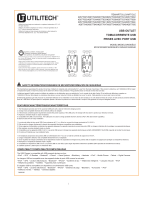
MODEL/MODELO/MODÈLE #2004A
ITEM/ARTÍCULO/ARTICLE
#2677720/#2677721/#2677722
WARNING: TO AVOID FIRE, SHOCK, OR DEATH; TURN OFF POWER AT CIRCUIT BREAKER OR FUSE AND TEST THAT THE POWER IS OFF BEFORE WIRING!
ADVERTENCIA: PARA EVITAR INCENDIOS, DESCARGAS O LA MUERTE, APAGUE EL SUMINISTRO ELÉCTRICO EN EL INTERRUPTOR DE CIRCUITO O EL FUSIBLE Y COMPRU-
EBE QUE ESTÉ APAGADO ANTES DE REALIZAR EL CABLEADO.
AVERTISSEMENT : AFIN D’ÉVITER LES RISQUES D’INCENDIE, DE CHOC ÉLECTRIQUE OU DE DÉCÈS, COUPEZ L’ALIMENTATION ÉLECTRIQUE DEPUIS LE DISJONCTEUR OU
LE FUSIBLE ET VÉRIFIEZ QUE L’ALIMENTATION EST BIEN COUPÉE AVANT D’EFFECTUER LE CÂBLAGE.
Connect wires per WIRING DIAGRAM as follows:
Conecte los conductores según se muestra en el DIAGRAMA DE CABLEADO:
Branchez les fils conformément au SCHÉMA DE CÂBLAGE comme suit :
WARNING: TO BE INSTALLED AND/OR USED IN ACCORDANCE WITH APPROPRIATE ELECTRICAL CODES AND REGULATIONS. IF YOU ARE NOT SURE ABOUT ANY PART OF THESE INSTRUC-
TIONS, CONSULT A QUALIFIED ELECTRICIAN.
WARNING: USE THIS DEVICE ONLY WITH COPPER OR COPPER CLAD WIRE. WITH ALUMINUM WIRE USE ONLY DEVICES MARKED CU/AL.
ADVERTENCIA: PARA INSTALARSE O USARSE DE ACUERDO CON LOS CÓDIGOS Y LAS NORMAS ELÉCTRICAS CORRESPONDIENTES. SI NO ESTÁ SEGURO ACERCA DE ALGUNA PARTE DE
ESTAS INSTRUCCIONES, CONSULTE A UN ELECTRICISTA CALIFICADO.
ADVERTENCIA: USE ESTE DISPOSITIVO SOLAMENTE CON UN CONDUCTOR DE COBRE O RECUBIERTO DE COBRE. CON CONDUCTOR DE ALUMINIO UTILICE SOLO DISPOSITIVOS MARCADOS
CU/AL.
AVERTISSEMENT : À INSTALLER OU À UTILISER CONFORMÉMENT AUX CODES DE L’ÉLECTRICITÉ ET AUX RÈGLEMENTS APPLICABLES. SI VOUS NE COMPRENEZ PAS L’UNE DES PARTIES DE
CES INSTRUCTIONS, CONSULTEZ UN ÉLECTRICIEN QUALIFIÉ.
AVERTISSEMENT : UTILISEZ UNIQUEMENT CET APPAREIL AVEC UN FIL EN CUIVRE OU REVÊTU DE CUIVRE. UTILISEZ UNIQUEMENT LES APPAREILS PORTANT LA MENTION CU/AL AVEC UN FIL
EN ALUMINIUM.
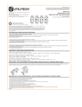
FOR SEPARATE FEED CONVERSION ONLY: This device is provided with break-off fins located between the terminal screws. To control the top outlet and the bottom outlet with
two different hot wires (two circuits), remove the break-off fin between the two HOT terminal screws (brass or black) before wiring. Use needle nose pliers and bend fin back and
forth until it breaks off.
SOLO PARA LA CONVERSIÓN DE ALIMENTACIÓN POR SEPARADO: este dispositivo está provisto de aletas desprendibles ubicadas entre los tornillos de los terminales. Para
controlar el tomacorriente superior y el tomacorriente inferior con dos conductores energizados diferentes (dos circuitos), retire la aleta desprendible entre los dos tornillos de los
terminales energizados (brass o negro) antes de realizar el cableado. Use pinzas de punta fina y doble la aleta hacia delante y hacia atrás hasta que se rompa.
POUR CONVERSION D’ALIMENTATION DISTINCTE SEULEMENT : Cet appareil est doté d’ailettes détachables situées entre les vis de borne. Pour contrôler la prise supérieure
et la prise inférieure avec deux fils chargés différents (deux circuits), retirez l’ailette détachable entre les deux vis de borne CHARGÉES (en laiton ou noires) avant le câblage.
Utilisez des pinces à bec effilé et pliez l’ailette d’avant en arrière jusqu’à ce qu’elle se détache.
NOTE: If the device surface is marked with WR, both indoor and outdoor use are acceptable. Otherwise it should be indoor use only.
NOTA: si la superficie del dispositivo está marcada con WR, se acepta tanto el uso en interiores como en exteriores. De lo contrario, debe usarse solo en interiores.
REMARQUE : Si la surface de l’appareil porte la mention WR, vous pouvez l’utiliser à l’intérieur ou à l’extérieur. Sinon, il ne doit être utilisé qu’à l’intérieur.
Before returning to your retailer, call our customer service department at 1-866-994-4148, 8 a.m. - 8 p.m., EST, Monday - Sunday. You could also contact
Antes de volver a la tienda, llame a nuestro Departamento de Servicio al Cliente al 1-866-994-4148, de lunes a domingo de 8 a.m. a 8 p.m. hora
estándar del Este. También puede ponerse en contacto con nosotros escribiendo a
[email protected] o visite www.lowespartsplus.com
Avant de retourner l’article au détaillant, appelez notre service à la clientèle au 1 866 994-4148, entre 8 h et 20 h (HNE), du lundi au dimanche. Vous
pouvez également nous écrire à l’adresse
[email protected] ou visiter le site Web www.lowespartsplus.com
Questions, problems, missing parts?
¿Preguntas, problemas, piezas faltantes?
Des questions, des problèmes, des pièces manquantes?
Printed in China
Impreso en China
Imprimé en Chine
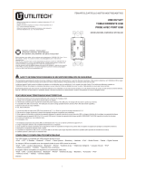
WARNING/ADVERTENCIA/AVERTISSEMENT :
2. Mount device in wall box with screws provided and mount wall plate.
3. Restore power at circuit breaker or fuse.
4. Installation is complete.
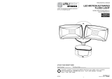
1(A). To Side Wire (Figure A):
2. Monte el dispositivo en la caja de pared con los tornillos provistos y monte la placa de pared.
3. Vuelva a conectar la alimentación en el interruptor de circuito o en el fusible.
4. La instalación está terminada.
1(A). Al conductor lateral (Figura A):
2. Fixez l’appareil dans la boîte murale avec les vis fournies, puis fixez la plaque murale.
3. Rétablissez l’alimentation électrique depuis le disjoncteur ou les fusibles.
4. L’installation est terminée.
1(A). Fil latéral (figure A) :
Figure A/Figura A/figure A
DECORATOR RECEPTACLE
TOMACORRIENTE DECORATIVO
PRISE DÉCORATIVE
SM20448
Remove approximately 5/8" (1.6 cm) insulation from wire. Push neutral wire (white) into the bottom of the round wire hole marked WHITE WIRE. Push hot wire (black) into the bottom
of the round wire hole marked HOT WIRE. This device must be properly grounded for electrical shock protection. Connect green or bare grounding wire to the green-colored terminal
screw.
Retire aproximadamente 15,87 mm (5/8 pulg.) de aislamiento del conductor. Presione el conductor neutro (blanco) en la parte inferior del orificio del conductor redondo marcado con
WHITE WIRE (conductor blanco). Presione el conductor energizado (negro) en la parte inferior del orificio del conductor redondo marcado con HOT WIRE (conductor energizado).
Este dispositivo debe estar correctamente conectado a tierra para protegerlo contra descargas eléctricas. Conecte el conductor de puesta a tierra verde o desnudo al tornillo del
terminal de color verde.
Retirez environ 1,6 cm (5/8 po) d’isolant du fil. Enfoncez le fil neutre (blanc) dans la partie inférieure du trou rond pour fil portant la mention WHITE WIRE (fil blanc). Enfoncez le fil
chargé (noir) dans la partie inférieure du trou rond pour fil portant la mention HOT WIRE (fil chargé). Cet appareil doit être correctement mis à la terre pour réduire les risques de choc
électrique. Raccordez le fil de mise à la terre vert ou dénudé à la vis de borne verte.
Utilitech and logo design are trademarks or registered trademarks of LF, LLC. All rights reserved.
Utilitech y el diseño de logotipos son marcas o marcas registradas de LF, LLC. Todos los derechos reservados
Utilitech et le logo sont des marques de commerce ou des marques de commerce déposées de LF, LLC. Tous droits réservés.

 1
1

 Utilitech 2008-WH10 Installation guide
 Utilitech R1820D60AAC-LA2 Installation guide
 Utilitech R1615D40-IV2 Installation guide
 Utilitech R164U40-LA2 Installation guide
 Utilitech 7116-02 User manual
 Utilitech 7111-04-L Installation guide
 Utilitech UT-27103-02 Installation guide
 Utilitech AHR 100-00 Dusk to Dawn Light User manual
 Utilitech 7113-01-L Installation guide
 Utilitech SE1019-TBZ-02LF0-U Operating instructions


