Utilitech Pro MXL2005-LED1X20K840 Installation guide
- Category
- Serial switch boxes
- Type
- Installation guide

1
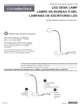
STRIP LIGHT
ITEM #0595682, 0595683, 0595684, 0595685
MODEL #MXL2005-LED1X10K840
MXL2005-LED1X20K840
MXL2005-LED2X10K840
MXL2005-LED2X20K840
Français p. 9
Español p. 17
Serial Number
Purchase Date
Questions, problems, missing parts? Before returning to your retailer, call our customer
service department at 1-866-994-4148, 8 a.m. - 6 p.m., EST, Monday - Thursday,
8 a.m. - 5 p.m., EST, Friday.
AB15151
ATTACH YOUR RECEIPT HERE
NOTE: Start Canadian French section here,
followed by Latin American Spanish.
All covers will have page number.
Lowes.com

32
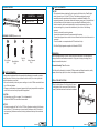
PACKAGE CONTENTS
SAFETY INFORMATION
A
A
B
B
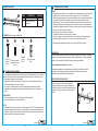
PART DESCRIPTION QUANTITY
A Fixture Plate 1
B Fixture Lens Cover 1
HARDWARE CONTENTS (shown to size)
BB
Drywall Anchor
Qty. 2
SAFETY INFORMATION
AA
Wood Screw
Qty. 2
INSTALLATION INSTRUCTIONS
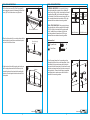
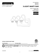
1.Press the bottom frame of the fixture plate (A) inward,
in the direction of the arrows, and lift the fixture lens
cover (B) with the other hand in the direction indicated.
1
Wire Nut
Qty. 3
CC
Linking Connector
Qty. 1
DD
Before beginning assembly of product, make sure all parts are present. Compare parts with
package contents list and hardware contents list. If any part is missing or damaged, do not
attempt to assemble the product.
Estimated Assembly Time: 30 minutes
Tools Required for Assembly (not included): Phillips screwdriver, flathead screwdriver, safety
glasses, electrical tape, pliers, wire cutters, wire strippers, and stepladder.
PREPARATION
Lowes.com
Lowes.com
Please read and understand this entire manual before attempting to assemble, operate or
install the product. Failure to do so could lead to electric shock, fire or other injuries that
could be hazardous or even fatal.
Be sure the electricity to the wires you are working on is shut off. Either remove the fuse or
turn off the circuit breaker.
Changes or modifications not expressly approved by the party responsible for compliance
could void the user’s authority to operate the equipment.
CAUTION:
The fixture lens cover (B) is one piece. Do not disassemble it.
This product CANNOT be used with a dimmer switch.
NOTICE
This device complies with Part 15 of the FCC Rules. Operation is subject to the following
two conditions: (1) This device may not cause harmful interference, and (2) this device
must accept any interference received, including interference that may cause undesired
operation.
•
•
•
•
•
NOTICE
This equipment has been tested and found to comply with the limits for a Class B digital
device, pursuant to part 15 of the FCC Rules. These limits are designed to provide
reasonable protection against harmful interference in a residential installation. This
equipment generates, uses and can radiate radio frequency energy and, if not installed and
used in accordance with the instructions, may cause harmful interference to radio or
television reception, which can be determined by turning the equipment off and on. The
user is encouraged to try to correct the interference by one or more of the following
measures:
Reorient or relocate the receiving antenna.
Increase the separation between the equipment and the receiver.
Connect the equipment into an outlet on a circuit different from that to which the receiver is
connected.
Consult the dealer or an experienced radio/TV technician for help.
This Class B digital apparatus complies with Canadian ICES-003.
•
-
-
-
-
•
Lift up
Press in

4 5
A
A
AA
A
B
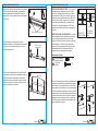
3.Place the fixture plate (A) on a sturdy surface with the
back side facing up and use a screwdriver to punch
out one of the knockout holes.
3
4. Align knockout hole with the supply wire location on
the mounting surface and hold the fixture up in its
intended location with one hand while marking the
location of the two keyhole slots at each end of the
fixture plate.
4
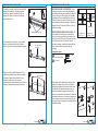
6. Feed the supply wires from the mounting surface
through the knockout hole on the fixture plate. Guide
the heads of the two wood screws into the keyhole
slots and slide the fixture plate (A) in the direction such
that the wood screw heads rest over the narrow part of
the keyhole slot. Ensure that the fixture is supported
and tighten the two wood screws until the fixture is
secured to the mounting surface.
6
INSTALLATION INSTRUCTIONS INSTALLATION INSTRUCTIONS
2.Lift the fixture lens cover (B) off the fixture plate (A)
and unplug the connectors to release the fixture lens
cover (B). Set the fixture lens cover (B) aside.
2
Wood Screw x 2
AA
AA AA
Lowes.com
Lowes.com
Disconnect connectors
Punch through
knockout
(mounting surface)
Mark these
locations
5
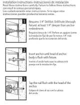
5. DRYWALL MOUNTING: If the mounting holes go
through drywall without a stud, drill two small pilot
holes using a 1/8-in. drill bit (not included), and install
drywall anchors (BB) into the holes with a hammer
(not included). Install the two wood screws (AA) into
the mounting surface but leave about a 3/8-in. gap
between the screw head and mounting surface.
WALL STUD MOUNTING: If the mounting holes go
through wall studs, drill two small pilot holes using a
5/32-in. drill bit (not included) for the wood screws
(AA). Install the two wood screws (AA) into the
mounting surface but leave about a 3/8-in. gap
between the screw head and mounting surface.
Wall Stud
Pilot hole
BB
Drywall Mounting Wall Stud Mounting
Drywall
Hardware Used
Drywall Anchor x 2
BB

6
INSTALLATION INSTRUCTIONS INSTALLATION INSTRUCTIONS
CC
CC
DD
Hardware Used
Wire Nut x 3
Lowes.com
7
Lowes.com
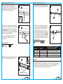
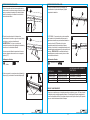
8.Connect the fixture wires to the supply wires --
black to black, white to white, and green to
copper/bare. WARNING: If there is no ground supply
wire, stop installation and consult a qualified
electrician.
Once wire connections are made, secure each with a
wire nut (CC).
8
A
A
A
B
B
9.Re-connect the connectors between the fixture plate
(A) and fixture lens cover (B).
9
Re-connect connectors
7. Remove the heat shrink tubing wrap from the ends of
the black, white, and green wires in order to expose
the copper wires prior to connecting to the building
supply lines.
7
A
DD
Hardware Used
Linking Connector x 1
10. Snap the fixture lens cover (B) back onto the fixture
plate (A) to complete the installation.
10
11. OPTIONAL: If linking two or more fixtures together,
power to each subsequent fixture can be made by
using the linking connector (DD) where only the first
fixture needs to be electrically hardwired and all linked
fixtures only need to be mechanically secured to the
mounting surface. CAUTION: The maximum number
of fixtures allowed to be linked together is indicated in
the following table below.
11
ITEM # MODEL #
MAXIMUM NUMBER OF LINKED FIXTURES
Item # 595682
Item # 595683
Item # 595684
Item # 595685
MXL2005-LED1X10K840
MXL2005-LED1X20K840
MXL2005-LED2X10K840
MXL2005-LED2X20K840
Connect up to 30 fixtures.
Connect up to 15 fixtures.
Connect up to 15 fixtures.
Connect up to 7 fixtures.
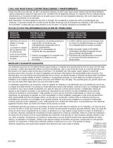
CARE AND MAINTENANCE
Clean with a mild, non-abrasive glass cleaner and soft cloth. Do NOT use solvents or
cleaners containing abrasive agents. When cleaning the fixture, make sure the power is
turned off, and any liquid spray should be applied to the cleaning cloth and not sprayed
directly onto the fixture itself.

8
The manufacturer warrants this lighting fixture to be free from defects in materials and
workmanship for a period of five (5) years from the date of original purchase by the consumer.
We will repair or replace (at our option) the unit in the original color, and style if available, or in a
similar color and style if the original item has been discontinued, without charge, exclusive of
bulbs. Defective units must be properly packed and returned to the manufacturer with a letter of
explanation and your original purchase receipt showing date of purchase. Call
1-866-994-4148
to
obtain a Return Authorization number and an address where to ship your defective product.
Note: No C.O.D. shipments will be accepted. The liability of the manufacturer is in any case
limited to replacement of the defective light fixture product. The manufacturer will not be liable for
any other loss, damage, or injury which is caused by the product. This limitation upon the liability
of the manufacturer includes any loss, damage, or injury which is (I) to person or property or
otherwise; (II) incidental or consequential in nature; (III) based upon theories of warranty,
contract, negligence, strict liability, tort, or otherwise; or (IV) directly or indirectly related to the
sale, use, or repair of the product. This warranty gives you specific rights, and you may also have
other rights which vary from state to state.
WARRANTY
TROUBLESHOOTING
PROBLEM
POSSIBLE CAUSE
CORRECTIVE ACTION
Fixture does not light.
Circuit breaker trips
when light is turned
on.
1. Power is off.
2. Incorrect wire connection.
3. Defective wall switch.
Crossed wires or power wire
is grounded out.
1. Check circuit breaker or wall switch.
2. Check wire splices.
3. Replace switch.
Verify wires are correctly connected.
Lowes.com
Printed in China
Utilitech & UT Design
® is a registered
trademark of LF, LLC. All Rights Reserved.
9
BANDE LUMINEUSE
ARTICLE #0595682, 0595683, 0595684, 0595685
MODÈLE #MXL2005-LED1X10K840
MXL2005-LED1X20K840
MXL2005-LED2X10K840
MXL2005-LED2X20K840
Numéro de série
Date d’achat
Des questions, des problèmes, des pièces manquantes? Avant de retourner l’article au
détaillant, appelez notre service à la clientèle au 1 866 994-4148 , entre 8 h et 18 h (HNE),
du lundi au jeudi, ou entre 8 h et 17 h (HNE) le vendredi.
JOIGNEZ VOTRE REÇU ICI
Lowes.com
Page is loading ...
Page is loading ...
Page is loading ...
Page is loading ...
Page is loading ...
Page is loading ...
Page is loading ...
Page is loading ...
-
 1
1
-
 2
2
-
 3
3
-
 4
4
-
 5
5
-
 6
6
-
 7
7
-
 8
8
-
 9
9
-
 10
10
-
 11
11
-
 12
12
-
 13
13


Utilitech Pro MXL2005-LED1X20K840 Installation guide
- Category
- Serial switch boxes
- Type
- Installation guide
Ask a question and I''ll find the answer in the document
Finding information in a document is now easier with AI
in other languages
Related papers


Other documents
-
 Utilitech UCL24A Installation guide
-
Red Head 35200 Installation guide
-
-
 Red Head 35203 Installation guide
-
Portfolio MXL2007-LED2X34K840 Installation guide
-
 Utilitech 19738-000 Installation guide
-
 Utilitech MXL1043-LED12K9040 Installation guide
-
Project Source CLL56-2WW Installation guide
-
 Style Selections VB256-3BNK Installation guide
-
Origin 21 81010 User manual


