
PWC – 500/1000/1010/1500
PureWaterCooler
Copyright 2006 Vertex Water Products
SERVICE MANUAL
for
PureWaterCooler
™
by Vertex
Model PWC-500/1000/1010/1500
P/N man-7008

PWC – 500/1000/1010/1500
PureWaterCooler
Copyright 2006 Vertex Water Products
Table of Contents
• Introduction
• Cooler Set-up
• Remove Top Cover
• Remove/Replace Float
• Remove/Replace Hot Tank
• Faucet Repair
• Hot Tank Reset Button
• Remove/Replace Hot Tank Thermal Sensors
• Cold Temperature Adjustment
• Drain Cooler Tanks
• Remove/Replace Cold Temperature Switch and Sensor
• Sanitization Procedure
• Trouble Shooting
• PWC-1010 Version
• Specifications
• Cooler Exploded View
•Parts List
• Schematics

PWC – 500/1000/1010/1500
PureWaterCooler
Copyright 2006 Vertex Water Products
PWC-1000 Cooler
1. Introduction
The PWC-1000 line of point of use coolers are designed to give years of reliable service
The cooler has 2 spigots that dispense filtered water at 2 different temperature levels – hot
and cold temperature water. The main (cold-temp) tank holds one gallon of water and is
constructed of stainless steel. The cold tank can be accessed for servicing the float
mechanism and for cleaning by removing the cooler main top cover (see section 4).
The hot tank is made of stainless steel and holds ½ gallon. It is important not to turn on the
hot tank when there is no water in it as this will damage the heating element.
The compressor is a sealed unit and is not serviceable in the field. The compressor can be
replaced by a qualified refrigeration technician with proper tools and equipment.
Please consult the factory if the compressor needs servicing.
CAUTION: If the compressor has been stopped by switching it off or unplugging power,
WAIT 10 MINUTES before turning the compressor on again. The compressor may stall
and burnout if powered back on without waiting.
The cooler makes clean water by filtration or by the reverse osmosis process. Water enters the
back of the cooler and then passes through the filtration system. A feed water ball valve is
Located near the filters and must be turned to the on position to allow the unit to make water.
Electrical power is not required for the cooler to make purified water. CAUTION: The carbon
filtration versions of the cooler (PWC-1000F) should not be used with water hardness over
7 grains because of lime scale build up on the heating element. If hardness is higher than
7 grains, softening of the feed water is recommended or another option is to install
a “phosphate” filter to the filter system.

PWC – 500/1000/1010/1500
PureWaterCooler
Copyright 2006 Vertex Water Products
Feedwater/Drain Connections
-Feed Connection
2.1 Open hinged door to access filter
compartment
2.5 Remove feed water plug (orange) from back
of cooler.
2.6 Connect supplied orange feed water tubing to
feed connector on back of cooler.
2. Cooler Set-Up (for new cooler installation)

PWC – 500/1000/10101500
PureWaterCooler
Copyright 2006 Vertex Water Products
2.4 Make feed water connection to cold water line.
A self piercing saddle valve is provided.
2.5 Flushing carbon fines from carbon filter.
Most carbon filters have fine particles of
carbon material in the filter that will be
swept into the water stream when the first
water flows through the filter. Although not
harmful, these carbon fines in the water are
unsightly. Flush the carbon fines out of the
filter before filling cooler tanks with the
following procedure.
2.6 Remove outlet line of carbon filter (bottom)
2.7 Attach 3 feet of ¼” tubing to the carbon filter
outlet port (flush tubing)
2.8 Place flush tubing in bucket to catch water
carbon fines.
2. Cooler Set-Up cont.
Use supplied self piercing saddle valve.
Connect to water inlet on cooler using 1/4”
tubing. Clamp saddle valve over copper feed
water line (cold water line only). Tighten
needle valve until tube is pierced. Retract
needle 1 -2 turns to start water flow.
Feedwater connection (RO & filtration coolers
(For use on copper tubing)
)

PWC – 500/1000/1010/1500
PureWaterCooler
Copyright 2006 Vertex Water Products
2.9 Turn on feed water at source and turn ball valve
at filter to “on” to let the water flush the filter.
2.10 Flush until water flows clear (1 – 2 gallons)
2.11 Remove flush line. Reconnect tank line to
outlet of carbon filter
2.12 WARNING: Do not turn on cooler hot power
until cooler tanks are full of water.
-Drain Connection
2.9 Drain Connection (for units equipped
with RO)
2.10 Remove drain plug (black) from back of
cooler
2.11 Connect supplied black water tubing to
drain connector on back of cooler
2.12 Attach supplied drain saddle to a
standard 1 ½” drain pipe see fig. 1 below
Drain saddle connection method
Drain connection required only for cooler with reverse osmosis filtration
Figure 1
2. Cooler Set-Up cont.
Figure 2.7
RO filter set showing autovalve.
The autovalve automatically turns off the
water flow when the tanks are full

PWC – 500/1000/1010/1500
PureWaterCooler
Copyright 2006 Vertex Water Products
3.1 Remove (2) screws on back of cooler top cover
3.2 Lift cover
3.3 Cold tank is now accessible for cleaning
and servicing other parts of the cooler.
3.4 Reinstall in reverse order
3. Top Cover Removal

PWC – 500/1000/1010/1500
PureWaterCooler
Copyright 2006 Vertex Water Products
4. Remove/Replace Mechanical Float Valve Assembly
4.1 First, remove top cover. See Section 3
Float Valve/Level Control
4.2 Disconnect tubing from fitting
4.2 Remove elbow connector from float stem

PWC – 500/1000/1010/1500
PureWaterCooler
Copyright 2006 Vertex Water Products
4.3 Remove nut holding float assembly to tank
4.5 Lift out float assembly
continued
Fitting Nut washer Float
Float Assembly Parts
4. Remove/Replace Mechanical Float Valve Assembly

PWC – 500/1000/1010/1500
PureWaterCooler
Copyright 2006 Vertex Water Products
5.0 Unplug power from wall
5.1 Drain water from cooler using front
spigots and by removing rear drain plug
5.2 Remove top cover (section 3)
REMOVE FRONT PANEL
5.3 Remove 2 top screws from front of panel
5.4 Remove 2 screws from bottom of panel.
5.5 Remove 2 screws from back side of front
panel. Requires extra long Phillips-head
screwdriver.
5. Removing/Replacing Hot Tank
5.6 Hold front panel
in hand.

PWC – 500/1000/1010/1500
PureWaterCooler
Copyright 2006 Vertex Water Products
5.7 Disconnect electrical connector at circuit board.
5.8 Hot tank is now accessible
5.9 Remove silicon tubing – 4 places
5.10 Disconnect 2 electrical connectors at bottom
of tank
5.11 Remove (1) hot tank screw from below
• Removing/Replacing Hot Tank
Cont.

PWC – 500/1000/1010/1500
PureWaterCooler
Copyright 2006 Vertex Water Products
5.12 Remove (1) hot tank screw from above.
5.13 Pull hot tank down
5.14 Disconnect (4) electrical connectors
from hot tank temperature sensors.
5.15 Hot tank can now be removed.
5.16 To replace the hot tank, reverse the
above procedure.
• Removing/Replacing Hot Tank
Cont.

PWC – 500/1000/1010/1500
PureWaterCooler
Copyright 2006 Vertex Water Products
6.1 Remove top cover of cooler (section 3)
6.2 For most faucet problems, the working mechanism
of the faucet can be replaced without having to remove
the entire faucet from the cooler. The faucet body
is a one piece molded plastic part that usually does
not need replacing.
6.3 To remove the working mechanism of the faucet, reach
in from the top and unscrew the top nut of the faucet
mechanism.
6.4. Lift out the faucet mechanism from the faucet body.
• Dispensing Faucet Repair

PWC – 500/1000/1010/1500
PureWaterCooler
Copyright 2006 Vertex Water Products
• Faucet Repair
Cont.
6.4 Lift out the lever assembly. Obtain a new
lever assembly and install in the faucet
base. Hand tighten the lever assembly
securely.
6.5 Fill the cooler with water and check for leaks
Note:
When removing and replacing the lever assembly,
make sure the rubber seal and the lever are
connected together. To connect the seal to the lever
assembly, firmly push the seal on to the
button on the lever assembly.
6.6 Reinstall the top panel.
Button Seal
Correctly connected seal/lever assembly
(shown with front panel removed)

PWC – 500/1000/1010/1500
PureWaterCooler
Copyright 2006 Vertex Water Products
7.0 Observe that there are two circular sensors
attached to the hot tank. The lower one is the
main controller at 82 ºC and the upper senor
is the over-temp cut off.
The power switch for the hot tank (at the back
of the cooler) should not be turned on until
water can be dispensed from the hot spigot. If
the hot power is turned on without water in the
hot tank the heating element will over heat. To
prevent this, the upper thermal sensor on the
hot tank will cut power to the heating element
before any damage takes place. If this happens
the switch on the thermal sensor can be reset to
operational mode manually by the following
procedure.
7.1 Make sure the power cord is unplugged.
7.2 From the back of the cooler, find the hot tank
7.3 Find the upper thermal sensor on the hot tank
7.4 Using a long thin object such as a screw driver
or a pen, depress the small black button at the
center of the upper thermal switch. You should
feel a click when you depress the button. This
action resets the over-temp sensor.
7. Hot Tank Reset Button

PWC – 500/1000/1010/1500
PureWaterCooler
Copyright 2006 Vertex Water Products
8. Remove/Replace Thermal Sensor
8.0 The hot tank thermal sensors are located
on the outside of the hot tank. There are
two thermal sensors. The sensor located
lower on the hot tank controls the daily
operation of the heating element. The
upper thermal sensor is an overheat
safety switch and cuts power to the hot
tank should a malfunction occur and
the tank starts to overheat.
8.1 Unplug cooler from power source for
this operation.
8.2 Remove (2) screws holding the upper
part of the cooling grill to the cooler
cabinet. Keep the rubber grommets
for reassembly.
8.3 Carefully pull the cooling grill away
from the cooler. The grill is still attached
at the bottom. Do not move the grill
more than 30 degrees away from the
cooler frame or the cooling system may
be damaged.
30 degrees
Max

PWC – 500/1000/1010/1500
PureWaterCooler
Copyright 2006 Vertex Water Products
8.4 There are (2) thermal sensors attached with
screws to the hot tank. The lower sensor auto-
matically turns the heating element on and off
to maintain the water at 180 ºF. The upper
sensor is the over temperature sensor. This
sensor activates if the temperature on the tank
goes over 212 ºF. If this sensor is activated due
to a overheat condition, it will cut the power to
the heating element. If this happens, it can be
reset by pressing the button at the center of
the sensor.
To check if either thermal sensor is good, use a
continuity tester (ohm meter) to check for
continuity across the thermal sensor. Make
sure the thermal sensor is at ambient temperature
for this test. If there is no continuity, replace
the sensor.
8.5 To change either sensor, disconnect (2)
electrical terminals from sensor.
8.6 Remove (2) screws holding sensor to tank.
8.7 Install new thermal sensor, replace screws,
reconnect electrical terminals to sensor.
8.8 Carefully relocate cooling grill to original
location and re-attach using rubber grommets
and screws.
• Remove/Replace Thermal Sensor
cont.

PWC – 500/1000/1010/1500
PureWaterCooler
Copyright 2006 Vertex Water Products
9.0 The cold water temperature adjustment
is located on the back of the cooler on
the right side. An expansion tube senses
temperature in the cold tank and open
and closes the thermostat.
9.1 The cold adjustment is a shaft with a
screw driver slot on the end.
9.2 To make the water colder, using a
screw driver, rotate the shaft clockwise.
For warmer water rotate the shaft
counter clockwise. There are stops on
the adjustment shaft. DO NOT force
the control shaft over the stop. If this
happens, it will be necessary to replace
the temperature controller
9. Cold Tank Temperature Adjustment
STOP
COLDEST
270º Travel
STOP
WARMEST
Normal Travel is 270º

PWC – 500/1000/1010/1500
PureWaterCooler
Copyright 2006 Vertex Water Products
Completely draining the tanks is required when shipping the cooler
or when one the of the tanks needs replacing. This procedure will
allow you to remove all the water from the cooler.
9.0 Hot and Cold Tank Drain: Using a flat head
screw driver, pry the hot tank plug out until
you can grasp it with your fingers.
9.1 Remove the plug with fingers.
Water will pour from the port
9.2 Drain any remaining water in the
system by depressing the faucets.
10. Draining Cooler Tanks

PWC – 500/1000/1010/1500
PureWaterCooler
Copyright 2006 Vertex Water Products
11. Remove/Replace Cold Tank Sensor
11.0 The cold tank sensor is extremely reliable
and rarely needs replacing. Its function
is to control the cold water temperature by
turning the compressor on or off as needed.
11.1 Remove the top cover of the cooler (sec. 3)
11.2 Remove the float assembly )sec. 4)
11.3 Remove the silicon rubber sealing ring
11.4 Remove the silicon over flow tube
11.5 Carefully lift off the insulting foam
from the cold tank
Page is loading ...
Page is loading ...
Page is loading ...
Page is loading ...
Page is loading ...
Page is loading ...
Page is loading ...
Page is loading ...
Page is loading ...
Page is loading ...
Page is loading ...
Page is loading ...
Page is loading ...
Page is loading ...
Page is loading ...
Page is loading ...
Page is loading ...
Page is loading ...
-
 1
1
-
 2
2
-
 3
3
-
 4
4
-
 5
5
-
 6
6
-
 7
7
-
 8
8
-
 9
9
-
 10
10
-
 11
11
-
 12
12
-
 13
13
-
 14
14
-
 15
15
-
 16
16
-
 17
17
-
 18
18
-
 19
19
-
 20
20
-
 21
21
-
 22
22
-
 23
23
-
 24
24
-
 25
25
-
 26
26
-
 27
27
-
 28
28
-
 29
29
-
 30
30
-
 31
31
-
 32
32
-
 33
33
-
 34
34
-
 35
35
-
 36
36
-
 37
37
-
 38
38


Vertex PWC-500 User manual
- Category
- Water dispensers
- Type
- User manual
Ask a question and I''ll find the answer in the document
Finding information in a document is now easier with AI
Related papers
Other documents
-
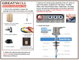 GreatWell ROG400 Installation guide
-
 Hessaire 6020081 Installation guide
-
 Advante H2O Plus Owner's manual
-
Global Water G4 User guide
-
-
-
 Vertex Water Products PureWaterCooler PureChill PWC-9100 Owners & Installation Manual
-
 Avalon A12-CTPOU User manual
-
SUPCO SUPCO-BPV31D User guide
-
 Avalon A9ELECTRICWHT User manual


