Salsbury Industries 3706S-1PARP Installation guide
- Type
- Installation guide

SALSBURY INDUSTRIES
1010 East 62
nd
Street, Los Angeles, CA 90001-1598
Ph: 1-800-624-5269 Int’l Ph: 323-846-6700
Fx: 1-800-624-5299 Int’l Fx:
323-846-6800
Installation instructions are provided as general guidelines. It is advised that a professional installer be consulted. Salsbury Industries assumes no product assembly or installation liability.
Copyright © 2009 Salsbury Industries. All rights reserved. (P/N 370178, Rev. 08, 9/23/09) Page 1 of 5
4C Horizontal Mailboxes – 3700 Series
Single Parcel Lockers
FRONT LOADING and REAR LOADING Installation Instructions
IMPORTANT NOTE FOR FRONT LOADING UNITS !
After installing the unit, contact your local postmaster – the USPS will provide and
install its own master lock on your mailbox unit. Hardware for installing the master
lock is included in the plastic bag.
U.S.P.S. APPROVED
With its high-security design and quality construction, Salsbury’s 3700 series USPS approved 4C horizontal mailboxes and parcel lockers will provide years
of maintenance free service. These units meet all the requirements of USPS-STD-4C, the new high-security standard developed by the United
States Postal Service.
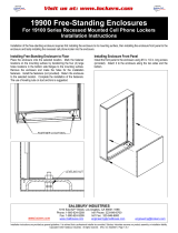
Illustration 1 - Typical Installation
Preparatory Steps
1. Have parcel locker(s) and instructions on hand before starting wall
construction to ensure accurate and tight rough openings.
2. Unpack and review contents of shipping cartons.
3. Gather parcel locker keys and store in a secure place.
4. Read installation instructions document thoroughly.
5. Determine rough opening size(s).
6. Determine rough opening location above finished floor.
7. Determine framing configuration and location.
8. Procure materials for wall construction.
Rough Opening Dimensions
Each unit requires a separate opening in the drywall. If there is more
than one (1) front loading unit, each pair of units will have a 2x4 stud
separating them. See illustration on page 4. If there is more than one
(1) rear loading unit, each pair of units will have a 2x4 stud and two (2)
2x2 studs separating them. See illustration on page 5. The trim frames
will not be butted together. There will be a space between the edges of
the trim frames of approximately ¾” when 2x4 studs with drywall
separate the mailboxes. Inquire at Salsbury for separate instructions for
wall framing to enable butting together of trim frames.
USPS Regulations
The parcel lockers must be installed according to Postal Regulations.
1. The patron lock in the highest parcel locker shall be no more than 67”
above the finished floor.
2. The floor of the lowest parcel locker shall be no less than 15” above
the finished floor.
3. There must be at least one parcel locker for every ten patron
mailboxes in installations of 10 or more patron mailboxes. There is no
requirement for parcel lockers in installations of less than 10 patron
mailboxes, but one or more parcel lockers are recommended.
Calculation of Space Required for Multiple Units
For overall width of parcel locker installation, add all of the 2x4 stud
spacings and subtract ¾”. For overall height of units, see the dimension
chart below on this page.
WIDTHS 1 COLUMN
Overall 16-3/8”
Rough Opening 15-5/8”
Stud Spacing 17-1/8”
HEIGHTS PL5 PL6
Overall 20” 23-1/2”
Rough Opening 19-1/4” 22-3/4”
Wall Construction
Particular attention must be paid to wall framing to provide a strong and
secure attachment of the parcel lockers units. Stud spacing must be
accurate to ensure that there is minimum space between the studs and
the parcel locker frame and minimum parcel locker frame distortion when
the fasteners are tightened between the frame and the studs. Studs
must be installed plumb and square to further ensure proper fit of the
mailboxes.

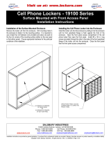
THIS PAGE FOR FRONT LOADING UNITS ONLY.
Parcel Locker Installation
1. Construct wall and parcel locker support structure with drywall,
2x4 lumber, and 3/8” plywood. 2x6 lumber may be used for a
stronger wall. See illustration on Page 4.
2. Cut a hole(s) in the wall according to the rough opening
dimensions. Each parcel locker unit assembly should have its own
opening in the drywall.
3. Open parcel locker door. See illustration below.
Illustration 2 - Door and Trim Frame Location
SALSBURY INDUSTRIES
1010 East 62
nd
Street, Los Angeles, CA 90001-1598
Ph: 1-800-624-5269 Int’l Ph: 323-846-6700
Fx: 1-800-624-5299 Int’l Fx:
323-846-6800
Installation instructions are provided as general guidelines. It is advised that a professional installer be consulted. Salsbury Industries assumes no product assembly or installation liability.
Copyright © 2009 Salsbury Industries. All rights reserved. (P/N 370178, Rev. 08, 9/23/09) Page 2 of 5
4. Open door frame using lockbar by lifting lockbar screws. See
illustration below.
Illustration 3 - Rear View Showing Lockbar Screws
5. Place unit(s) into rough opening(s). Note the mounting hole
locations and drill pilot holes into the studs. Securely fasten to the
framing with the 4 screws provided. See illustration below. Install all
4 screws into the 2 holes provided in each of the right and left side
vertical trim frame members.
Caution: Do not deform, force, or twist the parcel locker frame
to fit an incorrect rough opening or against an irregular surface.
Do not over-tighten the installation screws. If necessary, shim
the small space between the stud and the vertical trim frame
member.
6. Close the door frame into the lockbar with sufficient force to lock.
Caution: Once closed, you will not be able to open the door
frame.
7. Test each parcel locker door to ensure that it opens and swings
freely without binding or sticking.
PARCEL
LOCKER
DOOR
OPEN
Illustration 4 - Fastening Mailbox Unit to Framing
TRIM
FRAME
DOOR
FRAME
O
PEN
RAISE
TWO (2)
SCREWS
TO LIFT
LOCKBAR
PARCEL
LOCKER
OPEN

THIS PAGE FOR REAR LOADING UNITS ONLY.
Parcel Locker Installation
1. Construct wall and mailbox support structure with drywall, 2x2
lumber, 2x4 lumber, and 3/8” plywood. 2x6 lumber may be used in
place of 2x4 lumber for a stronger wall. See illustration on Page 5.
2. Secure the 2 pieces of 2x2 lumber to the wall frame with 16d
penny (3-1/2” long) nails. Space each nail no more than 8” apart,
with the top and bottom nails three (3) inches from each end of the
2x2 lumber.
3. Cut a hole(s) in the wall according to the rough opening
dimensions. Each mailbox unit assembly should have its own
opening in the drywall.
4. Place unit(s) into rough opening(s).
5. Open the parcel door to gain access to the mounting hardware
holes. See illustration 5 on this page. Note the mounting hole
locations and drill pilot holes into the studs. The holes are
approximately 2” in from the front face of the vertical trim frame
members. See illustration 6 on this page. Securely fasten to the
support framing with the #8x2” pan-head torx screws provided.
Install all 4 screws into the 2 holes provided in each of the right and
left side vertical trim frame members.
Caution: Do not deform, force, or twist the frame to fit an
incorrect rough opening or against an irregular surface. Do not
over-tighten the installation screws. If necessary, shim the
small space between the stud and the vertical, extruded-
aluminum trim frame.
6. Test the parcel locker door to ensure that it opens and swings
freely without binding or sticking.
Illustration 5 - Location of Mounting Hardware Holes
Illustration 6 - Fastening Mailbox Unit to Framing
SALSBURY INDUSTRIES
1010 East 62
nd
Street, Los Angeles, CA 90001-1598
Ph: 1-800-624-5269 Int’l Ph: 323-846-6700
Fx: 1-800-624-5299 Int’l Fx:
323-846-6800
Installation instructions are provided as general guidelines. It is advised that a professional installer be consulted. Salsbury Industries assumes no product assembly or installation liability.
Copyright © 2009 Salsbury Industries. All rights reserved. (P/N 370178, Rev. 08, 9/23/09) Page 3 of 5

Illustration 7 - Wall Framing Recommendation for Front Loading Units Only
SALSBURY INDUSTRIES
1010 East 62
nd
Street, Los Angeles, CA 90001-1598
Ph: 1-800-624-5269 Int’l Ph: 323-846-6700
Fx: 1-800-624-5299 Int’l Fx:
323-846-6800
Installation instructions are provided as general guidelines. It is advised that a professional installer be consulted. Salsbury Industries assumes no product assembly or installation liability.
Copyright © 2009 Salsbury Industries. All rights reserved. (P/N 370178, Rev. 08, 9/23/09) Page 4 of 5

Illustration 8 - Wall Framing Recommendation for Rear Loading Units Only
SALSBURY INDUSTRIES
1010 East 62
nd
Street, Los Angeles, CA 90001-1598
Ph: 1-800-624-5269 Int’l Ph: 323-846-6700
Fx: 1-800-624-5299 Int’l Fx:
323-846-6800
Installation instructions are provided as general guidelines. It is advised that a professional installer be consulted. Salsbury Industries assumes no product assembly or installation liability.
Copyright © 2009 Salsbury Industries. All rights reserved. (P/N 370178, Rev. 08, 9/23/09) Page 5 of 5
-
 1
1
-
 2
2
-
 3
3
-
 4
4
-
 5
5


Salsbury Industries 3706S-1PARP Installation guide
- Type
- Installation guide
Ask a question and I''ll find the answer in the document
Finding information in a document is now easier with AI
Related papers
-
Salsbury Industries 4896 User guide
-
Salsbury Industries 19068-18ZSK User manual
-
Salsbury Industries 3621SFU Installation guide
-
Salsbury Industries 3635ZRP Installation guide
-
Salsbury Industries 3621AFU Installation guide
-
-
Salsbury Industries 3600C6-GFP Installation guide
-
Salsbury Industries 3703S-1PGRP Installation guide
-
-
Salsbury Industries 3635ZRP User manual
Other documents
-
Postal Products Unlimited N1029416SND User guide
-
-
-
Gibraltar Mailboxes PL10WW01 Installation guide
-
SereneLife SLMAB06 Owner's manual
-
 Salsbury Cell Phone Locker Enclosure Installation guide
-
 Salsbury Cell Phone Locker Installation guide
-
quadient Parcel P User guide
-
-
Case Logic USP2R Datasheet

