Page is loading ...

11921 Slauson Avenue.
Santa Fe Springs, CA. 90670
(800) 227-4116
TG-150 LMV
TG-20 LMV
INSTALLATION MANUAL
C MAXON Lift Corp. 2000
CONVENTIONAL
LIFTLIFT
LIFTLIFT
LIFT
GAGA
GAGA
GA
TE SERIESTE SERIES
TE SERIESTE SERIES
TE SERIES
M-99-44
REV. 2
APRIL. 2000

LIFT CORP.
11921 Slauson Ave.
Santa Fe Springs, CA. 90670
CUSTOMER SERVICE:
TELEPHONE (562) 464-0099 TOLL FREE (800) 227-4116
FAX: (888) 771-7713
WARRANTY POLICY & PROCEDURE
NOTE: Check with Customer Service for updated versions
of Manuals on an annual basis.
NEW LIFTGATE WARRANTY
Term of Warranty: 2 Years from Date of In-Service
Type of Warranty: Full Parts and Labor
MAXON agrees to replace any components which are found to be defective during the first 2
years of service, and will reimburse for labor based on MAXON’s Liftgate Warranty Flat Rate Labor
Schedule. (Call MAXON Customer Service for a copy).
All claims for warranty must be received within 30 Days of the repair date, and include the
following information:
1. Liftgate Model Number
2. Liftgate Serial Number
3. Detailed Description of Problem
4. Corrective Action Taken, and Date of Repair.
5. Parts used for Repair, Including MAXON Part Number(s).
6. MAXON R.M.A. # and/or Authorization # if applicable (see below).
7. Person contacted at MAXON if applicable.
All warranty repairs must be performed by an authorized MAXON warranty station. For major
repairs, MAXON Customer Service must be notified and an “Authorization Number” obtained. Major
repairs would generally be considered repairs made to the structural assembly of the liftgate and/or
repairs not outlined in the MAXON Liftgate Warranty Flat Rate Schedule.
Major components (i.e. hydraulic pumps, cylinders, valves, or failed structural parts) must be
returned, freight pre-paid, prior to the claim being processed. To ensure timely processing of these
warranty claims, an R.M.A. (Returned Merchandise Authorization) number must be obtained from
MAXON Customer Service prior to the return of any defective part. Defective Parts must be returned
within 60 days of the claim date for consideration to:
MAXON Lift Corp.
16205 Distribution Way, Cerritos, CA 90703
Attn: RMA#__
MAXON’s warranty policy does not include the reimbursement for travel time, towing, vehicle
rental, service calls, oil, batteries, defects due to misuse or abuse, or loss of income due to downtime.
Fabrication of parts, which are available from MAXON, are also not covered.
MAXON’s Flat Rate Labor Schedule takes into consideration the time required for diagnosis of a
problem.
PURCHASE PART W ARRANTY
Term of Warranty: 1 Year from Date of Purchase
Type of Warranty: Part Replacement
MAXON will guarantee all returned genuine replacement parts upon receipt and inspection of
parts and invoice.

Table of Contents
INTRODUCTION ................................................................................... PAGE 4
TRUCK FRAME CUTOUT .................................................................... PAGE 5
CYLINDER LOCK STRAP .................................................................... PAGE 6
PLATFORM INSTALLATION ................................................................. PAGE 7
WELDING LIFTGATE TO VEHICLE ..................................................... PAGE 8
CONTROL SWITCH MOUNTING ....................................................... PAGE 10
POWER CABLE INFORMATION ........................................................ PAGE 11
CONTROL SWITCH GRAVITY DOWN ............................................... PAGE 12
PUMP ENCLOSURE INSTALLATION................................................. PAGE 13
HARNESS & SWITCH ASSEMBLY .................................................... PAGE 14
WIRE CONNECTIONS ....................................................................... PAGE 15
HYDRAULIC ASSEMBLY.................................................................... PAGE 16
BUMPER INSTALLATION ................................................................... PAGE 17
ASSEMBLY OF PLATFORM CLOSER ............................................... PAGE 18
PLATFORM ADJUSTMENT ................................................................ PAGE 19
PLATFORM SHIMING......................................................................... PAGE 20
FIXED RAMP INSTALLATION INSTRUCTIONS ................................ PAGE 21
DECALS .............................................................................................. PAGE 22
SAFETY CHAIN LATCH...................................................................... PAGE 23
LOW VOLTAGE / THERMAL SWITCH (LVTS) ................................... PAGE 24

11921 Slauson Ave. Santa Fe Springs, CA. 90670 (800) 227-4116 FAX (888) 771-7713
PAGE 4
INTRODUCTION
This publication contains the information required to install the following
models and their options:
TG-150 LMV & TG-20 LMV
with 1500 and 2000 pound capacities respectively. If there is doubt regarding
the suitability of these lifts being installed on the vehicle, or any portion of
these instructions that you do not understand, please contact the MAXON
Customer Service Department for consultation.
BEFORE YOU START!
The dimension of the open liftgate platform length must be added to the
body length when considering proper weight distribution on the truck chassis.
In other words, be mindful of the possibility that a loaded liftgate could raise
the front wheels off of the ground.
Unauthorized modification to this equipment may cause failure or create
hazards in it’s use that are not foreseen during installation. These changes
should be discussed with our Engineering Department before being under-
taken.
CAUTION!
Bed height to ground requirements are: 34” Laden to 50” Unladen.
These lifts may be installed on bodies with swing type doors.
Any additional painting on the cylinder rods that retract
beyond the seals, may cause premature failure and will void the
warranty on the cylinders.
Installation of liftgates may obstruct the visibility of existing
conspicuity devices. It is the responsibility of the installer to in-
sure the vehicle meets all conspicuity requirements.

11921 Slauson Ave. Santa Fe Springs, CA. 90670 (800) 227-4116 FAX (888) 771-7713
PAGE 5
TRUCK FRAME CUTOUT
5”
5”
10”
TOP OF VEHICLE FLOOR
VEHICLE FRAME
VEHICLE FRAME

11921 Slauson Ave. Santa Fe Springs, CA. 90670 (800) 227-4116 FAX (888) 771-7713
PAGE 6
CYLINDER LOCK STRAP
1. There are two sets of pin holes for the Cylinder Lock Strap. The shorter
set of holes (23-1/4” center to center), are for bed heights of 40” to 50”
from the ground. (This will be the standard setting from the factory). While
the longer set of holes (24-1/2” center to center), are for bed heights of
34” to 39” from the ground.
2. Verify that the Cylinder Lock Strap is set for the proper bed height prior to
installation.
3. The Cylinder Lock Strap must not be removed until the unit has been
welded to the vehicle, the wiring to the pump has been completed, and the
hydraulic system has been activated to fill the hoses and cylinders under
pressure.
23-1/4”
Factory Setting
Cylinder Lock
Strap

11921 Slauson Ave. Santa Fe Springs, CA. 90670 (800) 227-4116 FAX (888) 771-7713
PAGE 7
Position the Platform onto a stand.
Raise the lifting unit and secure the Shackles
to the Platform with the two (2) Hinge Pins.
Be certain the Torsion Spring is positioned as
shown.
PLATFORM INSTALLATION
260830
Pin, 1 x 6.75”
252685
Pin, 1 x 13.75”
Torsion Spring
Shackle
Weldment
Shackle
Weldment
Lifting Unit

11921 Slauson Ave. Santa Fe Springs, CA. 90670 (800) 227-4116 FAX (888) 771-7713
PAGE 8
WELDING LIFTGATE TO VEHICLE
1.
The Platform should be
centered with the vehicle
bed. Tack Weld 1/2 of the
scrap steel to the Platform.
Let the other half of the flat
rest on the vehicle bed.
C
L
Scrap Steel
Min. 1/4” Thick
x6”Lg.
(Not Provided)
2. Burn a hole in a 1”x 3” Channel.
Weld the Channel on the
centerline of the platform, just
over the pivot holes. Hoist and
Jack the unit into position, with
the rear edge of the Platform as
shown.
CHANNEL
TO P OF VEHICLE
BED
FLOORJACK
HINGE PINS
(SHOULD BE APPROX.
90° TO VEHICLE
FLOOR AS
SHOWN.)
50” MAX.
34” MIN.
Tack Weld
Typ. Both
Sides
Approx. 10”
(Typ.)
NOTE: If a hoist is not available,
a forklift may be used to
support the platform during
this operation.
90°

11921 Slauson Ave. Santa Fe Springs, CA. 90670 (800) 227-4116 FAX (888) 771-7713
PAGE 9
WELDING LIFTGATE TO VEHICLE
VEHICLE FRAME
MOUNT PLATES
1/4
1/4
ALL AROUND
BOTH SIDES
BOTH PLATES
The Mount Plates are shipped with a chassis spacing of 34”. For chas-
sis spacing greater than 34”, burn off the tack welds and re-position the
plates as needed.
IMPORTANT!
Mount Plates are only tack welded when shipped from
the factory. Complete the welds as shown before using.
ALL AROUND
BOTH SIDES
BOTH PLATES
29”

11921 Slauson Ave. Santa Fe Springs, CA. 90670 (800) 227-4116 FAX (888) 771-7713
PAGE 10
CONTROL SWITCH MOUNTING
2.
FLATBED TRUCKS ONLY!
The surface of the side rail
should be at least 2-1/4” tall.
Center the holes in the middle
of the side rail and drill to the
dimensions shown.
Approx.
18”
1.78”
.89”
Drill
.75” Dia.
Drill #21 (.159” Dia.)
(2 Places)
1. The Control Switch will
be mounted on the
vertical post of the
vehicle. The surface of
the vertical post should
be at least 2-1/4” wide
to accomodate the
switch. Center the
holes on the vertical
post to the dimensions
shown.Positioning the
switch on the rear face
of the vertical corner
post may result in the
operators hand being
pinched or crushed by
the closing platform.
Make certain that the
switch is on the outside
of the corner post."
1-1/8” Min.
NOTE: Positioning the switch on
the rear face of the vertical corner
post may result in the operators
hand being pinched or crushed by
the closing platform. Make certain
that the switch is on the outside of
the corner post

11921 Slauson Ave. Santa Fe Springs, CA. 90670 (800) 227-4116 FAX (888) 771-7713
PAGE 11
POWER CABLE INFORMATION
A proper crimp is one which does not have an air gap between the cable
and the copper end fittings after crimping. The crimped end fitting shall not
have any cracks.
Proper sized crimping dies shall be used with a hydraulic or manual
crimping tool. Crimping dies which are struck with a hammer are not accept-
able for initial installation, and should be used only in the case of an emer-
gency repair. Heat Shrink tubing is provided and must be installed at each end
fitting.
CRIMPING
For Trucks, route the cable along the chassis frame flange. Use caution
when routing through or around chassis cross members to avoid sharp edges
which could wear through the cable jacket. MAXON supplies cable installation
clips as shown in Fig. 1.
For Trailers, clamps are provided in the Trailer Kit and can be bolted to
the trailer cross members. This allows the cable to run under the cross mem-
bers. See Fig. 2.
Extra Heavy Duty
Crimping Tool
Never use a Hammer to flatten
the End Fitting when installing
on Power Cable
ROUTING
FIGURE 1
FIGURE 2
2” to 3”
Cable
Clamp
Heat Shrink Tubing

11921 Slauson Ave. Santa Fe Springs, CA. 90670 (800) 227-4116 FAX (888) 771-7713
PAGE 12
CONTROL SWITCH GRAVITY DOWN
Assemble Switch to the vertical post as shown.
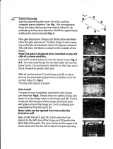
Harness Assembly
P/N 264472
Switch & Cable
Assembly
P/N 264346
To Switch
Decal
P/N 264507
LOWER
RAISE
P/N 264507
Battery Cable Assembly (32’ Std.)
(Includes Replacement Fuse Kit)
P/N 264422
200AMP Replacement Fuse
Kit (P/N 264687)
Short End to
Vehicle Battery
Cable Assembly
Extension Cable Assembly
Long End to Motor
Solenoid
Do not att ach cable to
battery until liftgate is
completely installed.
WARNING
STIKELBACYRETTABELBAILIAVALANOITIDDASTIKELBACYRETTABELBAILIAVALANOITIDDA
STIKELBACYRETTABELBAILIAVALANOITIDDA
STIKELBACYRETTABELBAILIAVALANOITIDDASTIKELBACYRETTABELBAILIAVALANOITIDDA
TRAPTRAP
TRAP
TRAPTRAP
REBMUN
YLBMESSAELBAC'04YLBMESSAELBAC'04
YLBMESSAELBAC'04
YLBMESSAELBAC'04YLBMESSAELBAC'04848462848462
848462
848462848462
YLBMESSAELBACNOISNETXE'01YLBMESSAELBACNOISNETXE'01
YLBMESSAELBACNOISNETXE'01
YLBMESSAELBACNOISNETXE'01YLBMESSAELBACNOISNETXE'01948462948462
948462
948462948462

11921 Slauson Ave. Santa Fe Springs, CA. 90670 (800) 227-4116 FAX (888) 771-7713
PAGE 13
PUMP BOX
COVER
MAINFRAME
PUMP MOUNT
BRACKET
PUMP ENCLOSURE INSTALLATION
Bolt the Pump Box to the Mount Bracket
using (4) 1/2-13 x 1” Soc. Hd. Capscrews
(P/N 900036-5), (4) 1/2” Flat Washers
(P/N 902000-14), and (4) 1/2-13 Nylock
Nut (P/N 901010). Hardware found in
Parts Box.

11921 Slauson Ave. Santa Fe Springs, CA. 90670 (800) 227-4116 FAX (888) 771-7713
PAGE 14
HARNESS & SWITCH ASSEMBLY
Switch & Cable
Assembly
P/N 264346
Harness Assembly
P/N 264472
Switch Boot Seal
P/N 250876
RED
WHT
RED
WHT
YEL
YEL
Switch Gasket
P/N 264589
Screw, self-tapping
#10 x 5/8”
P/N 030453

11921 Slauson Ave. Santa Fe Springs, CA. 90670 (800) 227-4116 FAX (888) 771-7713
PAGE 15
WIRE CONNECTIONS
RED
RED
WHT
YEL
A
B
C
PUMP BOX
GND
FUSE HOLDER
(P/N 263801)
CONNECTOR
(P/N 907021)
MOTOR SOLENOID
SOLENOID
WHT
THERMISTOR
(Part of Motor)
BATTERY
CABLE

11921 Slauson Ave. Santa Fe Springs, CA. 90670 (800) 227-4116 FAX (888) 771-7713
PAGE 16
HYDRAULIC ASSEMBLY
PUMP
PRESSURE
HOSE
PLASTIC RETURN
HOSE
PRESSURE
HOSE
(P/N 263714-01)
PLASTIC
RETURN HOSE
(P/N 905239-01)
ELBOW, BRASS
3/8”NPT x 3/8”TUBE
(P/N 905237)
ELBOW, BRASS
3/8”NPT (M) x 3/8”NPT (F)
(P/N 227004)
PRESS. CNTRL.
VALVE
(P/N 251739)
NOTE:
Do not use liquid sealant
on these fittings
NOTE:
Apply Sealant to
connections per
inside back cover
of this manual

11921 Slauson Ave. Santa Fe Springs, CA. 90670 (800) 227-4116 FAX (888) 771-7713
PAGE 17
BUMPER INSTALLATION
WELD TO VEHICLE,
TOP & BOTTOM
18” (TYP. 2 PLACES)
(Not Used on Flat Bed Installations)

11921 Slauson Ave. Santa Fe Springs, CA. 90670 (800) 227-4116 FAX (888) 771-7713
PAGE 18
ASSEMBLY OF PLATFORM CLOSER
Pushing Arm
Adjust Assembly
201966 Cam
Yoke Roller
261455 &
261474-01
Roller & Brng.
261454
Spacer
Sleeve
040615
3/8-16 x 3” Lg.
030955
3/8-16 Lock
Nut
Pushing Arm
Adjust Assembly
(Same Parts as
Other Side)

11921 Slauson Ave. Santa Fe Springs, CA. 90670 (800) 227-4116 FAX (888) 771-7713
PAGE 19
PLATFORM ADJUSTMENT
The Platform, when properly adjusted, should be in a vertical position
approximately 1” from the Corner Post or “Swing Door” hardware, before
finally closing against the bumpers. If this is not happening, adjust the Plat-
form as follows:
1. Raise the Platform in the open position against
the vehicle.
ON ONE SIDE ONLY, remove the
Roll Pin and Hinge Pin as shown to the right.
2. Use the Hinge Pin to twist the Bolt &
Bushing Weldment in 1/4” increments to
achieve the desired adjustment. Place the
Hinge Pin back into the original configura-
tion without the Roll Pin and lower the Plat-
3. Once this side of the Platform is
adjusted to the desired setting,
replace the Hinge Pin and Roll Pin.
Measure the distance from the end
of the Adjusting Arm to the center
of the Bolt & Bushing Weldment.
Using the same procedure as de-
scribed above, adjust the opposite
side to the same measurement.
form enough to engage the handle to the closing
process. The closed Platform should be vertical and
flush with the bumpers. Repeat if needed.
HINGE PIN
ROLL PIN
HINGE PIN
BOLT &
BUSHING
WELDMENT
“X”
ADJUSTING
ARM
BOLT &
BUSHING
WELDMENT
ADJUSTS TILT
AWAY FROM
BODY.
ADJUSTS TILT
TOWARD BODY.

11921 Slauson Ave. Santa Fe Springs, CA. 90670 (800) 227-4116 FAX (888) 771-7713
PAGE 20
PLATFORM SHIMING
2-1/2” Max.
The Platform should reflect the illustration above
with the tip of the Platform as much as 2-1/2” higher than
the vehicle floor. This dimension will vary, according to
bed height. Before adjusting, check platform at both
upper and lower limit s of travel. If a ramp is attached to
the platform, it should touch the ground.
WELD SHIMS HERE TO ADJUST
PLATFORM TIP UPWARD.
PLATFORM TIP
/