Tatung TLM-43IPC User manual
- Category
- Cable network testers
- Type
- User manual

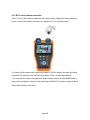
TLM-43IPC
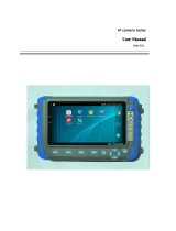
User Manual
4.3” IP / HD Analog / Analog Tester
www.tatungusa.com

Thank you for purchasing the IP camera tester. Please read the manual before using the IP camera
tester and use properly.
For using the IP camera tester safely, please first read the「Safety Information」carefully in the
manual.
The manual should be kept well in case of reference.
Keep the S/N label for after-sale service within warranty period. Product without S/N label will
be charged for repair service.
If there is any question or problem while using the IP camera tester, or damages occurred on the
product, please contact our service department at 1-800-829-2850 ext 216 or email
service@tatungusa.com.

Content
1 Safety information ------------------------------------------------------------------------------------------------------ 3
2 IP Camera Tester Introduction ---------------------------------------------------------------------------------------- 4
2.1 General ------------------------------------------------------------------------------------------------------ 4
2.2 Features ------------------------------------------------------------------------------------------------------ 5
2.3 Function ------------------------------------------------------------------------------------------------------ 7
2.4 Packing list -------------------------------------------------------------------------------------------------- 12
2.5 Function interface ------------------------------------------------------------------------------------------ 13
3. Operation -------------------------------------------------------------------------------------------------------------- 17
3.1 Installing the Battery --------------------------------------------------------------------------------------- 17
3.2 Instrument connection ------------------------------------------------------------------------------------- 18
3.2.1 IP camera connection --------------------------------------------------------------------------- 21
3.2.2 Analog camera connection --------------------------------------------------------------------- 19
3.2.3 HD Coaxial camera connection --------------------------------------------------------------- 20
3.3 OSD menu -------------------------------------------------------------------------------------------------- 221
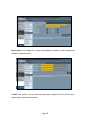
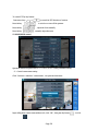
3.3.1 IP discovery --------------------------------------------------------------------------------------- 23
3.3.2 Video monitor test (PTZ control) ------------------------------------------------------------- 25
3.3.3 Color-bar generator (TV OUT) --------------------------------------------------------------- 32
3.3.4 ONVIF --------------------------------------------------------------------------------------------- 33
3.3.5 IP Camera ---------------------------------------------------------------------------------------- 43
3.3.6 SDI Camera ------------------------------------------------------------------------------------- 46
3.3.7 CVI Camera--------------------------------------------------------------------------------------- 47
3.3.8 TVI Camera --------------------------------------------------------------------------------------- 52
3.3.9 AHD Camera
------------------------------------------------------------------------------------ 53
3.3.10 IP address scan ---------------------------------------------------------------------------------- 55
3.3.11 PING Test --------------------------------------------------------------------------------------- 55
3.3.12 Cable test ---------------------------------------------------------------------------------------- 56
Page 1

3.3.13 Port finder --------------------------------------------------------------------------------------- 57
3.3.14 Data monitor ------------------------------------------------------------------------------------ 58
3.3.15 Media Player ------------------------------------------------------------------------------------ 59
3.3.16 Audio player ------------------------------------------------------------------------------------ 60
3.3.17 LED Flashlight --------------------------------------------------------------------------------- 60
3.3.18 PoE/PSE Voltage test -------------------------------------------------------------------------- 61
3.3.19 Calculator ---------------------------------------------------------------------------------------- 62
3.3.20 Browser ------------------------------------------------------------------------------------------ 62
3.3.21 IP camera viewer ------------------------------------------------------------------------------- 63
3.3.22 PoE power / DC12V 2A and DC 5V 2A USB power output -------------------------- 65
3.3.23 Application tools ------------------------------------------------------------------------------- 67
3.3.24 APPS Tools Folder----------------------------------------------------------------------------- 79
3.3.25 System Setting ---------------------------------------------------------------------------------- 80
3.3.26 Update -------------------------------------------------------------------------------------------- 82
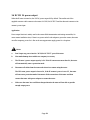
3.4 HDMI output ------------------------------------------------------------------------------------------------ 82
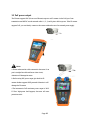
3.5 PoE power output ------------------------------------------------------------------------------------------ 83
3.6 DC12V 2A power output --------------------------------------------------------------------------------- 84
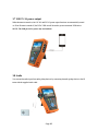
3.7 USB 5V 2A power output -------------------------------------------------------------------------------- 85
3.8 Audio ------ -------------------------------------------------------------------------------------------------- 85
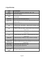
4. Specifications --------------------------------------------------------------------------------------------------------- 86
5. Warranty----------------------------------------------------------------------------------------------------------- 89
Page 2

1 Safety information
The tester is intended to use in compliance with the local rules of the electrical usage and avoid to apply
at the places which are inapplicable for the use of electrics such as hospital, gas station etc.
◆ To prevent the functional decline or failure, the product should not be sprinkled or damped.
◆ The exposed part of the tester should not be touched by the dust and liquid.
◆ During transportation and use, it is highly recommended to avoid the violent collision and vibration
of the tester, lest damaging components and causing failure.
◆Don’t leave the tester alone while charging and recharging. If the battery is found severely hot, the
tester should be powered off from the electric source at once. The tester should not be charged over 8
hours.
◆ Don’t use the tester where the humidity is high. Once the tester is damp, power off immediately and
move away other connected cables.
◆ The tester should not be used in the environment with the flammable gas.
◆ Do not disassemble the instrument since no component inside can be repaired by the user. If the
disassembly is necessary indeed, please contact with the technician of our company.
◆ The instrument should not be used under the environment with strong electromagnetic interference.
◆ Don’t touch the tester with wet hands or waterish things.
◆ Don’t use the detergent to clean and the dry cloth is suggested to use. If the dirt is not easy to
remove, the soft cloth with water or neutral detergent can be used. But the cloth should be tweaked
sufficiently.
Page 3

2 IP Camera Tester Introduction
2.1 General
The 4.3 inch touch screen IP camera monitor and tester is designed for maintenance and installation of
IP camera and analog camera as well as other security equipment, 800x480 resolution enables it to
display network HD cameras and analog cameras in high resolution. The unit supports many ONVIF
PTZ and analog PTZ control. The combination of touch screen and key buttons make the IP camera
tester very user- friendly.
The tester is also a great tool for Ethernet network testing. It can test PoE power voltage, PING, and IP
address searching. You can use the blue cable tracer to locate individual connected cables from a bundle
of cables. Test LAN cable for proper connection termination. Other functions include providing 24W
PoE power to your camera, LED Flashlight, DC 12V 2A power output and much more. Its portability,
user-friendly design and many other functions make the IP tester an essential tool for all installers or
technicians.
Page 4

2.2 Features
4.3inch 800×480 touch screen, easy to operate.
IP discovery, do not need to know the first two digits of camera’s IP address , it can auto-scan
the whole network segment IP, and auto-modify tester’s IP address
Rapid ONVIF, search camera quickly, auto log in and display image from the camera, activate
Hikvision camera.
Hik test tool app is design for activating and debugging Hikvision camera, can auto-identify
unactivated hikvision camera, also can display image from the Hikvision camera.
ONVIF IP camera video testing
Compatible with H.264/MPEG4/MJPEG IP cameras, such as Dahua, HIKVISION, and ACTI
Built in Wi-Fi, can receive image from wireless camera, as well as ONVIF and customized IP
cameras.
SDI Digital camera image display, record and screen snapshot
HD CVI camera image display, zoom ,video record and playback ,coaxial PTZ control and
call camera OSD menu
HD TVI camera image display, zoom ,video record and playback ,coaxial PTZ control and call
camera OSD menu
AHD camera image display, zoom ,video record and playback ,coaxial PTZ control and call
camera OSD menu
HDMI signal output, support 1080P
Analog camera image display, Auto adapt and display the video format of NTSC/PAL
Support more than 30 PTZ protocols ,such as PELCO-P,PELCO-D,SAMSUNG etc
Video image digital zoom to view the image in greater detail.
Snapshot function allows you to save the current image as a JPG file in the SD card.
LED Flashlight.
8GB Micro SD card included.
Page 5

LCD screen brightness/contrast/color Saturation adjustable
Enhanced Color bar generator, PAL/NTSC multi-system color bar video generator
(Eight-system switchable, transmit/receive eight-system colorful images).
In digital IP surveillance applications, if the IP camera’s IP address is not known; the device
cannot be used. An IP address scan can quickly search for the connected IP camera or other
network device’s IP address.
Cable test , Test LAN cable or telephone cable, UTP cable etc ,cable type and the sequence of
wires will be displayed
Support RS232/RS485,Rate 600 ~ 115200bps adjustable
PTZ protocol analysis, control protocol command displays to check RS485 transmission
whether is normal, easy to find the fault device
PTZ control. Pan/tilts the P/T unit, zooms in/out the lens, adjusts the focus, aperture and sets
and the preset position
DC12V 2A output power for camera
PoE 24W power output,supply temporary power for PoE camera
DC5V 2A power output,as a power bank
Audio input and output, test and output the audio signal
7.4V 48.1Wh Battery. Remaining battery charge indicator, Lithium Ion Polymer Battery can
last 16 hours for normal use after charging for 8 hours
Page 6

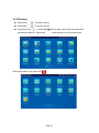
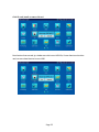
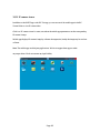
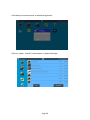
2.3 Function
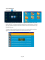
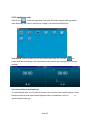
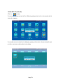
2.3.1 Touch screen and OSD menu
The IP camera tester combines touch screen control and physical buttons. This combination makes the
tester very user friendly. The test meter allows you to move the function icons from the tester’s main
menu to the APPS folder or move them back to customize the main menu
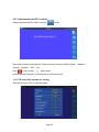
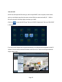
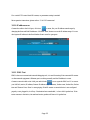
2.3.2 IP discovery
IP discovery, do not need to know the first two digits of camera’s IP address. It can auto-scan the
whole network segment IP, and auto-modify tester’s IP address
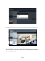
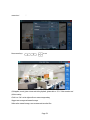
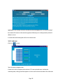
2.3.3 Rapid ONVIF
Rapid ONVIF, search camera quickly, auto log in and display image from the camera, activate
Hikvision camera.
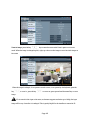
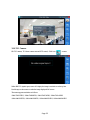
2.3.4 Hik test tool
Hik test tool app is design for activating and debugging Hikvision camera, can auto-identify unactivated
hikvision camera, also can display image from the Hikvision camera.
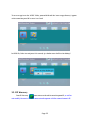
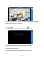
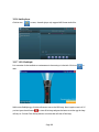
2.3.5 WIFI
With built in WIFI, you can view the video from a wireless camera (ONVIF or customized camera) or
connect to a Wireless network.
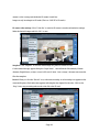
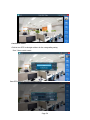
2.3.6 IP camera test
The device is designed for ONVIF IP camera testing. It can display the image from an IP camera and
change the IP address. 4.3 inch 800×480 screen display allows the user to view the image with a
sufficient screen size.
With the ONVIF tool, you can display the image from an IP camera and use the PTZ functions.
Page 7

Currently the IP camera tester supports more than 70 brands’ IP cameras, such as most, ACTi, Dahua,
Hikvision, Samsung, Honeywell and many more
2.3.7 SDI camera test
SDI digital video surveillance testing, support720p 60fps / 1080p 30fps / 1080i 60fps digital camera
image test and video image zoom, record, screen snapshot, photo viewer and video playback.
2.3.8 CVI camera test
HD CVI video surveillance testing, support 720p 25,30,50,60fps / 1080p 25,30fps digital camera image
test and video image zoom, record, snapshot, photo viewer, video playback, coaxial PTZ control and
call up the camera OSD menu
2.3.9 TVI camera test
HD TVI video surveillance testing, support 720p 25,30,50,60fps / 1080p 25,30fps digital camera image
test and video image zoom, record, snapshot, photo viewer, video playback, coaxial PTZ control and
call up the camera OSD menu.
2.3.10 AHD camera test
AHD video surveillance testing, support 720p 25,30fps / 1080p 25,30fps digital camera image test and
video image zoom, record, snapshot, photo viewer, video playback, coaxial PTZ control and call up the
camera OSD menu.
2.3.11 HDMI signal output
The HDMI output port supports up to a 1080p 60Hz resolution output.
2.3.12 Analog camera test
Display analog camera image on 4.3 inch 800×480 LCD screen display, supports PAL & NTSC formats.
The LCD screen's back light brightness, video image brightness, contrast and color saturation are all
adjustable.
2.3.14 PTZ controller
Page 8

Displays and allows for analysis of analog video and controls Pan/tilt/zoom function of PTZ analog
cameras. For PTZ testing, setup the controlling parameters from the meter to match those of the camera:
e.g. PTZ protocol (PELCO-D, etc.), communication port (RS-485, etc.), baud rate, PTZ camera ID and
pan/tilt speed.
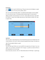
2.3.15 Enhanced Color bar generator
The tester sends out color bars via its BNC output to the monitor. This is used to test for a problem in
the cable going from the camera back to the monitoring area
2.3.16 DC
1
2V 2A power output port and 5VDC 2A USB power port
The unit can power a camera with its 12V DC 2A power output. Also included is a built in 5V DC 2A
power output port used to charge USB devices. NOTE: This USB port is for charging only and has no
ability to transfer data.
2.3.17 PoE power supply
Supports PoE 802.3at power at 48V and up to 24W.
2.3.18 Audio testing
Test the audio from mic level input devices. Connect the tester and mic level device with the audio
cable. Supports audio recording and output to monitor and / or record audio.
2.3.19 PTZ data analysis
Search the Control protocol code from Multifunction keyboard or DVR by RS485 /RS232 interface, test
the PTZ control command data whether received anomaly and RS485/RS232 data transmission.
Screen displays 16 hexadecimal codes such as
PELCO-P:A0 00(Add) xx xxxxxx AF xx
PELCO-D:FF 01(Add)xx xxxxxxxx
2.3.20 Digital Image zooms on the monitor
Set image zoom up to 4X to get a closer look at all the image detail. Supports analog and many IP
cameras
Page 9

2.3.21 Video screenshot
Capture the video image displayed and save as JPEG file in the SD card.
2.3.22 Record
Capture and save the current video in the SD card.
2.3.23 Playback
The recorded files can play directly via Media player or under the function of “Playback”.
2.3.25 DHCP dynamic address assignment
Built in DHCP server: Dynamically assign IP address for the IP camera or network device.
2.3.26 Access the dynamic IP address
The IP tester can directly access a dynamic IP address assigned from its DHCP server and use it as the
tester’s IP address. No need to set the IP address manually.
2.3.27 Multi- segments IP Cameras Test
Support Multi- segment Static IP address setting, which can simultaneously test different segments IP
network cameras.
2.3.28 Network bandwidth testing
The network bandwidth test needs two IP testers to test bandwidth: one as a transmitter, the other as a
receiver.
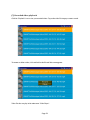
2.3.29 IP address scan
The IP address scan can quickly search for connected IP cameras or another network device IP address.
2.3.30 PING Test
PING is the most conventional network debugging tools. It is used for testing if the connected IP
camera or other network equipment’s Ethernet port is working normally and the IP address is correct.
Page 10

2.3.31 Port Finder
The tester will send signals to make the connected PoE port flicker at a set frequency. This will enable
the installer to easily and quickly find the connected port for an Ethernet cable.
2.3.32 PoE Test
Test the PoE voltage from a PoE switch. The unit will clearly display the voltage for each wire in an
Ethernet cable.
2.3.36 LED Flashlight
Press the LED On/Off button to use the LED flashlight.
2.3.37 Screen image rotates 180 degrees
You can manually rotate the display 180 degrees using the settings.
2.3.39 FTP Server
Start the tester’s Wi-Fi or connect the tester’s LAN port to the network. Once the tester is online, start
its FTP Server and directly access files from the tester’s SD card. This also allows for the user to
upgrade the tester firmware.
Page 11

2.4 Packing list
1) TLM-43IPC
2) Carrying case
3) Shoulder strap
4) Neck strap
5) Network cable tester dongle
6) Adaptor DC12V 2A
7) BNC cable
8) RS485 PTZ control cable with alligator clamp
9) DC Power cable
10) Audio cable with alligator clamp
11) RJ45 cable
12) 8GB SD Card
13) Manual
Page 12

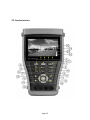
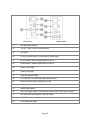
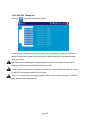
2.5 Function interface
Page 13

1
Press and hold for 2 seconds to turn on or off the device.
Press to turn on or off the menu display
2
Set key
3
Menu key
4
Near focus: Focus the image nearby
5
Far focus: Focus the image faraway
6
TELE: zoom in the image
7
WIDE: zoom out the image
8
Open/set ,Confirm the setting of parameters, open or enlarge the aperture
9
Return/Close : Return or cancel while setting parameters of the menu, close or
decrease the aperture
10
Upward, set function or add parameter. Tilt the PTZ upward
11
Rightward, select the parameter whose value will be changed. Add the value of the
parameter. Pan the PTZ right
12
Confirm key
13
Leftward, select the parameter whose value will be changed
14
Downward, set function or reduce the value of the parameter. Tilt the PTZ
downward
15
Snapshot
16
Record Video
17
Open/set ,Confirm the setting of parameters, open or enlarge the aperture
18
Return/Close : Return or cancel while setting parameters of the menu, close or
decrease the aperture
19 The power indicator: Green when power by power adaptor
20 The RS485/RS232 data received indicator: Red when data is received
Page 14

21 The RS485/RS232 data transmitted indicator: Red when data is transmitted
22
The charger indicator: Red when battery is charging. Off when battery is fully
charged
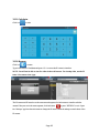
Top interface
Page 15

Left interface Right interface
23 SDI input (BNC interface)
24 "HD IN" , AHD /TVI/CVI Coaxial interface
25 LED lamp
26 DC12V2A power output , for provisional DC power supply
27 RS232 Interface: RS232 communication for the PTZ
28 RS485 Interface: RS485communication for the PTZ
29 Analog Video output
30 Analog Video input
31 Audio and earphone output
32 UTP cable port: UTP cable tester port/ Cable tracer port
33 Micro SD card moveable, supports up to 32GB
34 Audio input
35 HDMI output interface
36 PoE power supply output or LAN test port (Use to test PoE or non-PoE IP camera)
37 PSE power sourcing equipment. Tests PoE voltage
38 DC12V2A
39 5V2A USB power output
Page 16

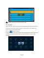
3. Operation
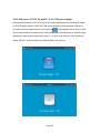
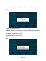
3.1 Installing the Battery
The tester has built-in lithium ion polymer rechargeable battery. The battery cable inside battery
cabin should be disconnected for safety during transportation!
Usually it doesn’t need to disconnect the cable at the normal use
Pressing and hold the key to power on or off the tester.
Notice: Please use the original adaptor and connected cable of the device!
When the battery icon is full or the charge indicator turns off automatically, indicate the battery
charging is completed
When the Charge Indicator turns off, the battery is approximately 90% charged. The
charging time can be extended for about 1 hour and the charging time within 12 hours will not
damage the battery.
Press the key several seconds to restore the default settings when the instrument works
abnormally.
Page 17

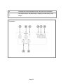
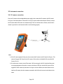
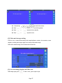
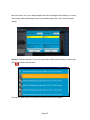
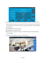
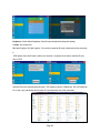
3.2 Instrument connection
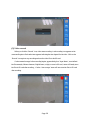
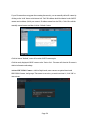
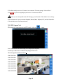
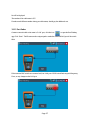
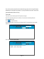
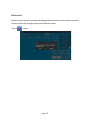
3.2.1 IP camera connection
Power an IP camera with an independent power supply, then connect the IP camera to the IPC tester’s
LAN port, if the link indicator of the tester’s LAN port is green and the data indicator flickers, it means
the IP camera and the IPC tester are communicating. If the two indicators don’t flicker, check if the IP
camera is powered on or the network cable is not functioning properly
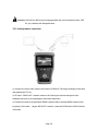
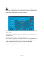
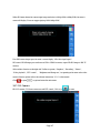
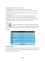
Note:
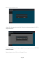
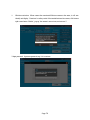
1) If the IP camera requires PoE power, then connect the IP camera to the IP tester’sLAN port . The
tester will supply PoE Power for the IP camera. Click on the icon labeled POE to turn the PoE
Power off or on.
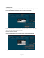
2) If use the tester’s menu to turn off the tester’s PoE power supply, the PoE switch and the power
sourcing equipment are allowed to connect to the tester’s PSE port, and the PoE power will be
supplied to the IP camera by the tester’s LAN port. On this condition, the tester cannot receive
data from IP camera, but the computer connected to the PoE switch can receive the data via the
tester.
Page 18
Page is loading ...
Page is loading ...
Page is loading ...
Page is loading ...
Page is loading ...
Page is loading ...
Page is loading ...
Page is loading ...
Page is loading ...
Page is loading ...
Page is loading ...
Page is loading ...
Page is loading ...
Page is loading ...
Page is loading ...
Page is loading ...
Page is loading ...
Page is loading ...
Page is loading ...
Page is loading ...
Page is loading ...
Page is loading ...
Page is loading ...
Page is loading ...
Page is loading ...
Page is loading ...
Page is loading ...
Page is loading ...
Page is loading ...
Page is loading ...
Page is loading ...
Page is loading ...
Page is loading ...
Page is loading ...
Page is loading ...
Page is loading ...
Page is loading ...
Page is loading ...
Page is loading ...
Page is loading ...
Page is loading ...
Page is loading ...
Page is loading ...
Page is loading ...
Page is loading ...
Page is loading ...
Page is loading ...
Page is loading ...
Page is loading ...
Page is loading ...
Page is loading ...
Page is loading ...
Page is loading ...
Page is loading ...
Page is loading ...
Page is loading ...
Page is loading ...
Page is loading ...
Page is loading ...
Page is loading ...
Page is loading ...
Page is loading ...
Page is loading ...
Page is loading ...
Page is loading ...
Page is loading ...
Page is loading ...
Page is loading ...
Page is loading ...
Page is loading ...
Page is loading ...
Page is loading ...
Page is loading ...
Page is loading ...
Page is loading ...
-
 1
1
-
 2
2
-
 3
3
-
 4
4
-
 5
5
-
 6
6
-
 7
7
-
 8
8
-
 9
9
-
 10
10
-
 11
11
-
 12
12
-
 13
13
-
 14
14
-
 15
15
-
 16
16
-
 17
17
-
 18
18
-
 19
19
-
 20
20
-
 21
21
-
 22
22
-
 23
23
-
 24
24
-
 25
25
-
 26
26
-
 27
27
-
 28
28
-
 29
29
-
 30
30
-
 31
31
-
 32
32
-
 33
33
-
 34
34
-
 35
35
-
 36
36
-
 37
37
-
 38
38
-
 39
39
-
 40
40
-
 41
41
-
 42
42
-
 43
43
-
 44
44
-
 45
45
-
 46
46
-
 47
47
-
 48
48
-
 49
49
-
 50
50
-
 51
51
-
 52
52
-
 53
53
-
 54
54
-
 55
55
-
 56
56
-
 57
57
-
 58
58
-
 59
59
-
 60
60
-
 61
61
-
 62
62
-
 63
63
-
 64
64
-
 65
65
-
 66
66
-
 67
67
-
 68
68
-
 69
69
-
 70
70
-
 71
71
-
 72
72
-
 73
73
-
 74
74
-
 75
75
-
 76
76
-
 77
77
-
 78
78
-
 79
79
-
 80
80
-
 81
81
-
 82
82
-
 83
83
-
 84
84
-
 85
85
-
 86
86
-
 87
87
-
 88
88
-
 89
89
-
 90
90
-
 91
91
-
 92
92
-
 93
93
-
 94
94
-
 95
95


Tatung TLM-43IPC User manual
- Category
- Cable network testers
- Type
- User manual
Ask a question and I''ll find the answer in the document
Finding information in a document is now easier with AI
Related papers
Other documents
-
PSI IP403 Operating instructions
-
Intellisystem IT-C600-IPC Owner's manual
-
Northern IP35TM User manual
-
Stinger SPTG1 User manual
-
 Yuntai IPC-T5 User manual
-
zowieTek How to Control PTZ Camera Operating instructions
-
zowieTek Controlling PTZ Camera Operating instructions
-
 Labgear 50037PI User guide
-
Pelco IP Camera User manual
-
Vitek VT-TC501M User manual

