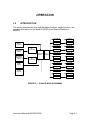
Spectracom 8144-DD User manual
- Category
- Chassis components
- Type
- User manual
This manual is also suitable for

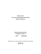
MODEL 8144-DD
Clock Selector/Distribution Amplifier
Instruction Manual
SPECTRACOM CORPORATION
95 Methodist Hill Drive, Suite 500
Rochester, NY 14623
Phone 585.321.5800
Fax 585.321.5219
www.spectracomcorp.com
REVISIONS, IF ANY, ARE LOCATED AT THE END OF THE MANUAL
REVISION A
December 2003
(Model 8144-DD/075020)

5-Year Warranty
SPECTRACOM 95 Methodist Hill Drive Suite 500 Rochester, NY 14623
+1.585.321.5800 FAX: +1.585.321.5218 www.spectracomcorp.com sales@spectracomcorp.com
LIMITED WARRANTY________________________________
Spectracom warrants each new product manufactured and sold by
it to be free from defects in material, workmanship, and
construction, except for batteries, fuses, or other material normally
consumed in operation that may be contained therein, for five
years after shipment to the original purchaser (which period is
referred to as the "warranty period"). This warranty shall not
apply if the product is used contrary to the instructions in its
manual or is otherwise subjected to misuse, abnormal operations,
accident, lightning or transient surge, repairs or modifications not
performed by Spectracom.
The GPS receiver is warranted for one year from date of shipment
and subject to the exceptions listed above. The power adaptor, if
supplied, is warranted for one year from date of shipment and
subject to the exceptions listed above.
The Rubidium oscillator, if supplied, is warranted for two years
from date of shipment and subject to the exceptions listed above.
All other items and pieces of equipment not specified above,
including the antenna unit, antenna surge suppressor and antenna
pre-amplifier are warranted for 5 years, subject to the exceptions
listed above.
WARRANTY CLAIMS________________________________
Spectracom's obligation under this warranty is limited to in-factory
service and repair, at Spectracom's option, of the product or the
component thereof, which is found to be defective. If in
Spectracom's judgment the defective condition in a Spectracom
product is for a cause listed above for which Spectracom is not
responsible, Spectracom will make the repairs or replacement of
components and charge its then current price, which buyer agrees
to pay.
Spectracom shall not have any warranty obligations if the
procedure for warranty claims is not followed. Users must notify
Spectracom of the claim with full information as to the claimed
defect. Spectracom products shall not be returned unless a return
authorization number is issued by Spectracom. Spectracom
products must be returned with the description of the claimed
defect and identification of the individual to be contacted if
additional information is needed. Spectracom products must be
returned properly packed with transportation charges prepaid.
EXCEPT FOR THE LIMITED WARRANTY STATED ABOVE,
SPECTRACOM DISCLAIMS ALL WARRANTIES OF ANY KIND
WITH REGARD TO SPECTRACOM PRODUCTS OR OTHER
MATERIALS PROVIDED BY SPECTRACOM, INCLUDING
WITHOUT LIMITATION ANY IMPLIED WARRANTY OR
MERCHANTABILITY OR FITNESS FOR A PARTICULAR PURPOSE.
Spectracom shall have no liability or responsibility to the original
customer or any other party with respect to any liability, loss, or
damage caused directly or indirectly by an Spectracom product,
material, or software sold or provided by Spectracom,
replacement parts or units, or services provided, including but not
limited to any interruption of service, excess charges resulting from
malfunctions of hardware or software, loss of business or
anticipatory profits resulting from the use or operation of the
Spectracom product or software, whatsoever or howsoever
caused. In no event shall Spectracom be liable for any direct,
indirect, special or consequential damages whether the claims are
grounded in contract, tort (including negligence), or strict liability.
EXTENDED WARRANTY COVERAGE___________________
Extended warranties can be purchased for additional periods
beyond the standard five-year warranty. Contact Spectracom no
later than the last year of the standard five-year warranty for
extended coverage.

8144-DD/075020
TABLE OF CONTENTS
SECTION 1 GENERAL INFORMATION
1.0 INTRODUCTION............................................................................... 1-1
1.1 FEATURES ....................................................................................... 1-1
1.2 WARRANTY INFORMATION AND PRODUCT SUPPORT .............. 1-2
1.3 MANUAL ERRATA AND SPECIAL DOCUMENTATION................... 1-2
1.4 UNPACKING..................................................................................... 1-2
1.5 CONFIGURATION OPTIONS ........................................................... 1-3
1.6 SPECIFICATIONS ............................................................................ 1-3
1.6.1 Inputs ................................................................................ 1-3
1.6.2 Outputs ............................................................................. 1-4
1.6.3 Power Requirements......................................................... 1-4
1.6.4 Mechanical and Environmental Specifications .................. 1-4
1.6.5 Status Indicators ............................................................... 1-5
1.6.6 Operator Controls.............................................................. 1-5
1.6.7 User-Configurable Options................................................ 1-6
1.6.8 Alarm Outputs ................................................................... 1-6
1.6.8.1 Alarm Classification ..................................... 1-6
1.6.8.2 Alarm Interface ............................................ 1-7
SECTION 2 INSTALLATION
2.0 INTRODUCTION............................................................................... 2-1
2.1 PREPARATION FOR USE................................................................ 2-1
2.1.1 AC Line Voltage Selection................................................. 2-1
2.1.2 Power Options................................................................... 2-2
2.2 SWITCH AND HEADER SETTINGS................................................. 2-3

8144-DD/075020
SECTION 3 OPERATION
3.0 INTRODUCTION ...............................................................................3-1
3.1 THEORY OF OPERATION................................................................3-2
3.2 FRONT PANEL FUNCTIONS............................................................3-2
3.3 REAR PANEL CONNECTIONS.........................................................3-4
SECTION 4 OPTIONS
4.1 DC POWER OPTIONS 52 AND 54....................................................4-1
4.2 MOUNTING OPTIONS ......................................................................4-1
4.2.1 Option 11, Rack Mount with Slides ....................................4-1
4.2.2 Option 102, 23/24-inch Rack Mount ..................................4-2
4.2.3 Option 103, Setback Mount ...............................................4-3
SECTION 5 SERVICE INFORMATION
5.0 MAINTENANCE AND CALIBRATION ...............................................5-1
5.1 FUSE REQUIREMENTS ...................................................................5-1

8144-DD/075020
LIST OF TABLES
TABLE 1-1 CONFIGURATION SUMMARY .........................................1-3
TABLE 2-1 SWITCH AND HEADER SETTINGS .................................2-3
TABLE 2-2 OUTPUT LINE LENGTH SWITCH ASSIGNMENTS .........2-8
TABLE 2-3 OUTPUT LINE LENGTH SWITCH SETTINGS..................2-8
TABLE 3-1 CLOCK OUTPUT CONNECTOR PINS .............................3-5
TABLE 4-1 OPTION 11 CHECKLIST...................................................4-1
TABLE 4-2 OPTION 102 CHECKLIST .................................................4-2
TABLE 4-3 OPTION 103 CHECKLIST .................................................4-3
LIST OF ILLUSTRATIONS
FIGURE 2-1 LINE VOLTAGE SELECTION/FUSE REPLACEMENT .....2-2
FIGURE 2-2 MODEL 8144-DD COMPONENT LAYOUT .......................2-4
FIGURE 2-3 8144-DD REAR PANEL.....................................................2-9
FIGURE 2-4 8144-DD FRONT PANEL ..................................................2-9
FIGURE 3-1 MODEL 8144-DD BLOCK DIAGRAM................................3-1
FIGURE 3-2 MODEL 8144-DD FRONT PANEL.....................................3-3
FIGURE 3-3 MODEL 8144-DD REAR PANEL .......................................3-4

SECTION 1 GENERAL INFORMATION
1.0 INTRODUCTION
1.1 FEATURES
1.2 WARRANTY INFORMATION AND PRODUCT SUPPORT
1.3 MANUAL ERRATA AND SPECIAL DOCUMENTATION
1.4 UNPACKING
1.5 CONFIGURATION OPTIONS
1.6 SPECIFICATIONS

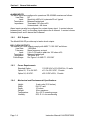
Instruction Manual 8144-DD/075020 Page 1-1
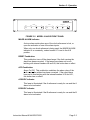
GENERAL INFORMATION
AUTO
MANUAL
ALARMS
READY
INPUT SELECT
Clock Selector/Distribution Amplifier
M
AJOR MINO
R
RESET ACO AB
AB
1.0 INTRODUCTION
Reliable timing in T1 networks is critical. The 8144 Clock Selector/Distribution Amplifier
enhances reliability by providing manual or automatic switchover to a backup system
clock when the primary system clock has failed. The 8144 also provides twelve outputs
for distribution of the selected clock.
1.1 FEATURES
The 8144 Clock Selector/Distribution Amplifier offers the following features:
• Manual or automatic switchover between two clock sources or single input
operation.
• Local and remote alarm indicators, normal or latched, reset from the front
panel.
• Redundant power sources
• Twelve independent outputs.
• DS1 input and output signals.

Section 1: General Information
Page 1-2 Instruction Manual 8144-DD/075020
1.2 WARRANTY INFORMATION AND PRODUCT SUPPORT
Warranty information is found on the leading pages of this manual. Contact Spectracom
Corporation to obtain a replacement or service.
Spectracom continuously strives to improve its products. We greatly appreciate any and
all customer feedback given. Please direct any comments or questions regarding
application, operation, or service to Spectracom's Customer Service Department.
Customer Service is available Monday through Friday from 8:30 A.M. to 5:00 P.M.
Eastern time at 585-321-5800.
Before returning any instrument to Spectracom Corporation, please contact Customer
Service to obtain a Return Material Authorization Number (RMA#). Please provide the
serial number and failure symptoms. Transportation to the factory is to be prepaid by
the customer.
1.3 MANUAL ERRATA AND SPECIAL DOCUMENTATION
Information concerning manual corrections or changes made to the instrument
occurring after the printing of this manual are found on the errata sheet located at the
rear of this manual.
Spectracom sometimes makes instrument modifications upon special request. The
documentation associated with any special modifications is also located in the back of
the manual.
1.4 UNPACKING
Upon receipt, examine the carton and its contents carefully. If there is carton damage
which results in damage to the unit, contact the carrier immediately so its representative
may witness such damage. If you fail to report shipping damage immediately, you may
forfeit any claim against the carrier. You should also notify Spectracom Corporation of
shipping damage or shortages so that we can either help you obtain a replacement or
repair the damaged equipment.
Open the shipping carton carefully and remove the packing list from the envelope on the
outside of the carton. Check the packing list against the contents to be sure all items
have been received, including an Instruction Manual and an ancillary kit.
Retain the carton and packing materials in the event the unit is reshipped or returned to
the factory.

Section 1: General Information
Instruction Manual 8144-DD/075020 Page 1-3
1.5 CONFIGURATION OPTIONS
The Model 8144-DD Clock Selector/Distribution Amplifier can be ordered in a variety of
power and mounting configurations. When specific configurations are referenced in this
Instruction Manual, the format 8144-DD-P-M is used, P and M are the power and
mounting option designations, respectively. The options are listed below in Table 1-1,
Configuration Summary.
Option Type Option Designation
Power
(P)
AC (Standard)
12 to 24 VDC Power
48 VDC Power
(none)
52
54
Mounting
(M)
19" Rack (Standard)
19" Rack with Slides
23/24" Rack
19" Setback Rack
(none)
11
102
103
TABLE 1-1 CONFIGURATION SUMMARY
1.6 SPECIFICATIONS
1.6.1 Inputs
The Model 8144-DD accepts one or two clock inputs as well as one or two alarm inputs.
DS1 CLOCK INPUTS
The DS1 clock inputs comply with ANSI T1.102-1987 as follows:
Line Rate: 1.544 Mb/s
Tolerance: ±130 ppm (200.72 Hz)
Level: 1.0 to 3.6V base-to-peak
Termination: Balanced twisted pair
Impedance: Terminated: 100 ohms ±5%, bridging >1500 ohms
Pulse Shape: Per ANSI T1.102-1987

Section 1: General Information
Page 1-4 Instruction Manual 8144-DD/075020
ALARM INPUTS
The alarm inputs are configured to operate as RS-422/485 receivers as follows:
Line Rate: DC
Level: Sensitivity ±200 mV, hysteresis 50 mV typical
Termination: Balanced twisted pair
Impedance: Terminated 120 ohms ±5%
Unterminated > 4K ohms
Alarm inputs can also be configured for contact closure input. A contact closure
between pins 1 and 3 on the alarm inputs alarms the A channel. A contact closure
between pins 4 and 6 alarms the B channel.
1.6.2 DS1 Outputs
The Model 8144-DD provides up to twelve clock outputs.
DS1 CLOCK OUTPUTS
The twelve DS1 clock outputs comply with ANSI T1.102-1987 as follows:
Line Rate: 1.544 Mb/s
Tolerance: Same frequency as input
Level: 2.4 to 3.6V base-to-peak into 100 ohms ±5%
Termination: Balanced twisted pair
Impedance: 100 ohms ±5%
Pulse Shape: Per Figure 1 of ANSI T1.102-1987
1.6.3 Power Requirements
Standard Option: 115/230 VAC ±15% 50/60 Hz, 15 watts
Option 52, 12 to 24 VDC: ±11.0 to 32.0 VDC, 12 watts
Option 54, 48 VDC: ±55.2 VDC ±20%, 12 watts
1.6.4 Mechanical and Environmental Specifications
Height: 2 rack units (3.50 inches)
Width: EIA 19" rack
Depth: 10 inches
Weight: 6 lbs. maximum
Temperature: 0 to +50°C operating range
Humidity: 95% R. H. non-condensing

Section 1: General Information
Instruction Manual 8144-DD/075020 Page 1-5
1.6.5 Status Indicators
The red MAJOR ALARM lamp is latched on for the following conditions:
LOS Loss of DS1 reference signal on both inputs.
AIS An Alarm Indication Signal on both reference inputs if
AIS is enabled for both inputs.
EXTERNAL ALARM INPUT An External Alarm Input on both alarm inputs.
The red MINOR ALARM lamp is latched for the following conditions:
LOS Loss of DS1 reference signal on one input.
AIS An Alarm Indication Signal on one reference input if
AIS is enabled.
EXTERNAL ALARM INPUT An External Alarm Input on one alarm input.
READY A/B
The green lamps indicate that clock input at A and/or B is available and that the
corresponding alarm input is not activated.
SELECTED A/B
The green lamps indicate that the A or B clock input has been selected.
1.6.6 Operator Controls
RESET: A momentary contact switch that resets latched MAJOR and
MINOR alarms
ACO: A
larm Cut Off. A momentary contact switch that removes the
remote alarm condition (unlatches the alarm relays).
AUTO/MANUAL: Enables automatic switchover or manual selection of references.
PWR Turns power ON or OFF. Switch must be pulled out to toggle.

Section 1: General Information
Page 1-6 Instruction Manual 8144-DD/075020
1.6.7 User-Configurable Options
Various options are configured using internal DIP Switches and headers. These options
are:
• Channel A/B RS-422/485 Alarm Input Termination – selects the termination
impedance for the alarm inputs.
• Channel A/B Clock Input Termination – selects the termination impedance for the
input reference clocks.
• Disable Channel B – for installations where only Channel A input is used.
• Major Alarm Indicator/Relay Latch – selects whether a Major Alarm is latched, or
reported only while the problem condition exists.
• Minor Alarm Indicator/Relay Latch – selects whether a Minor Alarm is latched, or
reported only while the problem condition exists.
• A/B AIS – selects whether the unit recognizes or ignores the Alarm Insertion Signal.
• DS1 Output Framing Mode – selects ESF or D4 framing outputs.
• DS1 Output Line Length Compensation – selects line buildout waveshaping for each
output.
1.6.8 Alarm Outputs
Alarm relays allow remote monitoring of operational status. Relay contacts are provided
for Major and Minor Alarms.
1.6.8.1 Alarm Classification
Major Alarm: A Major Alarm is asserted when detected faults compromise output
function. The outputs are removed during a Major Alarm condition. The latched alarm
relay is reset from the front panel ACO Switch. Faults and conditions listed below
actuate a Major Alarm.
LOS Loss of DS1 reference signal on both inputs.
AIS An Alarm Indication Signal on both reference inputs.
EXTERNAL ALARM INPUT An External Alarm Input on both alarm inputs.
POWER FAILURE External power failure, fuse or internal power supply
failure.

Section 1: General Information
Instruction Manual 8144-DD/075020 Page 1-7
Minor Alarm: A Minor Alarm is asserted when failures detected do not affect output
function. The latched alarm relay is reset from the front panel ACO switch. Faults and
conditions listed below actuate a Minor Alarm:
LOS Loss of DS1 reference signal on one reference input
AIS Alarm Indication Signal on one reference input.
EXTERNAL ALARM INPUT An External Alarm Input on one alarm input.
1.6.8.2 Alarm Interface
Alarm Outputs: Major Alarm, Minor Alarm
Relay Contacts: NO, NC and common.
Contact Rating: 30 VDC, 2 amps
Connector: 7-position terminal block (supplied)

SECTION 2 INSTALLATION
2.0 INTRODUCTION
2.1 PREPARATION FOR USE
2.2 SWITCH AND HEADER SETTINGS

Instruction Manual 8144-DD/075020 Page 2-1
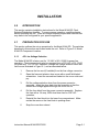
INSTALLATION
2.0 INTRODUCTION
This section contains installation instructions for the Model 8144-DD Clock
Selector/Distribution Amplifier. To ensure proper operation, read this chapter
before operating the unit. There are several internal jumpers and switches that
may have to be configured for your specific application.
2.1 PREPARATION FOR USE
This section outlines the set-up procedure for the Model 8144-DD. The switches
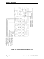
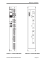
described in this section are located inside the unit. Refer to Figure 2-2, Model
8144-DD Component Location.
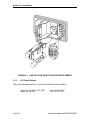
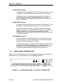
2.1.1 AC Line Voltage Selection
The Model 8144-DD is factory set for 115 VAC ±10%, 50/60 Hz power line
operation. The instrument may also be operated from a 230 VAC ±10%, 50/60
Hz power line. For 230 VAC operation, change the voltage selection drum and
line fuse as illustrated in Figure 2-1, and as described below:
1. Remove the line cord (if installed) from the line voltage connector.
2. Open the fuse and selector drum cover with a small flat-bladed
screwdriver. Insert the screwdriver blade into the cover notch and
pry.
3. Pull the voltage selection drum from the power connector
assembly. Insert the drum back into the assembly so that the
desired line voltage appears through the cover cut-out.
4. Pull the fuse block from the power connector assembly. Replace
the fuse with a 1/4 amp, 250V slow-blow fuse for 230 VAC
operation.
5. Reinstall the fuse block into the lower fuse compartment. Make
certain the arrow on the fuse block is pointing down.
6. Snap the cover door closed.

Section 2: Installation
Page 2-2 Instruction Manual 8144-DD/075020
FIGURE 2-1 LINE VOLTAGE SELECTION/FUSE REPLACEMENT
2.1.2 DC Power Options
Check that the power options on the unit match the power available:
Option 52, 12 VDC to 24 VDC: ±11.0 to 32.0 VDC
Option 54, 48 VDC: ±55.2 VDC ±20%

Section 2: Installation
Instruction Manual 8144-DD/075020 Page 2-3
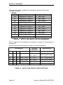
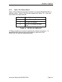
2.2 SWITCH AND HEADER SETTINGS
The switches and headers determine the input alarm and clock termination,
reaction to loss of primary (A) and secondary (B) inputs, the waveshapes of the
DS1 outputs, whether a second clock input is used, and the latching of the alarm
lamps and relays.
A summary of the internal settings is below. A more detailed description follows
on subsequent pages.
HEADER FUNCTION A B
H1 B Alarm Termination High impedance
1
120 ohms
H2 A Alarm Termination High impedance
1
120 ohms
H3 B Clock Termination 100 ohms
1
High impedance /bridging
H4 A Clock Termination 100 ohms
1
High impedance /bridging
H7 B Input Alarm Enable No B Input B Input
1
H8 Major Alarm Indicator Latch Select Latched
1
Not Latched
H9 Minor Alarm Indicator Latch Select Latched
1
Not Latched
H10 Major Alarm Relay Latch Select Latched
1
Not Latched
H11 Minor Alarm Relay Latch Select Latched
1
Not Latched
H14 A Channel AIS Alarm Select Alarm on AIS
1
No Alarm on AIS
H15 B Channel AIS Alarm Select Alarm on AIS
1
No Alarm on AIS
H16 Switching Priority Non-revertive
1
Revertive with A Priority
H17 DS1 Output Framing Select ESF D4
1
SWITCH FUNCTION
S1 “B” Receiver Mode, factory test use only, place all switches OFF
1
.
S2 “A” Receiver Mode, normal operation, place all switches OFF
.1
S3 - S14 Transmit Length Selected, 0-133 feet, Switch 3 ON, Switches 1, 2 and 4 OFF
1
.
S15 Data Output Select Factory Test Framed all one’s
1
1
= Factory setting
TABLE 2-1 SWITCH AND HEADER SETTINGS SUMMARY
Refer to Figure 2-2, Component Layout, to locate and identify functions of the
internal switches and jumpers.

Section 2: Installation
Page 2-4 Instruction Manual 8144-DD/075020
FIGURE 2-2 MODEL 8144-DD COMPONENT LAYOUT

Section 2: Installation
Instruction Manual 8144-DD/075020 Page 2-5
Remove the top cover of the unit to configure the internal jumpers and switches
as follows:
Header Position
H1 B Alarm Input Termination
B Terminates the B Alarm RS-422/485 input with
120 ohms between terminals 4 and 5.
A Removes the 120-ohm termination from the B Alarm input. This
position may be used as an RS-422/485 input between
terminals 4 and 5, or a relay closure between terminals 4 and 6.
Use position B-C unless RS-422/485 input line needs
termination. If relay closure input is used, the header must be in
the B-C position.
H2 A Alarm Input Termination
B Terminates the A Alarm RS-422/485 input with 120 ohms
between terminals 1 and 2.
A Removes the 120-ohm termination from the A Alarm input. This
position may be used as an RS-422/485 input between
terminals 1 and 2 or a relay closure between terminals 1 and 3.
Use position B-C unless RS-422/485 input line needs
termination. If relay closure input is used, the header must be in
the B-C position.
H3 B Clock Termination
A Terminates the B Clock input at terminals 4 and 5 with
100 ohms for DS1 input.
B Removes the terminating resistor for high-impedance input at
terminals 4 and 5 for bridging applications.
H4 A Clock Termination
A Terminates the A Clock input at terminals 1 and 2 with 100
ohms for DS1 input.
B Removes the terminating resistor for high-impedance input at
terminals 1 and 2 for bridging applications.

Section 2: Installation
Page 2-6 Instruction Manual 8144-DD/075020
Header Position
H7 B Input Alarm Enable
A If the 8144-DD is used with only an A clock input, connecting A
to B on header H7 disables the alarm inputs for the B clock
input. Loss of the A reference or the assertion of the A Alarm
input now results in a major alarm.
B This is the normal connection using two clock input signals.
A Major Alarm exists when both references are not ready (AIS or LOS), or when
both external alarm inputs are asserted. A Minor Alarm exists when one of the
references is not ready (AIS or LOS), or when a single external alarm input is
asserted.
Header Position
H8 Major Alarm Indicator Latch Select
A The MAJOR ALARM INDICATOR on the front panel is latched
on by a Major Alarm. A Major Alarm exists when both
references are not ready (AIS or LOS), or when both external
alarm inputs are asserted. The indicator is reset by the RESET
switch if either fault is no longer present.
B The MAJOR ALARM INDICATOR on the front panel does not
latch. The indicator is ON only when a Major Alarm is present.
The light extinguishes automatically when the condition clears.
The RESET switch does not reset the indicator.
H9 Minor Alarm Indicator Latch Select
A The MINOR ALARM INDICATOR on the front panel is latched
on by a Minor Alarm. A Minor Alarm exists when one of the
references is not ready (AIS or LOS), or when a single alarm is
asserted. The indicator is reset by the RESET switch if the fault
is no longer present.
B The MINOR ALARM INDICATOR on the front panel does not
latch. The indicator is ON only when a Minor Alarm is present.
The light extinguishes automatically when the condition clears.
The RESET switch does not reset the indicator.
H10 Major Alarm Relay Latch Select
A The MAJOR ALARM RELAY is latched on by a Major Alarm. A
Major Alarm exists when both references are not ready (AIS or
LOS), or when both external alarms are asserted. The relay is
reset by the ACO switch, even though the fault may still be
present.
B The MAJOR ALARM RELAY does not latch. A remote indicator
shows only if the fault is present. The ACO switch does not
clear the MAJOR ALARM relay.
Page is loading ...
Page is loading ...
Page is loading ...
Page is loading ...
Page is loading ...
Page is loading ...
Page is loading ...
Page is loading ...
Page is loading ...
Page is loading ...
Page is loading ...
Page is loading ...
Page is loading ...
Page is loading ...
Page is loading ...
Page is loading ...
Page is loading ...
Page is loading ...
-
 1
1
-
 2
2
-
 3
3
-
 4
4
-
 5
5
-
 6
6
-
 7
7
-
 8
8
-
 9
9
-
 10
10
-
 11
11
-
 12
12
-
 13
13
-
 14
14
-
 15
15
-
 16
16
-
 17
17
-
 18
18
-
 19
19
-
 20
20
-
 21
21
-
 22
22
-
 23
23
-
 24
24
-
 25
25
-
 26
26
-
 27
27
-
 28
28
-
 29
29
-
 30
30
-
 31
31
-
 32
32
-
 33
33
-
 34
34
-
 35
35
-
 36
36
-
 37
37
-
 38
38


Spectracom 8144-DD User manual
- Category
- Chassis components
- Type
- User manual
- This manual is also suitable for
Ask a question and I''ll find the answer in the document
Finding information in a document is now easier with AI
Related papers


Other documents
-
 Orolia 8144-RD User manual
-
 Orolia 8144-RE User manual
-
 Orolia 8144-RR User manual
-
 Orolia 8144-EE User manual
-
 Orolia 8140MT User manual
-
 Orolia 8143 User manual
-
 Orolia GPS Ageless Master Oscillator 8194B, 8195B, 8197B User manual
-
 Orolia 8165 WWVB Disciplined Oscillator User manual
-
 Orolia 8195A GPS Ageless Oscillator User manual
-
 Orolia 8164 WWVB Disciplined Oscillator User manual


