
Innovative Measurement Electronics
PT112LC,
PT112LC-MB
Load Cell
Weight Transmitter
Instruction Manual Rev. 20210826

CONTENTS
Table of Contents
1 SAFETY................................................................1
2 DESCRIPTION.....................................................2
2.1 INTRODUCTION...................................................2
2.2 DEFINITIONS........................................................2
2.3 FEATURES............................................................2
3 SPECIFICATIONS................................................3
3.1 GENERAL..............................................................3
3.2 DIGITAL SECTION................................................3
3.3 ANALOGUE INPUT...............................................3
3.4 OUTPUTS/INPUTS...............................................3
3.5 SETUP AND CALIBRATION.................................3
4 INSTALLATION....................................................4
4.1 GENERAL RULES.................................................4
4.2 INSTALLATION AND CONTROLS........................4
4.3 CONNECTING THE LOAD CELL..........................5
4.4 CONNECTING THE ANALOGUE OUTPUT..........5
4.5 SETTING ANALOUGUE OUTPUT TYPE.............6
4.6 ENERGISING THE INSTRUMENT.......................6
4.7 ZERO AND SPAN (GAIN) ADJUSTMENT............6
4.7.1 Adjusting with rotary switches.......................6
4.7.2 Fast adjustment to the nominal range..........7
4.7.3 Adjustment at the PLC..................................8
4.8 SET POINT CONFIGURATION.............................8
4.9 DIGITAL INPUT for ZEROING..............................8
4.10 CONFIGURATION BY RS-232C.........................8
4.11 CONFIGURATION WITH AzComT...................10
4.12 TESTING PERFORMANCE..............................10
5 OPERATION.......................................................11
6 TROUBLE SHOOTING.......................................11
7 SERIAL DATA....................................................12
7.1 CONTINUOUS DATA OUTPUT..........................12
7.2 MODBUS COMMUNICATIONS...........................13
7.2.1 Modbus RTU Data Structure.......................13
7.2.2 Frequently used programming steps..........13
7.2.3 Exception codes.........................................14
7.2.4 Command Examples...................................14
8 CONFORMITY....................................................15
Always check the PT web site for the most up to date information and revisions
www.ptglobal.com

www.ptglobal.com PT112LC Instruction Manual 1
1 SAFETY
Safety Statement
CAUTION! READ THIS MANUAL BEFORE OPERATING OR SERVICING THIS EQUIPMENT.
FOLLOW THESE INSTRUCTIONS CAREFULLY. SAVE THIS MANUAL FOR FUTURE
REFERENCE. DO NOT ALLOW UNTRAINED PERSONNEL TO OPERATE, CLEAN,
INSPECT, MAINTAIN, SERVICE, OR TAMPER WITH THIS EQUIPMENT. ALWAYS
DISCONNECT THIS EQUIPMENT FROM THE POWER SOURCE BEFORE CLEANING OR
PERFORMING MAINTENANCE. CALL PT LTD. FOR PARTS, INFORMATION, AND
SERVICE.
WARNING! ONLY PERMIT QUALIFIED PERSONNEL TO SERVICE THIS EQUIPMENT.
EXERCISE CARE WHEN MAKING CHECKS, TESTS AND ADJUSTMENTS THAT MUST BE
MADE WITH POWER ON. FAILING TO OBSERVE THESE PRECAUTIONS CAN RESULT IN
BODILY HARM.
WARNING! FOR CONTINUED PROTECTION AGAINST SHOCK HAZARD CONNECT TO
PROPERLY GROUNDED OUTLET ONLY. DO NOT REMOVE THE GROUND PRONG.
WARNING! DISCONNECT ALL POWER TO THIS UNIT BEFORE REMOVING ANY
CONNECTION, OPENING THE ENCLOSURE OR SERVICING.
WARNING! BEFORE CONNECTING/DISCONNECTING ANY INTERNAL ELECTRONIC
COMPONENTS OR INTERCONNECTING WIRING BETWEEN ELECTRONIC EQUIPMENT
ALWAYS REMOVE POWER AND WAIT AT LEAST THIRTY (30) SECONDS BEFORE ANY
CONNECTIONS OR DISCONNECTIONS ARE MADE. FAILURE TO OBSERVE THESE
PRECAUTIONS COULD RESULT IN DAMAGE TO OR DESTRUCTION OF THE EQUIPMENT
OR BODILY HARM.
CAUTION! OBSERVE PRECAUTIONS FOR HANDLING ELECTROSTATIC SENSITIVE
DEVICES.
Rights and Liabilities
No part of this publication may be reproduced, stored in a retrieval system, or transmitted in any form or by
any means, mechanical, photocopying, recording, or otherwise, without the prior written permission of PT
Limited.
No patent liability is assumed with respect to the use of the information contained herein. While every
precaution has been taken in the preparation of this manual, PT assumes no responsibility for errors or
omissions. Neither is any liability assumed for damages resulting from the use of the information contained
herein.
The information herein is believed to be both accurate and reliable. PT, however, would be obliged to be
informed if any errors occur. PT cannot accept any liability for direct or indirect damages resulting from the
use of this manual.
PT reserves the right to revise this manual and alter its content without notification at any time.
Neither PT nor its affiliates shall be liable to the purchaser of this product or third parties for damages, losses,
costs, or expenses incurred by purchaser or third parties as a result of: accident, misuse, or abuse of this
product or unauthorized modifications, repairs, or alterations to this product, or failure to strictly comply with
PT operating and maintenance instructions.
PT shall not be liable against any damages or problems arising from the use of any options or any
consumable products other than those designated as Original PT Products.
NOTICE: The contents of this manual are subject to change without notice.
All rights reserved. Copyright © 2015 by PT Limited, Auckland, New Zealand

www.ptglobal.com PT112LC Instruction Manual 2
2 DESCRIPTION
2.1 INTRODUCTION
The PT112LC is a DIN rail mounted micro-controller based analogue load cell transmitter with 2 set-
point relays, more analogue output options and programming by serial RS-232C. They have very high
accuracy and long term stability with their high-tech design.
The PT112LC with it’s fast response, higher stability, remote zero and 6 wire input for up to 8x 350Ω
load cells is a higher performing version of the PT111LC.
The PT112LC-MB, as identified on the silver product label on the side, also has -10V to +10V in
place of 0-5V and Modbus communications or serial output.
Using an up to-date delta-sigma ADC and 16 bit DAC to achieve a higher speed and accuracy this
instrument gives the system designers a lot of advantages for increasing system reliability and reducing
installation and service times. All instruments’ analogue outputs are matched during production to
simplify calibration with a PLC and to simplify exchanging the instrument without recalibration in service
when initial adjustment has been performed in the PLC.
There are 8 position rotary switches and annunciator LEDs on the front panel of the instrument. The
upper rotary switch is for making adjustments and the lower rotary switch selects the parameter for
adjustment.
2.2 DEFINITIONS
ADC:
Analogue to digital converter, converts the analogue signal into a digital signal.
DAC:
Digital to analogue converter, converts the digital signal to an analogue signal, usually after some digital
signal processing.
Dead weight:
Dead weight is the self weight of the platform or scale load carrying structure on the load cells without
the contents or items to be weighed. The output voltage of the load cell in response to the weight of the
platform is usually the zero offset. The zero offset must be within the range of the instrument adjustment
for correct operation.
Live weight :
The weight that is applied to the scale and shown on the indicator.
Excitation voltage:
The voltage that is supplied by the indicator to the load cell.
Load cell:
Load cell is a device that converts force to electronic voltage. A load cell consists of two parts. The first
part is a sensor that can be linearly distorted according to the force applied to it. The second part is the
strain gauge element which changes its resistance according to the distortion of the sensor.
The output voltage from the load cell divided by the excitation voltage at load cell rated capacity is the
load cell rated output. This is usually expressed in mV/V.
Input range:
The maximum range of input that the device can accept. This is usually stated in mV and for a full load
cell system is calculated from the number of load cells (Lcn), mV/V (LCmv) and capacity (LCcap) and
also the maximum total load (TL) (including dead load) on the load cells and the excitation voltage (EV).
Input Range (mV) = TL / (LCn * LCcap) * LCmv * EV
Note: A summing box with corner adjustment will reduce this value slightly.
FSO:
Full scale output. Errors may be presented as a % of the full output range after calibration.
2.3 FEATURES
•Minimized zero and span drifts due to use of microcontroller technology.
•High accuracy, very low temperature drift 24 bit ADC and 16 bit DAC converters.
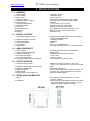
•Compact DIN rail mounting, size is only 22.5mm × 99mm from the front.
•Long term stability and low temperature drifts eliminate the need for the frequent readjustment.
•Adjustable digital adaptive anti-vibration filter to minimize environmental vibrations.
•All instrument have outputs pre-calibrated to 0–10 V, 0-5V, 0-20mA and to 4–20mA analogue
output ranges for 0–2mV/V load cell signal range as a factory default.
•Factory matching facilitates enable swap out without PLC readjustment.
• VCal, calibration without calibration weights (using load cell mV/V entry).
• Programmable with PC, PLC and AzCom software via RS-232C.
•2 free relay contact outputs for setpoints.
•-10V to +10V and Modbus output for the PT112LC-MB

www.ptglobal.com PT112LC Instruction Manual 3
3 SPECIFICATIONS
3.1 GENERAL
1. Power supply : 12-28VDC, 200mA
2. Span stability : <0.005% FSO/ºC
3. Non-linearity : <0.01% FSO/ºC
4. Response speed : 25ms fastest, determined by filter setting
5. Isolation (Input to Output) : Common ground connection (VDC, GND).
6. EMC Immunity : Class E2
7. Operating temperature : -10ºC to 45ºC (14ºF to 113ºF)
8. Relative Humidity : 85% RH max. (non-condensing)
9. Enclosure : Polyamide, DIN-rail mount, IP20
10.Dimensions (mm) : Front Width:22.5 x Height: 99, Depth:114.5
11.Mounting : DIN rail 35 mm x 7.5 mm, DIN 46277-3
12.Weight : Approx 0.45 kg
3.2 DIGITAL SECTION
1. Analogue to digital converter : Ratiometric 24 bit delta sigma ADC with integral
analogue and digital filters
2. Digital to analogue converter : 16 bit low drift DAC
3. Internal resolution : 16000000
4. External Resolution : 65000
5. Annunciators : Run, Current/voltage, Error
6. Digital Filter : 9 settings, adjusted via PC, PLC and with AzCom
3.3 ANALOGUE INPUT
1. Load cell type : All strain gauge load cells and transducers
2. Load cell supply (excitation) : 5VDC, 60mA
3. Number of load cells : 8x 350Ω,16x 700Ω (minimum 43Ω)
4. Analogue input range : -18 to +18mV
5. Zero point adjustment : -18mV to +18mV
6. Span (gain) adjustment for full output : From 0.16mV/V to 3.6mV/V input
3.4 OUTPUTS/INPUTS
1. Analogue Output format : Select from 4-20mA, 0-20mA, 0-10V, 0-5V
: -10V to +10V replaces 0-5V on the PT112LC-MB
2. Maximum load resistance (4 to 20mA) : 500Ω
3. Maximum cable length : 300m (site dependent)
4. Digital Set-points : 2 free contact relay outputs. 230VAC, 30VDC, 1A
5. Digital inputs : PT112LC has 1 opto-isolated input for zeroing
6. Serial data (PT112LC-MB only) : Continuous data, Modbus
3.5 SETUP AND CALIBRATION
1. Setup : Front panel controls and with PC, PLC and
AzComT software
2. Calibration : Performed with rotary switches on the front of the
instrument. With PC, PLC or AzComT, can be
performed without calibration weights.

www.ptglobal.com PT112LC Instruction Manual 4
4 INSTALLATION
4.1 GENERAL RULES
Warning: Please take care to note the following warnings for design of the control cabinet to maximise
system reliability.
The control cabinet should be designed so that the instrument can operate safely. The panel should be
placed in a clean area, away from direct sun light if possible, with a temperature between -10 ºC and
+40 ºC, humidity not exceeding 85% RH non-condensing. All external cables should be installed safely
to avoid mechanical damage.
The PT112LC instruments are very low level signal measuring instruments. To avoid electrical noise,
the transmitters should be separated from any equipment that produces electrical noise. It is preferable
use a metal cabinet to protect against radio frequency interference and the cabinet must be connected
to ground to protect against electromagnetic disturbances. Load cell cable and analogue output cable
trays must be separated from other cables, if possible. If there is noise-generating equipment such as
heavy load switches, motor control equipment, inductive loads etc., please be careful to protect against
EMC interference in the cabinet. Connect parallel reverse diodes to the DC inductive loads like relays,
solenoids etc. to minimize voltage peaks on the DC power lines.
All load cell and analogue output cables coming into and out of the control cabinet must be shielded.
Warning: Control cabinet design and proper installation increases reliability and performance of the
instrument. Please do not forget that the instrument must be powered off before inserting or removing
any peripheral connector or cables.
Follow the installation and commissioning steps described below carefully to prevent unwanted results
after installation.
4.2 INSTALLATION AND CONTROLS
Install the PT112LC in a clean dry location, preferably in a cabinet and away from direct sunlight if
possible. The temperature should be between -10ºC and +40ºC with 85% RH maximum, non-
condensing. Install the instrument on the DIN rail in the cabinet taking note of the general rules above.
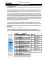
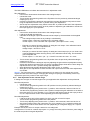
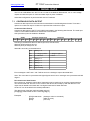
The instrument dimensions are as above, connections are as shown below.
Connections Programming Switch
Pin Name Definition
LOAD CELL CONNECTION
- Ex - Excitation
+ Ex + Excitation
- Si - Signal
+ Si + Signal
+Se + Sense
-Se + Sense
ANALOGUE OUTPUT
I 4 - 20mA output
V 0 - 10V output
G GND
Shield and Protective ground
RS-232C SERIAL CONNECTION
Tx Transmit data, analogue type
Rx Receive data, analogue type
G Serial ground
SETPOINT CONNECTION
O1 Setpoint relay Output 1
O2 Setpoint relay Output 2
Com Setpoint relay common
DIGITAL INPUT (PT112LC only)
+InZ +Input for remote zeroing
-InZ -Input for remote zeroing
POWER SUPPLY
24V +12-28VDC
0V 0VDC
Switch
position
Function
VSelect voltage
output mode 4.5
ISelect current
output mode 4.5
S1 Setpoint 1
adjustment 4.8
S2 Setpoint 2
adjustment 4.8
ZZero adjustment
4.7.1
GGain (span)
adjustment 4.7.1
ZF Fast zero
adjustment 4.7.2
GF
Fast gain setting
with 20% load 4.7.2
Note: G, G and 0V are interconnected with .

www.ptglobal.com PT112LC Instruction Manual 5
4.3 CONNECTING THE LOAD CELL
The load cell wiring should be installed carefully before energizing to avoid damage to the instrument
and load cells. The input resistance of the load cells that you want to connect should be more than the
specification minimum. Do not bind the load cell cables together with other cables as it could result in
cross-talk interference. Please also keep them well away from the AC power cables.
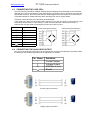
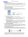
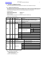
Connect the load cell wires to the terminals as shown below;
If the cable has 4 wires (no sense wires) then connect -Exc to -Sen and +Exe to +Sen at the PT112LC
terminals as shown below. If a junction box is used with load cells with 4 wires best accuracy is
achieved with a 6 wire cable connecting the junction box to the PT112LC.
Pin Name Load Cell Cable 4 wire Load Cell connection 6 wire Load Cell connection
+Ex + Excitation
-Ex - Excitation
+Si + Signal
-Si - Signal
+Se + Sense
-Se - Sense
Shield
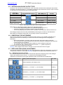
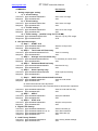
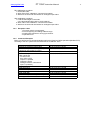
4.4 CONNECTING THE ANALOGUE OUTPUT
Only one of the analogue output types can be used at time and has to be selected in the setup. Install
the analogue output measuring instrument for adjustment, if need be.
Pin Name Definition
ICurrent Output
V Voltage Output
G GND (for V or I)
Shield
Current output connection.
Voltage output connection

www.ptglobal.com PT112LC Instruction Manual 6
4.5 SETTING ANALOUGUE OUTPUT TYPE
On the PT112LC check the Tx and Rx pins, a link connection as below sets its analogue output mode
according to the table at power on. To change the analogue output mode short circuit or open circuit the
Tx and Rx pins of the instrument before connecting power.
Analogue
Output Mode Program Switch Position TXD & RXD pins V/I LED
4 - 20 mA Open circuited On
0 - 20 mA Short circuited Off
0 - 10 VDC Open circuited Flash (~1 per 3s)
0 - 5 VDC (PT112LC-
MB, -10V to +10V) Short circuited Blinking (~1 per s)
Table 1: Annunciator and jumper status during operation.
After power on, the analogue output mode can be changed as follows.
•Turn the lower programming switch to the desired analogue type (V or I).
•Connect or disconnect Tx and Rx according to the above table.
•Turn the top adjusting rotary switch to the ☼ position, wait 2 seconds, and turn it back to “0”.
The analogue output mode can easily be identified by observing the V/I led as in the table above.
After setting your analogue output type you are ready to power on the instrument.
4.6 ENERGISING THE INSTRUMENT
The PT112LC should be connected to a stable DC power source of 12 to 28VDC, preferably try to
avoid electrical noise from switching or motors and check the followings before energising the
instrument.
•Mechanical installation, grounding, load cell connection and power supply connection.
•The Tx and Rx pins on the instrument have been set to specify the analogue output at power
on to be of type V or I as above.
•The analogue output cabling has been installed to suit the analogue output type.
•The adjustment rotary switches have been set at the “ 0 “ position at power on.
If everything is correct energise the instrument.
Warning: If the voltage/current mode is changed, turn the instrument off and on again.
4.7 ZERO AND SPAN (GAIN) ADJUSTMENT
There are two methods of performing zero and span adjustment, either in the transmitter or in the PLC
or instrument to which it is connected. Warning: Setting Zero and Span will fail if the ERR LED is on.
4.7.1 Adjusting with rotary switches.
Zero and Gain adjustment rotary switches are used to adjust zero and gain (span) of the analogue
output. Both switches must be at the “ 0 “ position when the adjustment starts.
Adjustment is performed by turning the adjustment switch as described in the table below.
Rotary switch position Rotary switch description Run LED
Normal operation, No change occurs On
Decrease ( - ) / Increase ( + ) in slow steps Flashing
Decrease ( - ) / Increase ( + ) in medium steps Flashing
Decrease ( - ) / Increase ( + ) in large steps Flashing

www.ptglobal.com PT112LC Instruction Manual 7
The RUN LED flashes to indicate the instrument is in adjustment mode.
Zero Adjustment
•Connect the measurement instrument to the analogue output.
•Unload the scale.
•Turn the lower programming switch to the Z position from the previously selected analogue
output type (V or I).
•Increase or decrease the analogue output with the top zero adjustment rotary switch. Never
bring the adjustment switch to the ☼ position during zero adjustment.
•Set the top zero adjustment rotary switch to be at the “0“ position at the end of the adjustment.
•Set the lower programming switch to the G position to adjust the gain calibration or set back to
the output type (V or I) for operation.
Gain Adjustment
•Connect the measurement instrument to the analogue output.
•Load the scale with the test load.
•Calculate the analogue output value that should be output by the transmitter for the applied
load.
◦The analogue output value at any loading is calculated by;
voltage output = test load / full output load * full output voltage
current output = 4mA + test load / full output load * (full output current – 4mA)
◦Example you want a full scale capacity of 100kg and 10V output. Your calibration load is
25kg. The PT112LC gain is adjusted until;
voltage output = 25/100*10 = 2.5V
◦Example you want a full scale capacity of 200kg and 16mA output (so you can have some
overload allowance before reaching 20mA). Your calibration load is 25kg. The transmitter
gain is adjusted until;
current output = 4 + 25 / 200 * (16 – 4) = 5.5mA For 0-20mA 25 / 200 * 16 = 2mA
•Turn the lower programming switch to the G position from the previously selected analogue
output type (V or I).
•Increase or decrease the analogue output by adjusting the gain with the top adjustment rotary
switch and measure the output until you get the calculated output value above. Never bring the
adjustment switch to the ☼ position during span adjustment.
•After adjustment set the gain adjustment rotary switch to the “ 0 “ position
•After gain or zero adjustment re-check the zero and output under load and make adjustments
as needed.
Warning: The instrument saves 4 different adjustments in its memory for the voltage and current
outputs and their associated ranges. Changing the analogue output type automatically selects any
adjustments previously made for that output range.
4.7.2 Fast adjustment to the nominal range.
If setting zero and gain to nominal ranges suits your application fast adjustment can be performed.
Fast Zero Adjustment
•Unload the scale.
•Turn the lower programming switch to the ZF position from the previously selected analogue
output type (V or I).
•Turn the top adjusting rotary switch to the ☼ position, wait 2 seconds, and turn it back to “0”.
• Set the lower programming switch to the G position to adjust the gain calibration or set back to
the output type (V or I) for operation. For V output this will set the output for the empty scale to
0V, for I output it will be 4mA or 0mA depending upon the output selected.
Fast Gain Adjustment
•Load the scale to 20% of the capacity for which you wish to have full output.
•Turn the lower programming switch to the GF position.
•Turn the top adjusting rotary switch to the ☼ position, wait 2 seconds, and it turn back to “0”.
•Set th lower switch back to the output type (V or I) for operation. For V output this will set the
output for the scale at 100% load to 5 or 10V (depending on configured range), for I output it
will be 20mA.
Example: set the PT112LC for output 4-20mA for 0 to 100kg load.
Configure the PT112LC for 4-20mA output (see 4.5 ), empty the scale, perform fast zero, place 20kg on
the scale and perform fast gain adjustment.

www.ptglobal.com PT112LC Instruction Manual 8
4.7.3 Adjustment at the PLC
All PT112LC instruments are adjusted during production to operate by default to achieve the selected
analogue output range for an input between 0 mV and 10 mV (2mV/V load cell signal).
For example if the instrument is at factory default values and programmed to operate in the 4 – 20 mA
output mode, the output will be 4 mA at 0 mV/V load cell signal and will be 20 mA at 2 mV/V load cell
signal.
If you need to exchange the transmitter for any reason, recalibration is not required because of
instrument matching during production.
4.8 SET POINT CONFIGURATION
The PT112LC has 2 relay contact set points. The relays are rated 240VAC/30VDC, 1A maximum.
Reverse diodes are recommended across the contacts for DC loads to increase relay contact life and
suppress arcing. Set-point connection is as below for the PT112LC.
Adjust setpoint to the load on the scale.
•Load the scale with the load at which you wish the setpoint to switch.
•Turn the lower programming switch to the S1 (or S2) position from the previously selected
analogue output type (V or I).
•Turn the top adjusting rotary switch to the ☼ position, wait 2 seconds, and turn it back to “0”.
• Set the lower programming switch back to the output type (V or I) for operation.
Adjust setpoint by output measurement.
•Connect the measuring instrument (volt or amp meter as appropriate) to the analogue output.
•Turn the lower programming switch to the S1 (or S2) position from the previously selected
analogue output type (V or I).
•Increase or decrease the analogue output with the top adjustment rotary switch. Never bring
the adjustment switch to the ☼ position during adjustment. The switch should be at “0” when
the output is at the value you want the setpoint to switch.
•Set the lower programming switch back to the output type (V or I) for operation.
4.9 DIGITAL INPUT for ZEROING
The PT112LC has a digital input to enable convenient zeroing of the instrument. The input terminal
connections are shown in 4.2 INSTALLATION AND CONTROLS. The input is opto-isolated, accepting
12-28VDC. A simple push button can be implemented by connection -InZ to the power (0V) terminal
and +InZ to the Power (24V) terminal via a normally open push button switch.
4.10 CONFIGURATION BY RS-232C
The PT112LC can be configured by PC or PLC over the RS-232C port. Connection is 3 wire serial and
should be set to 9600 baud, 8 data bits, no parity and 1 stop bit (8N1). Standard software such as
Windows Hyperterminal, Mac OSX Screen and telnet can be used with serial and USB cables from PT.
The structure of the commands and replies are as follows. All characters are the ASCII keyboard
characters except the <CR>. @ character followed by 18 characters followed by 2 characters
checksum followed by <CR> or <CR><LF>. The 4 characters before the checksum represent the
hexadecimal value of any value to be entered, without decimal point. i.e. 4E2F = 2.0015 mV/V

www.ptglobal.com PT112LC Instruction Manual 9
COMMANDS: Descriptions
1. Analog output type setting:
a) 4 - 20 mA setting:
Command : @01100000000102000BE1 Set to 4-20 mA range
Response : @011000000001EE ACK
b) 0 - 20 mA setting:
Command : @011000000001020014D8 Set to 0-20 mA range
Response : @011000000001EE ACK
c) 0 - 10 VDC setting :
Command : @01100000000102000AE2 Set to 0-10 VDC range
Response : @011000000001EE ACK
d) 0 - 5 VDC setting : (±10VDC range for PT112-MB)
Command: @011000000001020013D9 Set to 0-5 (±10) VDC range
Response: @011000000001EE ACK
2. vCal procedure steps:
a) Step 1. START vCal
Command : @011000000001020001EB Start the vCal process.
Response : @011000000001EE ACK
b) Step 2. Total Load cell Emax entry
Command : @01100003000204000001F4F1 Total LC is 500 kg.
Response : @011000030002EA ACK
c) Step 3. Average Load cell mV/V entry
Command : @0110000500020400004E2F67 LC sensitivity is 2.0015 mV/V.
Response : @011000050002E8 ACK
d) Step 4. Estimated Dead load entry
Command : @0110000700020400000000E2 Dead load is 0 kg.
Response : @011000070002E6 ACK
e) Step 5. Scale Capacity entry
Command : @01100009000204000000FAE6 Scale capacity is 250 kg.
Response : @011000090002E4 ACK
f) Step 6. SAVE with estimated dead load value
Command : @011000000001020007E5 Save the vCal values.
Response : @011000000001EE ACK
Or SAVE with automatic zero adjustment.
Unload the scale and send the command below to start the zero adjustment.
Command : @011000000001020015D7 Save the vCal with Zero Adj.
Response : @011000000001EE ACK
g) Step 7. APPLY
Command : @011000000001020009E3 Apply the calibration.
Response : @011000000001EE ACK
h) Step 8. STOP vCal
Command : @011000000001020002EA Stop the vCal process
Response : @011000000001EE ACK
3. Digital Filter Setting:
Command : @011000220001020000CA Set the Fast filter (0)
Command : @011000220001020001C? (9 -2) Set to filter inbetween
Command : @011000220001020002C1 Set to Slow filter (9)
Response: @011000220001CC ACK
4. Load Factory Defaults:
Command : @011000240001025AA5C9 Set to factory default settings.
Response: @011000240001CA ACK

www.ptglobal.com PT112LC Instruction Manual 10
CHECKSUM CALCULATION:
CSUM = 0 – (Slave_Add + Function + … + Last_data)
(STX and CSUM are neglected while calculating CSUM, calculations in Hexadecimal)
Example
For Medium (1) filter: @011000220001020001XX
CSUM = 0 – (01+10+00+22+00+01+02+00+01)
= 0 – 37 = C9
Command is @011000220001020001C9 <CR>
Warning: After configuration by RS-232C ensure that the switches and jumpers are set as in
Table 1: Annunciator and jumper status during operation. to ensure that the PT112LC starts in the
correct mode the next time it is powered on.
4.11 CONFIGURATION WITH AzComT
The PT112LC have an RS-232C serial interface to perform vCal electronic calibration, to adjust
filter and setpoint values and to monitor status by with the use of AzCom software installed on a
PC.
Note: There are 2 versions of the software, AzComT is required for transmitters and should be
installed before following these instructions.
For programming the instrument via AzCom please follow the instructions below;
1. Power off the instrument.
2. Connect the instrument to a PC as shown above in 4.10 to use the AzCom software,
then run AzComT and select the PT112LC and press the “OK” button. If you have a
PT112LC-MB and AzComT select that option.
3. Select the analogue output type required if the default is not suitable.
4. Adjust the filter value if necessary.
5. For vCal, enter total load cell capacity, scale capacity and estimated dead load
(alternatively for a more accurate zero calibration perform fast zero adjustment by clicking
the button on the PC screen while the scale is empty).
6. Press the “Write vCal Data to Transmitter” button on the screen to perform vCal.
7. Unload the scale and Press “ vCal with Zero Adjustment “ button on the PC screen if you
wish to perform zero adjustment from the load cell signal when the scale is unloaded.
8. Power off the instrument, disconnect the PC and bring the lower programming switch to
the analogue output type position (V or I) as require and insert the connecting jumper
between TXD and RXD pins as described in the table in 4.5 , Table 1: Annunciator and
jumper status during operation. to set the analogue output type.
9. Turn the top adjustment switch position to the “0“ position.
10. Power the instrument on for operation.
After performing vCal, check the performance of your system.
You can reset to factory defaults with AzCom if it is necessary to restart from the beginning.
4.12 TESTING PERFORMANCE
Check the scale performance by testing the scale eccentricity, scale linearity with loading up to the
maximum loading value, repeatability, etc. before putting the scale into use.

www.ptglobal.com PT112LC Instruction Manual 11
5 OPERATION
There are 3 LEDs and 2 adjustment rotary switches on the front panel of the PT112LC. The rotary
switches should be at the “ 0 “ position for operation.
In operation rotary switch positions, Tx and Rx pin connections, and LED indication should be as in
Table 1 Annunciator and jumper status during operation.
Refer to the Section TROUBLE SHOOTING in the event the Err LED is on.
The analogue output signal also gives information about the status of the system and the weighing
process and can be interpreted by a PLC to signal an alarm or a need for service as follows;
Condition Current output Voltage output
During Operation As calibrated As calibrated
During Programming As calibrated As calibrated
The weight is more than the maximum range
( Over range signal to the PLC ) 24 mA 11 V
The weight is less than the zero range
(Under range signal to the PLC ) 0 mA -4.0 V
“Error” all signal to the PLC is stopped 0 mA 0 V
“ADC is out of operating range” error to the PLC 24 mA 11 V
6 TROUBLE SHOOTING
The PT112LC transmitters has been designed as a very reliable and virtually error free instruments.
However if an error occurs, do not attempt to repair the equipment before you understand what caused
the error. Note the status of the front panel LEDs, and try to find the problem with the help of the table
given below. Don’t let unauthorised people interfere with the instrument.
Front Panel LEDs
STATUS INDICATION
Run V/I Err
Off Off Off •No power
•Board failure
On On Off •Operation in 4 – 20 mA output mode.
On Off Off •Operation in 0 – 20 mA output mode.
On Flashing Off •Operation in 0 – 10 VDC output mode.
On Blinking Off •Operation in 0 – 5 VDC or ±10V output
mode(PT112LC-MB).
On On or
Flashing On
(For output modes 4–20mA and 0–10VDC)
•Input signal is out of range. Check load cells and
wiring, The error light will be on if the load cell
connection is incorrect, i.e. the PT112LC sense
wires are not connected. Check the installation.
•Check output circuit and cabling. The error light will
be on if the transmitter is powered on in current
mode without a current loop connection.
•Board failure
•Calibration needed. Re-calibrate.
The analogue output also gives additional information about the weighing system as described in
OPERATION.

www.ptglobal.com PT112LC Instruction Manual 12
7 SERIAL DATA
The PT112LC-MB differs from the PT112LC in that it has Modbus, Bidirectional -10V to +10V voltage
outputs and with the option of continuous data output in place of Modbus.
Serial data configuration is performed with AzComT software.
7.1 CONTINUOUS DATA OUTPUT
Continuous data output from the instrument is transmitted in the following data formats. There are 2
options for continuous output. Continuous output and fast continuous output.
Continuous Data Format
Continuous data output of the PT112LC-MB is transmitted in the following data formats. The serial port
of the PT112LC-MB is suitable for bi-directional communication.
CHK (Checksum) can be enabled or disabled.
Status Analogue output value Reserved
STX STA STB STC D5 D4 D3 D2 D1 D0 D5 D4 D3 D2 D1 D0 CR LF CHK
Following is the definition table for status bytes STA, STB and STC;
Status A (STA) is always hex ‘6A’.
Status C (STC) is always hex ‘30’.
Status B is according to the table below.
Bit 0 Always = 0
Bit 1 0 = Weight positive 1 = Weight negative
Bit 2 0 = No Error 1 = Error
Bit 3 Always = 1
Bit 4 Always = 1
Bit 5 Always = 1
Bit 6 Always = 0
Bit 7 X (not used)
Error messages A.OUT and L VOLT will be sent in the Analogue output value data field.
Note: The count data is represented with right aligned and the error messages are represented with left
aligned.
Fast Continuous Data Format
Fast continuous “Analogue output value” data output can be used only for receiving instruments that
can communicate fast. There is no flow control if the device cannot keep up with the data flow. The
output rate is related to the baud rate. Use higher baud rate for faster data rate.
CR and LF can be enabled in the related parameters.
The data format of the fast continuous data output is;
[STX][D][+][ ANALOGUE OUTPUT VALUE ][CR][LF]
Examples :
[STX]D+00012345 (Analogue value is 12.345mA)
[STX]O (ADC out error)
[STX]L (Low volt)

www.ptglobal.com PT112LC Instruction Manual 13
7.2 MODBUS COMMUNICATIONS
The PT112LC-MB transmitter has a Modbus RTU interface over the RS232C serial port.
7.2.1 Modbus RTU Data Structure
After programming the RS232C serial port for Modbus RTU in AzComT, the PT112LC-MB can be used
as a Modbus RTU slave on a Modbus RTU network. Function codes ‘0x03’ (Read Holding Registers),
‘0x06’ (Single Write Register) and ‘0x10’ (Preset Multiple Registers) are supported.
Parameter set-up:
Set the RS232C Data Format : Modbus RTU
RS232C Data Length & Parity : 8 none 1,
RS232C Address : 01 to 31
Please find Modbus information in the web site of http://www.modbus.org
Modbus RTU Command Table;
Address R/W Word Command Definition
40001 R 1 Analogue output
value (Unlimited)
Absolute analog value is indicated with 0.001
increments. For example: 2.341V is indicated as
integer 2341 value.
40002 1 Not used Not used
40003 R 1 Status
D0 0 – Run LED is OFF 1 – Run LED is ON
D1 0 – V/I LED is OFF 1 – V/I LED is ON
D2 0 – Error LED is OFF 1 – Error LED is ON
D3 0 – Output-1 is passive 1 – Output-1 is active
D4 0 – Output-2 is passive 1 – Output-2 is active
D5 Not used
D6
D7 Analogue mode
Dec Description
0 4 - 20 mA
1 0 - 20 mA
2 -10 / +10 VDC
3 0 - 10 VDC
D8 0 – Input-1 is passive 1 – Input-1 is active
D9-D15 Not used
40004 R/W 1 Control
Dec. Description
0 None
1 Zeroing
2 Zero FAST calibration
3 Gain FAST calibration (at %20 FR for PT112LC-MB)
40005 1 Not used Not used
40006 R/W 1 Not used Not used
40007 R/W 1 Set-point-1 This value is indicated with 0.001 increments
as analog output value.
40008 R/W 1 Set-point-2 This value is indicated with 0.001 increments
as analog output value.
40009 R/W 1 Digital Filter
Dec Description
0 Fast
:
5 Medium
:
7 Default
:
9 Slow
7.2.2 Frequently used programming steps
Reading analogue output value:
1. Read 40003 and check D2=0,
2. If D2=0, read 40001,
3. If D2=1, check D2 until D2=0,

www.ptglobal.com PT112LC Instruction Manual 14
Zero Calibration procedure:
1. Unload the scale.
2. Write “Zero FAST calibration” command from 40004.
3. Wait for 5 seconds and read 40001 for analogue output value.
Gain Calibration procedure:
1. Load the test weight on the scale.
a. the test load should be 20% of scale capacity.
2. Write “Gain FAST calibration” command from 40004.
3. Wait for 5 seconds and read 40001 for analogue output value.
7.2.3 Exception codes
1: Function code is not supported.
2: Out of beginning and ending address range.
3: Invalid value entrance or wrong byte number.
4: Operation error.
7.2.4 Command Examples
Below you will find some command samples performing Read and Write operations (Modbus RTU)
according to the hex system with the instrument set to address “0x01”.
Description Hex
Request the analogue output value 01,03,00,00,00,01,84,0A
Answer for request the analogue output
(analogue output value is 15107)
01,03,02,3B,03,EB,75
Request status data 01,03,00,02,00,01,25,CA
Answer for request status
(Run Led is ON,
V/I LED is ON,
Error LED is OFF,
Output-1 is passive
Output-2 is active
Analogue mode is 4-20mA and
Input-1 is passive)
01,03,02,00,13,F9,89
Zeroing Command 01,10,00,03,00,01,02,00,01,67,A3
Read Set-point-2 01,03,00,07,00,01,35,CB
Answer for Setpoint-2 01,03,02,17,3B,F6,67
Load Set point 2 = 15000 01,10,00,07,00,01,02,3A,98,B4,ED
Read digital filter 01,03,00,08,00,01,05,C8
Answer for request filter (Filter is 7) 01,03,02,00,07,F9,86
Load digital filter = 5 01,10,00,08,00,01,02,00,05,67,1B

www.ptglobal.com PT112LC Instruction Manual 15
8 CONFORMITY
We;
PT Limited
7 Marken Place, Auckland, New Zealand
Declare under our sole responsibility that the product; PT112LC
to which this declaration relates, is in conformity with the following standard(s) or other normative
document(s).
EC Directive: Applicable Standards:
Low Voltage Directive (LVD): (2006/95/EC) EN 60950-1
Electromagnetic Compatibility (EMC): (2004/108/EC) EN 61326-1
PT Limited, September 2015
S M Edmonds
Technical Director
-
 1
1
-
 2
2
-
 3
3
-
 4
4
-
 5
5
-
 6
6
-
 7
7
-
 8
8
-
 9
9
-
 10
10
-
 11
11
-
 12
12
-
 13
13
-
 14
14
-
 15
15
-
 16
16
-
 17
17


Ask a question and I''ll find the answer in the document
Finding information in a document is now easier with AI
Related papers
Other documents
-
Omega DPL53 Owner's manual
-
CAS R400 Series Owner's manual
-
Eurotherm 3504/3508 Owner's manual
-
Eurotherm 3504 User manual
-
Vishay VT400 Technical Manual
-
-
-
-
-