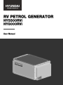
Hyundai power products HY8000RVi Owner's manual
- Category
- Power generators
- Type
- Owner's manual

1

2
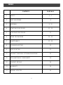
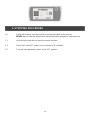
CONTENTS
PAGE NO.S
1
SAFETY
3 – 7
2
PART LOCATIONS
8
3
ASSEMBLY
9 - 12
4
STARTING PROCEDURE
12 - 13
5
STOPPING PROCEDURE
13
6
USING THE MACHINE
14 - 15
7
MAINTENANCE
15 - 19
8
TROUBLESHOOTING
20
9
SPECIFICATION
21
10
PRODUCT DISPOSAL & TROUBLESHOOTING
22
11
DECLARATION OF CONFORMITY
23
12
CONTACT DETAILS
24
13
WARRANTY
24
14
MANUAL UPDATES
24
INDEX

3
1.1 General Safety Notes.
1.2 The operator of the machine is responsible for, and has a duty of care in making sure
that the machine is operated safely and in accordance with the instructions in this
user manual. Keep the manual safe and pass it on if the machine is loaned or sold to
another user.
1.3 Please note the following safety points.
1.4 The machine should never be left it in a condition which would allow an untrained or
unauthorised person/s to operate this machine.
1.5 All due care and diligence should be taken by the operator for the safety of and with
regard to those around whilst using the machine.
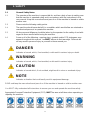
1.6 Some or all of the following - warning signs, symbols and/or PPE pictograms may
appear throughout this manual. You MUST adhere to their warnings. Failure to do
so may result in personal injury to yourself or those around you.
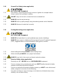
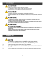
DANGER
Indicates a hazard, which, if not avoided, could result in serious injury or death.
WARNING
Indicates a hazard, which, if not avoided, could result in serious injury.
CAUTION
Indicates a hazard which, if not avoided, might result in minor or moderate injury.
NOTE
Indicates a situation that could easily result in equipment damage.
READ and keep the manual safe and pass it on if the machine is loaned or sold to another user.
You MUST fully understand all instructions to ensure you use and operate the machine safely.
Appropriate Personal Protective Equipment (PPE), MUST be worn at all times when operating or
repairing the machine.
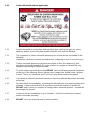
1. SAFETY

4
1.10 Carbon Monoxide (where applicable).
1.11 Carbon monoxide is a colourless and odourless gas. Inhaling this gas can cause
death as well as serious long term health problems such as brain damage.
1.12 The symptoms of carbon monoxide poisoning can include but are not limited to the
following;
Headaches, dizziness, nausea, breathlessness, collapsing or loss of consciousness.
1.13 Carbon monoxide poisoning symptoms are similar to flue, food poisoning, viral
infections and simply tiredness. It is quite common for people to mistake this very
dangerous poisoning for something else.
1.14 To avoid carbon monoxide poisoning DO NOT use Petrol/Diesel powered equipment
inside any of the following; Home, garage, tent, camper van, mobile home, caravan
or boat. This is not exhaustive and if you are in any doubt contact your dealer.
1.15 If you think you have or someone around you has been affected by carbon monoxide
poisoning;
1.16 Get them fresh air immediately, by leaving the affected area or by opening doors and
windows. If safe and practical to do so make sure that the machine is turned off.
DO NOT enter a room you suspect of having carbon monoxide present – instead call
the emergency services.
1.17 Contact a Doctor immediately or go to Hospital – let them know that you suspect
carbon monoxide poisoning.
1.18 DO NOT use in an enclosed area or moving vehicle.

5
1.20 General Fuel Safety (where applicable).
CAUTION
ALL FUELS ARE FLAMABLE
1.21 Fire Hazard – keep fuel away from all sources of ignition for example heaters.
Lamps, sparks from grinding or welding.
1.22 DO NOT carry out hot work on tanks that have contained fuel.
1.23 ALWAYS keep the work area tidy.
1.24 ALWAYS clean up spills promptly using absorbent granules and a lidded bin.
1.25 ALWAYS dispose of waste fuels correctly.
1.30 Fuelling/De-fuelling (where applicable).
CAUTION
ALL FUELS ARE FLAMABLE
1.31 ALWAYS fuel and defuel in a well-ventilated area outside of buildings.
1.32 ALWAYS wear correct, suitable and fit for purpose Personal Protective Equipment
(PPE), suggested items are but not limited to safety gloves, overalls.
1.33 When fuelling/de-fuelling ALWAYS avoid inhaling fumes.
1.34 When de-fuelling ALWAYS use a proper fuel retriever.
1.35 ALWAYS carry fuel in the correct and clearly marked container.
1.40 Electrical Safety (where applicable).
1.41 Electricity can kill – NEVER work on LIVE/ENERGISED equipment.
1.42 Prior to carrying out any maintenance work you MUST identify electrical isolation
methods and isolate all electrical supplies.
1.43 Prior to use and with all electrical supplies isolated, you MUST check all electrical
cables, plugs and connectors for the following;
1.44 Are intact and have no signs of damage, to include but not limited to bare wires,
chaffing, cuts and loose wiring.

6
1.45 If there are any signs of damage, the damaged item MUST be taken out of service
until the damage has been repaired by an electrically competent person.
1.46 All trailing cables should be routed so as not to cause any kind of trip hazard.
1.47 NEVER work on or near electricity with wet hands, wet clothing and wet gloves.
1.50 Batteries (where present).
1.51 Batteries present a risk if they become damaged by the possible leaking of
electrolyte. This electrolyte is an acid and can cause serious burn injuries. Care
should be taken when working on or near them. NOTE the electrolyte may be in
a liquid or gel form.
1.52 Should you come in to contact with electrolyte you should;
1.53 Remove all clothing contaminated with electrolyte. If you cannot remove then
saturate them in water.
1.54 Get medical assistance as soon as possible. You must advise the medical staff of
the type of acid.
1.55 Lead/acid battery = dilute sulphuric acid.
1.56 Nickel/cadmium = potassium hydroxide alkali electrolyte.
1.57 Use fresh running water to wash off excess electrolyte, continue this until medical
assistance arrives. Make sure that you do not was the electrolyte to another part of
your body or face.
1.58 If electrolyte comes in to contact with Eyes the electrolyte needs to be immediately
washed away with large amounts of water. Make sure that you do not wash the
electrolyte to another part of your face or body.
1.59 Gasses from charging batteries are highly flammable and great care should be taken
to charge in well ventilated areas.
1.59.1 There is an explosion risk if the battery terminals are short circuited, when
connecting/disconnecting ALWAYS exercise great care so that the terminals or
battery leads are NOT allowed to touch and cause a spark. ALWAYS use suitable
insulated tools.
1.60 Vibrations (where applicable).
1.61 Prolonged use of hand held (operated) machines will cause the user to feel the
effects of/from vibrations. These vibrations can lead to white finger (Raynaud’s
phenomenon) or carpal tunnel syndrome. This condition reduces the ability of the
hand to feel and regulate temperature, causing numbness and heat sensations and
may cause never damage and circulatory tissue death.
1.62 Not all factors that lead to white finger disease are known, but cold weather, smoking
and other diseases that affect blood vessels and blood circulation as well as large
and long-lasting impact of shocks are considered factors in the formation of white
finger. Note the following to reduce the risk of white finger and carpal tunnel
syndrome;
1.63 Wear gloves and keep your hands warm.
1.64 Take regular breaks.

7
1.65 All of the above precautions may help reduce the risk of white finger disease but not
rule out the carpal tunnel syndrome. Long-term and regular users are therefore
recommended to observe the condition of your hands and fingers. Seek medical
attention immediately if any of the above symptoms should occur.
1.70 Noise (where applicable).
1.71 The operating noise of the machine can damage your hearing. Wear hearing
protection such as earplugs or ear defenders to protect your hearing. Long-term
and regular users are advised to have hearing checked regularly. Be especially
vigilant and cautious when hearing ear protection because your ability to hear alarm
warnings will be reduced.
1.72 Noise emissions for this equipment is unavoidable. Carry out noisy work at approved
times and for certain periods. Limit the working time to a minimum. For your personal
protection and protection of people working nearby it is also advisable for them to
wear hearing protection.
1.73 See Certificate of Conformity section for Outdoor Noise declaration of
conformity.

8
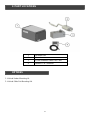
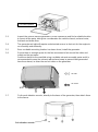
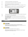
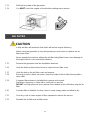
1
Generator Set
2
Exhaust
3
24 Litre Stainless Steel Fuel Tank
4
Remote LCM Controller
2. PART LOCATIONS
1. Vehicle Under Mounting Lit.
2. Vehicle Slide Out Mounting Kit.
2. PART LOCATIONS
OPTIONS

9
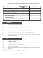
CAUTION
Always have assistance when lifting the generator.
The generator is heavy, lifting it could cause personal injury.
Avoid cutting on or near staples to prevent personal injury.
CAUTION
This device should only be installed by a qualified professional.
Improper installation can cause damage or serious injury to the generator, vehicle or
user.
WARNING
The exhaust will produce Carbon Monoxide, a colourless, odourless gas that if
inhaled can cause serious illness or death.
The exhaust gasses must exit away from any doors or window that may be opened
on the vehicle to avoid gasses entering the vehicle.
WARNING
ALL FUELS ARE FLAMMABLE
This product uses a separate fuel tank and must be installed in a safe location by a
professional.
Attention must be made to the location of the fuel tank and filler cap to ensure
installation complies with safety regulations.
NOTE
The generator is shipped without oil and MUST be filled before operation.
Recommended Oil: 1000ml of Semi-Synthetic SAE 15W40 Engine Oil.
3.0 Open the front panel and remove the oil filler cap/dipstick.
3.1 Slowly fill with 1000ml of semi-synthetic 15W40 engine oil, stop and check the level
as you fill.
3.2 Fill to the upper mark on the dipstick then securely replace the dipstick and panel.
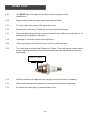
3. ASSEMBLY
GENERATOR

10
3.3 Inspect the vehicle that the generator is to be installed to and find a suitable location
to mount all the parts, taking into consideration the vehicle chassis, exhaust route,
fuel tank and brake lines.
3.4 The generator air inlet will require unobstructed access to fresh air for the engine to
run smoothly and efficiently.
3.5 Once a suitable mounting location has been found, install the generator.
3.6 Ensure there is enough space for the free movement of air around the inlets and
outlets on the generator.
Seal the exhaust to the manifold using a suitable exhaust assembly paste and it is
recommended to wrap the exhaust with exhaust wrap to prevent heat generated
from the exhaust, to enter the cool air inlets on the generator.
3.7 Fix the anti-vibration mounts, directly to the base of the generator, then attach them
to the frame.
Oil Filler/Dipstick
Air inlet
Air outlet

11
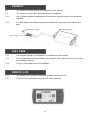
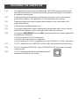
3.8 The exhaust must be fitted to the underside of the vehicle.
3.9 The exhaust comes with a flexi pipe for easy installation.
3.10 Use a suitable exhaust sealing paste to mount the exhaust flange to the generator
manifold.
3.11 It is advisable to use exhaust heat wrap between the exhaust flange and the flexi
pipe.
3.12 The fuel tank needs to be installed in a suitable and safe location
3.13 The fuel filler cap must be installed on the exterior of the vehicle and easy to access
for refuelling purposes.
3.14 Only use fuel grade hoses for installation.
3.15 The remote LCM controller should be installed for easy access.
3.16 Connect to the generator using the USB cable provided.
EXHAUST
E
x
ha
u
st
Fl
a
n
g
e
M
ou
n
t
i
n
g
H
a
n
g
a
r
Fl
e
x
i
P
i
p
e
FUEL TANK
REMOTE LCM

12
3.17 Use copper wires 16mm2or higher to connect to the vehicle battery.
3.18 Keep the distance from the battery to the generator as short as possible.
3.19 The generator on/off switch should be easy to access and near the remote LCM
controller.
IMPORTANT
DO NOT overload the generator. DO NOT overload individual output sockets.
If the current rating of any socket is exceeded, that generator will shut down AC
power and show as AC OFF on the remote LCM controller.
NOTE
Connect all electrical loads in the OFF position then turn ON for operation.
Turn all electrical loads OFF and disconnect from the generator before stopping the
generator.
Exceeding the generators wattage/current capacity could damage the generator
and/or the electrical devices connected to it.
DO NOT exceed the generators wattage/current capacity.
4.0 Turn the main generator power switch to the ON position.
4.1 Press the Power ON button on the remote LCM controller to start the generator.
4.2 The remote LCM controller should display AC OFF.
WIRING DIAGRAM
co
n
t
r
o
l
l
e
r
.
4. STARTING PROCEDURE

13
5.0 Switch off all loads and unplug then from the generator outlet sockets.
NEVER start or stop the engine with electrical devices plugged in and turned on.
5.1 Let the engine idle with no load for several minutes.
5.2 Press the Power OFF button on the remote LCM controller.
5.3 Turn the main generator switch to the OFF position.
5. STOPPING PROCEDURE

14
WARNING
The exhaust system heat and/or gasses could ignite combustible structures or
damage the fuel tank causing a fire, resulting in property damage, serious injury or
death.
Contact with the exhaust area could cause burns resulting in serious injury.
DO NOT touch hot parts and AVOID hot exhaust gasses.
You MUST allow the equipment to cool before touching.
IMPORTANT
DO NOT overload the generator. DO NOT overload individual output sockets.
If the current rating of any socket is exceeded, that generator will cut power to the
device and switch back to AC OFF mode.
NOTE
Connect all electrical loads in the OFF position then turn ON for operation.
Turn all electrical loads OFF and disconnect from the generator before stopping the
generator.
Exceeding the generators wattage/current capacity could damage the generator
and/or the electrical devices connected to it.
DO NOT exceed the generators wattage/current capacity.
6.0 If overloaded, the generator will cut the power supply and switch back to AC OFF
mode on the remote LCM controller.
6.1 Observe the following to prevent overloading of the unit;
Add up the total wattage of all electrical devices to be connected at one time.
This total should NOT be greater than the generators wattage capacity.
The rated wattage of lights can be taken from light bulbs.
The rated wattage of tools, appliances and motors can usually be found on a data
label or decal affixed to the devices.
If the appliance, tool or motor does not give wattage, multiply volts x ampere rating
to determine watts.
(volts x amps = watts)
6.2 Some electrical induction motors require about three times more power for starting
than for running.
This surge of power only lasts a few seconds when starting.
You MUST make sure you allow for high starting wattage when selecting electrical
devices to connect to the generator.
6. USING THE MACHINE

15
6.3 Calculate the watts needed to start the largest motor.
6.4 Add to that figure the running watts of all other connected loads.
6.5 Start the largest motor first and only one motor at a time.
6.6 With no electrical loads connected the remote LCM controller will display AC OFF to
save fuel.
6.7 Allow the generator to run under AC OFF for a few minutes to allow it to warm up.
6.8 After a few minutes press the AC ON button on the remote LCM controller.
6.9 Connect the electrical load to the generator socket with the electrical load turned off.
6.10 Once connected, turn on the electrical load.
6.11 Once running, the remote LCM controller will go into power save mode and the
screen will appear blank.
If you need to operate or check the generator status, press the Power ON button the
remote LCM controller.
DO NOT press the AC or OFF buttons in order to avoid turning the power off during
operation.
CAUTION
All maintenance work should be carried out by a trained professional.
Failure to follow service intervals may result in damage or poor performance of the
generator and may not be covered by warranty.
CAUTION
Always refuel in a well-ventilated area with the engine off.
Whilst carrying out maintenance you must wear appropriate Personal Protective
Equipment (PPE) when using this machine.
7. MAINTENANCE

16
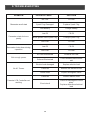
Suggested PPE: Sturdy footwear, work gloves, long trousers and hearing protection.
Maintenance
Every 100 Hours or 6
Months
Every 3 Years
Change Oil
X
Clean / Adjust Spark Plug
X
Clean / Adjust Valve Clearance
X
Change Air Filter Elements
X
Clean Fuel Tank & Filter
X
Check Exhaust Mounts
X
Replace Fuel Pipe
X
7.0 Cleaning the external of the generator.
7.1 Use a damp cloth to wipe exterior surfaces.
7.2 A soft bristle brush may be used to remove dust, dirt, oil etc.
7.3 A vacuum cleaner may be used to pick up loose dirt and debris.
7.4 Low pressure air (not to exceed 25 psi) may be used to blow away dirt.
7.5 Check cooling air slots and openings on the generator. These openings must be kept
clean and unobstructed.
7.6 Oil Type: Semi-Synthetic SAE 15W40 Engine Oil.
7.7 Oil capacity: 1000ml.
7.8 Ensure the generator is level.
7.9 Remove the front plate of the generator.
7.10 Unscrew the oil filler/dipstick.
7.11 Slowly fill with 1000ml of semi-synthetic 15W40 engine oil, stop and check the level
as you fill.
7.12Refit the oil filler cap and make sure the cap is tightened.
CLEANING
OIL

17
7.13 Refit the front plate of the generator.
7.14 You MUST check the engine oil level before starting every session.
CAUTION
A dirty air filter will restrict air flow which will reduce engine efficiency.
When using the generator in very dusty areas you must clean or replace the air
filter more often.
Never operate the machine without the air filter being fitted it can cause damage to
the engine which is not covered by warranty.
7.15 Remove the generator from the installation brackets.
7.16 Undo the bolts to the louvered cover to expose the air filter cover.
7.17 Undo the bolt on the air filter cover and remove.
7.18 Ensuring no dirt or debris can enter, clean the inside of the air filter housing with a
clean cloth.
7.19 If a paper filter element is installed then remove and inspect.
Replace if necessary or clean with a soft brush or vacuum.
DO NOT use high pressure air to remove dirt or debris as this will further clog the air
filter.
7.20 If a foam filter is installed, to clean, wash in warm soapy water and allow to dry.
7.21 Once dry, soak in clean engine oil then squeeze to remove the excess.
7.22 Reinstall the air filter and air filter cover.
AIR FILTER

18
7.23 You MUST allow the engine to cool down before carrying out any
maintenance.
7.24 Always replace with the same model spark plug as fitted.
7.25 To check spark plug, remove the generator cover.
7.26 Remove the spark plug HT lead cap and unscrew the spark plug.
7.27 Clean the spark plug electrode using a soft wire brush, making sure that there is no
damage to the insulator or electrode.
7.28 If damage is found then replace the spark plug.
7.29 If the spark plug is to be reused, then check the spark plug gap.
7.30 The spark plug gap should be 0.60mm to 0.70mm. Check the gap by using a feeler
gauge. Adjust as necessary by carefully bending the side electrode to achieve the
correct gap.
7.31 Refit the cleaned and adjusted spark plug by hand to avoid cross-threading.
7.32 After spark plug seats then tighten as necessary but avoid over-tightening.
7.33 Re-attach the spark plug cap and generator cover.
SPARK PLUG
0
.
6
m
m
t
o
0
.
7
m
m

19
7.34 The Requirement for Electrical installations BS 7971:2008 requires that the frame
and external electrically conductive part of this generator be properly connected to
an approved earth ground.
7.35 Proper grounding of the generator will help prevent electric shock in the event of
ground fault condition in the generator or in connected electrical devices.
7.36 Proper grounding also helps dissipate static electricity, which often builds up in
ungrounded devices.
7.37 Floating earth portable generator use.
7.38 This range of generators adopt a floating earth configuration which means that the
Neutral of the alternator is not connected to the Earth of the machine.
7.39 It is therefore IMPORTANT that you ONLY use the generator to supply equipment in
the following combinations.
7.40 One or more of CLASS II equipment.
7.41 Only ONE item of CLASS I equipment.
7.42 One or more of CLASS II equipment and only ONE item of CLASS I equipment.
7.43 CLASS I equipment has a GREEN/YELLOW earth wire connected inside the plug.
7.44 CLASS II equipment DOES NOT have a GREEN/YELLOW earth wire connected
inside the plug.
7.45 CLASS II equipment will have the following symbol
embossed or printed on the casing.
GROUNDING THE GENERATOR

20
PROBLEM
POSSIBLE CAUSE
SOLUTION
Generator won’t start
No Fuel
Fill Fuel
Spark Plug Damaged
Replace Spark Plug
Low Battery
Charge Battery
Generator starts but runs
poorly
Low Oil
Fill Oil
Weak ignition from Spark Plug
Change Spark Plug
Low Fuel
Fill Fuel
Generator shuts down during
operation
Low Oil
Fill Oil
Low Fuel
Fill Fuel
Not enough power
Air Flow Obstructed
Increase Air Flow
Exhaust Obstructed
Check exhaust has smooth
exit
No AC Power
Electric load damaged
Replace electric load
Overload
Reduce the electrical load
Loose wires
Inspect and tighten wires
Remote LCM Controller not
working
Overload
Reduce electric load
Short circuit
Check for damaged or loose
wires.
Replace defective electrical
load
8. TROUBLESHOOTING
Page is loading ...
Page is loading ...
Page is loading ...
Page is loading ...
Page is loading ...
Page is loading ...
-
 1
1
-
 2
2
-
 3
3
-
 4
4
-
 5
5
-
 6
6
-
 7
7
-
 8
8
-
 9
9
-
 10
10
-
 11
11
-
 12
12
-
 13
13
-
 14
14
-
 15
15
-
 16
16
-
 17
17
-
 18
18
-
 19
19
-
 20
20
-
 21
21
-
 22
22
-
 23
23
-
 24
24
-
 25
25
-
 26
26


Hyundai power products HY8000RVi Owner's manual
- Category
- Power generators
- Type
- Owner's manual
Ask a question and I''ll find the answer in the document
Finding information in a document is now easier with AI
Related papers
-
Hyundai power products DHY6000SELR DHY8000SELR DHY8000SELR-T Owner's manual
-
-
-
-
-
-
-
-
-
Other documents
-
Hyundai HY3500RVi User manual
-
-
-
Hyundai HY3000CI User manual
-
-
Hyundai HY7000LEK-2 User manual
-
-
-
-