Page is loading ...

UM10119
P89LPC938 User manual
Rev. 03 — 7 June 2005 User manual
Document information
Info Content
Keywords P89LPC938
Abstract Technical information for the P89LPC938 device.

© Koninklijke Philips Electronics N.V. 2005. All rights reserved.
User manual Rev. 03 — 7 June 2005 2 of 139
Philips Semiconductors
UM10119
P89LPC938 User manual
Contact information
For additional information, please visit: http://www.semiconductors.philips.com
For sales office addresses, please send an email to: sales.addresses@www.semiconductors.philips.com
Revision history
Rev Date Description
3 20050607
• Corrected typographical error in Table 50 “Capture compare control register (CCRx -
address Exh) bit description”. Corrected Table 107 “Data EEPROM control register
(DEECON address F1h) bit allocation” and Table 108 “Data EEPROM control register
(DEECON address F1h) bit description”.
• Revised Table 52 “Output compare pin behavior.” for OCMx1:0 =10.
2 20050304 Updated to 18 MHz spec
1 20050111 Initial version

© Koninklijke Philips Electronics N.V. 2005. All rights reserved.
User manual Rev. 03 — 7 June 2005 3 of 139
Philips Semiconductors
UM10119
P89LPC938 User manual
1. Introduction
The P89LPC938 is a single-chip microcontroller designed for applications demanding
high-integration, low cost solutions over a wide range of performance requirements. The
P89LPC938 is based on a high performance processor architecture that executes
instructions in two to four clocks, six times the rate of standard 80C51 devices. Many
system-level functions have been incorporated into the P89LPC938 in order to reduce
component count, board space, and system cost.
1.1 Pin configuration
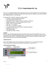
Fig 1. P89LPC938 TSSOP28 pin configuration.
P89LPC938FDH
002aab101
1
2
3
4
5
6
7
8
9
10
11
12
13
14
16
15
18
17
20
19
22
21
24
23
26
25
28
27
P2.0/ICB/AD07
P2.1/OCD/AD06
P0.0/CMP2/KBI0/AD05
P1.7/OCC/AD04
P1.6/OCB
P1.5/RST
V
SS
P3.1/XTAL1
P3.0/XTAL2/CLKOUT
P1.4/INT1
P1.3/INT0/SDA
P1.2/T0/SCL
P2.2/MOSI
P2.3/MISO
P2.7/ICA
P2.6/OCA
P0.1/CIN2B/KBI1/AD00
P0.2/CIN2A/KBI2/AD01
P0.3/CIN1B/KBI3/AD02
P0.4/CIN1A/KBI4/AD03
P0.5/CMPREF/KBI5
V
DD
P0.6/CMP1/KBI6
P0.7/T1/KBI7
P1.0/TXD
P1.1/RXD
P2.5/SPICLK
P2.4/SS

© Koninklijke Philips Electronics N.V. 2005. All rights reserved.
User manual Rev. 03 — 7 June 2005 4 of 139
Philips Semiconductors
UM10119
P89LPC938 User manual
Fig 2. P89LPC938 PLCC28 pin configuration.
Fig 3. P89LPC938 HVQFN28 pin configuration.
P89LPC938FA
002aab085
5
6
7
8
9
10
11
25
24
23
22
21
20
19
12
13
14
15
16
17
18
4
3
2
1
28
27
26
P1.6/OCB
P1.5/RST
V
SS
P3.1/XTAL1
P3.0/XTAL2/CLKOUT
P1.4/INT1
P1.3/INT0/SDA
P1.7/OCC/AD04
P0.0/CMP2/KBI0/AD05
P2.1/OCD/AD06
P2.0/ICB/AD07
P2.7/ICA
P2.6/OCA
P0.1/CIN2B/KBI1/AD00
P0.2/CIN2A/KBI2/AD01
P0.3/CIN1B/KBI3/AD02
P0.4/CIN1A/KBI4/AD03
P0.5/CMPREF/KBI5
V
DD
P0.6/CMP1/KBI6
P0.7/T1/KBI7
P1.2/T0/SCL
P2.2/MOSI
P2.3/MISO
P2.4/SS
P2.5/SPICLK
P1.1/RXD
P1.0/TXD
002aab073
P89LPC938FHN
Transparent top view
7 15
6 16
5 17
4 18
3
19
2 20
1 21
8
9
10
11
12
13
14
28
27
26
25
24
23
22
terminal 1
index area
P1.7/OCC/AD04
P2.7/ICA
P2.1/OCD/AD06
P2.0/ICB/AD07
P0.0/CMP2/KBI0/AD05
P2.6/OCA
P0.1/CIN2B/KBI1/AD00
P2.4/SS
P2.2/MOSI
P2.3/MISO
P1.2/T0/SCL
P2.5/SPICLK
P1.0/TXD
P1.1/RXD
P1.4/INT1
P1.3/INT0/SDA
P3.0/XTAL2/CLKOUT
P3.1/XTAL1
V
SS
P1.5/RST
P1.6/OCB
P0.6/CMP1/KBI6
P0.7/T1/KBI7
P0.5/CMPREF/KBI5
V
DD
P0.4/CIN1A/KBI4/AD03
P0.3/CIN1B/KBI3/AD02
P0.2/CIN2A/KBI2/AD01

© Koninklijke Philips Electronics N.V. 2005. All rights reserved.
User manual Rev. 03 — 7 June 2005 5 of 139
Philips Semiconductors
UM10119
P89LPC938 User manual
1.2 Pin description
Table 1: Pin description
Symbol Pin Type Description
TSSOP28,
PLCC28
HVQFN28
P0.0 to P0.7 I/O Port 0: Port 0 is an 8-bit I/O port with a user-configurable output type.
During reset Port 0 latches are configured in the input only mode with the
internal pull-up disabled. The operation of Port 0 pins as inputs and
outputs depends upon the port configuration selected. Each port pin is
configured independently. Refer to Section 5.1 “Port configurations” on
page 34 for details.
The Keypad Interrupt feature operates with Port 0 pins.
All pins have Schmitt triggered inputs.
Port 0 also provides various special functions as described below:
P0.0/CMP2/
KBI0/AD05
327I/OP0.0 — Port 0 bit 0.
O CMP2 — Comparator 2 output.
I KBI0 — Keyboard input 0.
I AD05 — ADC0 channel 5 analog input.
P0.1/CIN2B/
KBI1/AD00
26 22 I/O P0.1 — Port 0 bit 1.
I CIN2B — Comparator 2 positive input B.
I KBI1 — Keyboard input 1.
I AD00 — ADC0 channel 0 analog input.
P0.2/CIN2A/
KBI2/AD01
25 21 I/O P0.2 — Port 0 bit 2.
I CIN2A — Comparator 2 positive input A.
I KBI2 — Keyboard input 2.
I AD01 — ADC0 channel 1 analog input.
P0.3/CIN1B/
KBI3/AD02
24 20 I/O P0.3 — Port 0 bit 3.
I CIN1B — Comparator 1 positive input B.
I KBI3 — Keyboard input 3.
I AD02 — ADC0 channel 2 analog input.
P0.4/CIN1A/
KBI4/AD03
23 19 I/O P0.4 — Port 0 bit 4.
I CIN1A — Comparator 1 positive input A.
I KBI4 — Keyboard input 4.
I AD03 — ADC0 channel 3 analog input.
P0.5/CMPREF/
KBI5
22 18 I/O P0.5 — Port 0 bit 5.
I CMPREF — Comparator reference (negative) input.
I KBI5 — Keyboard input 5.

© Koninklijke Philips Electronics N.V. 2005. All rights reserved.
User manual Rev. 03 — 7 June 2005 6 of 139
Philips Semiconductors
UM10119
P89LPC938 User manual
P0.6/CMP1/
KBI6
20 16 I/O P0.6 — Port 0 bit 6.
O CMP1 — Comparator 1 output.
I KBI6 — Keyboard input 6.
P0.7/T1/KBI7 19 15 I/O P0.7 — Port 0 bit 7.
I/O T1 — Timer/counter 1 external count input or overflow output.
I KBI7 — Keyboard input 7.
P1.0 to P1.7 I/O, I
[1]
Port 1: Port 1 is an 8-bit I/O port with a user-configurable output type,
except for three pins as noted below. During reset Port 1 latches are
configured in the input only mode with the internal pull-up disabled. The
operation of the configurable Port 1 pins as inputs and outputs depends
upon the port configuration selected. Each of the configurable port pins
are programmed independently. Refer to Section 5.1 “
Port configurations”
on page 34 for details. P1.2 to P1.3 are open drain when used as outputs.
P1.5 is input only.
All pins have Schmitt triggered inputs.
Port 1 also provides various special functions as described below:
P1.0/TXD 18 14 I/O P1.0 — Port 1 bit 0.
O TXD — Transmitter output for the serial port.
P1.1/RXD 17 13 I/O P1.1 — Port 1 bit 1.
I RXD — Receiver input for the serial port.
P1.2/T0/SCL 12 8 I/O P1.2 — Port 1 bit 2 (open-drain when used as output).
I/O T0 — Timer/counter 0 external count input or overflow output (open-drain
when used as output).
I/O SCL — I
2
C serial clock input/output.
P1.3/INT0
/ SDA 11 7 I/O P1.3 — Port 1 bit 3 (open-drain when used as output).
I INT0
— External interrupt 0 input.
I/O SDA — I
2
C serial data input/output.
P1.4/INT1
10 6 I P1.4 — Port 1 bit 4.
I INT1
— External interrupt 1 input.
P1.5/RST
62IP1.5 — Port 1 bit 5 (input only).
I RST
— External Reset input during power-on or if selected via UCFG1.
When functioning as a reset input, a LOW on this pin resets the
microcontroller, causing I/O ports and peripherals to take on their default
states, and the processor begins execution at address 0. Also used
during a power-on sequence to force In-System Programming mode.
When using an oscillator frequency above 12 MHz, the reset input
function of P1.5 must be enabled. An external circuit is required to
hold the device in reset at power-up until V
DD
has reached its
specified level. When system power is removed V
DD
will fall below
the minimum specified operating voltage. When using an oscillator
frequency above 12 MHz, in some applications, an external
brownout detect circuit may be required to hold the device in reset
when V
DD
falls below the minimum specified operating voltage.
P1.6/OCB 5 1 I/O P1.6 — Port 1 bit 6.
O OCB — Output Compare B.
Table 1: Pin description
…continued
Symbol Pin Type Description
TSSOP28,
PLCC28
HVQFN28

© Koninklijke Philips Electronics N.V. 2005. All rights reserved.
User manual Rev. 03 — 7 June 2005 7 of 139
Philips Semiconductors
UM10119
P89LPC938 User manual
P1.7/OCC/
AD04
428I/OP1.7 — Port 1 bit 7.
O OCC — Output Compare C.
I AD04 — ADC0 channel 4 analog input.
P2.0 to P2.7 I/O Port 2: Port 2 is an 8-bit I/O port with a user-configurable output type.
During reset Port 2 latches are configured in the input only mode with the
internal pull-up disabled. The operation of Port 2 pins as inputs and
outputs depends upon the port configuration selected. Each port pin is
configured independently. Refer to Section 5.1 “
Port configurations” on
page 34 for details.
All pins have Schmitt triggered inputs.
Port 2 also provides various special functions as described below:
P2.0/ICB/ AD07 1 25 I/O P2.0 — Port 2 bit 0.
I ICB — Input Capture B.
I AD07 — ADC0 channel 7 analog input.
P2.1/OCD/
AD06
226I/OP2.1 — Port 2 bit 1.
O OCD — Output Compare D.
I AD06 — ADC0 channel 6 analog input.
P2.2/MOSI 13 9 I/O P2.2 — Port 2 bit 2.
I/O MOSI — SPI master out slave in. When configured as master, this pin is
output; when configured as slave, this pin is input.
P2.3/MISO 14 10 I/O P2.3 — Port 2 bit 3.
I/O MISO — When configured as master, this pin is input, when configured
as slave, this pin is output.
P2.4/SS
15 11 I/O P2.4 — Port 2 bit 4.
I SS
— SPI Slave select.
P2.5/SPICLK 16 12 I/O P2.5 — Port 2 bit 5.
I/O SPICLK — SPI clock. When configured as master, this pin is output;
when configured as slave, this pin is input.
P2.6/OCA 27 23 I/O P2.6 — Port 2 bit 6.
O OCA — Output Compare A.
P2.7/ICA 28 24 I/O P2.7 — Port 2 bit 7.
I ICA — Input Capture A.
P3.0 to P3.1 I/O Port 3: Port 3 is a 2-bit I/O port with a user-configurable output type.
During reset Port 3 latches are configured in the input only mode with the
internal pull-up disabled. The operation of Port 3 pins as inputs and
outputs depends upon the port configuration selected. Each port pin is
configured independently. Refer to Section 5.1 “
Port configurations” on
page 34 for details.
All pins have Schmitt triggered inputs.
Port 3 also provides various special functions as described below:
Table 1: Pin description
…continued
Symbol Pin Type Description
TSSOP28,
PLCC28
HVQFN28

© Koninklijke Philips Electronics N.V. 2005. All rights reserved.
User manual Rev. 03 — 7 June 2005 8 of 139
Philips Semiconductors
UM10119
P89LPC938 User manual
[1] Input/Output for P1.0 to P1.4, P1.6, P1.7. Input for P1.5.
P3.0/XTAL2/
CLKOUT
95I/OP3.0 — Port 3 bit 0.
O XTAL2 — Output from the oscillator amplifier (when a crystal oscillator
option is selected via the Flash configuration.
O CLKOUT — CPU clock divided by 2 when enabled via SFR bit (ENCLK
-TRIM.6). It can be used if the CPU clock is the internal RC oscillator,
watchdog oscillator or external clock input, except when XTAL1/XTAL2
are used to generate clock source for the RTC/system timer.
P3.1/XTAL1 8 4 I/O P3.1 — Port 3 bit 1.
I XTAL1 — Input to the oscillator circuit and internal clock generator
circuits (when selected via the Flash configuration). It can be a port pin if
internal RC oscillator or watchdog oscillator is used as the CPU clock
source, and if XTAL1/XTAL2 are not used to generate the clock for the
RTC/system timer.
V
SS
73IGround: 0 V reference.
V
DD
21 17 I Power Supply: This is the power supply voltage for normal operation as
well as Idle and Power-Down modes.
Table 1: Pin description …continued
Symbol Pin Type Description
TSSOP28,
PLCC28
HVQFN28

© Koninklijke Philips Electronics N.V. 2005. All rights reserved.
User manual Rev. 03 — 7 June 2005 9 of 139
Philips Semiconductors
UM10119
P89LPC938 User manual
Fig 4. P89LPC938 block diagram.
ACCELERATED 2-CLOCK 80C51 CPU
8 kB
CODE FLASH
256-BYTE
DATA RAM
PORT 2
CONFIGURABLE I/Os
PORT 1
CONFIGURABLE I/Os
PORT 0
CONFIGURABLE I/Os
KEYPAD
INTERRUPT
PROGRAMMABLE
OSCILLATOR DIVIDER
CPU
clock
CONFIGURABLE
OSCILLATOR
ON-CHIP
RC
OSCILLATOR
internal
bus
CRYSTAL
OR
RESONATOR
POWER MONITOR
(POWER-ON RESET,
BROWNOUT RESET)
002aab106
UART
ANALOG
COMPARATORS
512-BYTE
AUXILIARY RAM
I
2
C-BUS
512-BYTE
DATA EEPROM
PORT 3
CONFIGURABLE I/Os
CCU (CAPTURE/
COMPARE UNIT)
P89LPC938
WATCHDOG TIMER
AND OSCILLATOR
TIMER 0
TIMER 1
REAL-TIME CLOCK/
SYSTEM TIMER
SPI
ADC0
P3[1:0]
P2[7:0]
P1[7:0]
P0[7:0]
X2
X1
TXD
RXD
SCL
SDA
T0
T1
CMP2
CIN2B
CIN2A
CMP1
CIN1A
CIN1B
OCA
OCB
OCC
OCD
ICA
AD00
AD01
AD02
AD03
AD04
AD05
AD06
AD07
ICB
SPICLK
MOSI
MISO
SS

© Koninklijke Philips Electronics N.V. 2005. All rights reserved.
User manual Rev. 03 — 7 June 2005 10 of 139
Philips Semiconductors
UM10119
P89LPC938 User manual
1.3 Special function registers
Remark: Special Function Registers (SFRs) accesses are restricted in the following ways:
• User must not attempt to access any SFR locations not defined.
• Accesses to any defined SFR locations must be strictly for the functions for the SFRs.
• SFR bits labeled ‘-’, ‘0’ or ‘1’ can only be written and read as follows:
– ‘-’ Unless otherwise specified, must be written with ‘0’, but can return any value
when read (even if it was written with ‘0’). It is a reserved bit and may be used in
future derivatives.
– ‘0’ must be written with ‘0’, and will return a ‘0’ when read.
– ‘1’ must be written with ‘1’, and will return a ‘1’ when read.

xxxxxxxxxxxxxxxxxxxxx xxxxxxxxxxxxxxxxxxxxxxxxxx xxxxxxx x x x xxxxxxxxxxxxxxxxxxxxxxxxxxxxxx xxxxxxxxxxxxxxxxxxx xx xx xxxxx
xxxxxxxxxxxxxxxxxxxxxxxxxxx xxxxxxxxxxxxxxxxxxx xxxxxx xxxxxxxxxxxxxxxxxxxxxxxxxxxxxxxxxxx xxxxxxxxxxxx x x
xxxxxxxxxxxxxxxxxxxxx xxxxxxxxxxxxxxxxxxxxxxxxxxxxxx xxxxx xxxxxxxxxxxxxxxxxxxxxxxxxxxxxxxxxxxxxxxxxxxxxxxxxx xxxxxxxx
xxxxxxxxxxxxxxxxxxxxxxxxx xxxxxxxxxxxxxxxxxxxx xxx
© Koninklijke Philips Electronics N.V. 2005. All rights reserved.
User manual Rev. 03 — 7 June 2005 11 of 139
Philips Semiconductors
UM10119
P89LPC938 User manual
Table 2: P89LPC938 Special function registers
* indicates SFRs that are bit addressable.
Name Description SFR
addr.
Bit functions and addresses Reset value
MSB LSB Hex Binary
Bit addressE7E6E5E4E3E2E1E0
ACC* Accumulator E0H 00 0000 0000
AD0CON ADC0 control register 97H ENBI0 ENADCI
0
TMM0 EDGE0 ADCI0 ENADC0 ADCS01 ADCS00 00 0000 0000
AD0INS ADC0 input select A3H ADI07 ADI06 ADI05 ADI04 ADI03 ADI02 ADI01 ADI00 00 0000 0000
AD0MOD
A
ADC0 mode registerAC0HBNDI0BURST0SCC0SCAN0----0000000000
AD0MOD
B
ADC0 mode registerBA1HCLK2CLK1CLK0-----00000x0000
AUXR1 Auxiliary function register A2H CLKLP EBRR ENT1 ENT0 SRST 0 - DPS 00 0000 00x0
Bit addressF7F6F5F4F3F2F1F0
B* B register F0H 00 0000 0000
BRGR0
[2]
Baud rate generator rate
low
BEH 00 0000 0000
BRGR1
[2]
Baud rate generator rate
high
BFH 00 0000 0000
BRGCONBaud rate generator controlBDH------SBRGSBRGEN00
[2]
xxxx xx00
CCCRA Capture compare A control
register
EAH ICECA2 ICECA1 ICECA0 ICESA ICNFA FCOA OCMA1 OCMA0 00 0000 0000
CCCRB Capture compare B control
register
EBH ICECB2 ICECB1 ICECB0 ICESB ICNFB FCOB OCMB1 OCMB0 00 0000 0000
CCCRC Capture compare C control
register
ECH-----FCOCOCMC1OCMC000xxxxx000
CCCRD Capture compare D control
register
EDH-----FCODOCMD1OCMD000xxxxx000
CMP1 Comparator 1 control
register
ACH - - CE1 CP1 CN1 OE1 CO1 CMF1 00
[1]
xx00 0000
CMP2 Comparator 2 control
register
ADH - - CE2 CP2 CN2 OE2 CO2 CMF2 00
[1]
xx00 0000
DEECON Data EEPROM control
register
F1H EEIF HVERR ECTL1 ECTL0 - - - EADR8 0E 0000 1110

xxxxxxxxxxxxxxxxxxxxx xxxxxxxxxxxxxxxxxxxxxxxxxx xxxxxxx x x x xxxxxxxxxxxxxxxxxxxxxxxxxxxxxx xxxxxxxxxxxxxxxxxxx xx xx xxxxx
xxxxxxxxxxxxxxxxxxxxxxxxxxx xxxxxxxxxxxxxxxxxxx xxxxxx xxxxxxxxxxxxxxxxxxxxxxxxxxxxxxxxxxx xxxxxxxxxxxx x x
xxxxxxxxxxxxxxxxxxxxx xxxxxxxxxxxxxxxxxxxxxxxxxxxxxx xxxxx xxxxxxxxxxxxxxxxxxxxxxxxxxxxxxxxxxxxxxxxxxxxxxxxxx xxxxxxxx
xxxxxxxxxxxxxxxxxxxxxxxxx xxxxxxxxxxxxxxxxxxxx xxx
© Koninklijke Philips Electronics N.V. 2005. All rights reserved.
User manual Rev. 03 — 7 June 2005 12 of 139
Philips Semiconductors
UM10119
P89LPC938 User manual
DEEDAT Data EEPROM data
register
F2H 00 0000 0000
DEEADR Data EEPROM address
register
F3H 00 0000 0000
DIVM CPU clock divide-by-M
control
95H 00 0000 0000
DPTR Data pointer (2 bytes)
DPH Data pointer high 83H 00 0000 0000
DPL Data pointer low 82H 00 0000 0000
FMADRH Program Flash address
high
E7H 00 0000 0000
FMADRL Program Flash address low E6H 00 0000 0000
FMCON Program Flash control
(Read)
E4H BUSY - - - HVA HVE SV OI 70 0111 0000
Program Flash control
(Write)
E4H FMCMD.
7
FMCMD.
6
FMCMD.
5
FMCMD.
4
FMCMD.
3
FMCMD.
2
FMCMD.
1
FMCMD.
0
FMDATA Program Flash data E5H 00 0000 0000
I2ADR I
2
C slave address register DBH I2ADR.6 I2ADR.5 I2ADR.4 I2ADR.3 I2ADR.2 I2ADR.1 I2ADR.0 GC 00 0000 0000
Bit address DF DE DD DC DB DA D9 D8
I2CON* I
2
C control register D8H - I2EN STA STO SI AA - CRSEL 00 x000 00x0
I2DAT I
2
C data register DAH
I2SCLH Serial clock generator/SCL
duty cycle register high
DDH 00 0000 0000
I2SCLL Serial clock generator/SCL
duty cycle register low
DCH 00 0000 0000
I2STAT I
2
C status register D9H STA.4 STA.3 STA.2 STA.1 STA.0 0 0 0 F8 1111 1000
ICRAH Input capture A register
high
ABH 00 0000 0000
ICRAL Input capture A register low AAH 00 0000 0000
ICRBH Input capture B register
high
AFH 00 0000 0000
ICRBL Input capture B register low AEH 00 0000 0000
Table 2: P89LPC938 Special function registers
…continued
* indicates SFRs that are bit addressable.
Name Description SFR
addr.
Bit functions and addresses Reset value
MSB LSB Hex Binary

xxxxxxxxxxxxxxxxxxxxx xxxxxxxxxxxxxxxxxxxxxxxxxx xxxxxxx x x x xxxxxxxxxxxxxxxxxxxxxxxxxxxxxx xxxxxxxxxxxxxxxxxxx xx xx xxxxx
xxxxxxxxxxxxxxxxxxxxxxxxxxx xxxxxxxxxxxxxxxxxxx xxxxxx xxxxxxxxxxxxxxxxxxxxxxxxxxxxxxxxxxx xxxxxxxxxxxx x x
xxxxxxxxxxxxxxxxxxxxx xxxxxxxxxxxxxxxxxxxxxxxxxxxxxx xxxxx xxxxxxxxxxxxxxxxxxxxxxxxxxxxxxxxxxxxxxxxxxxxxxxxxx xxxxxxxx
xxxxxxxxxxxxxxxxxxxxxxxxx xxxxxxxxxxxxxxxxxxxx xxx
© Koninklijke Philips Electronics N.V. 2005. All rights reserved.
User manual Rev. 03 — 7 June 2005 13 of 139
Philips Semiconductors
UM10119
P89LPC938 User manual
Bit address AF AE AD AC AB AA A9 A8
IEN0* Interrupt enable 0 A8H EA EWDRT EBO ES/ESR ET1 EX1 ET0 EX0 00 0000 0000
Bit address EF EE ED EC EB EA E9 E8
IEN1* Interrupt enable 1 E8H EIEE EST - ECCU ESPI EC EKBI EI2C 00
[1]
00x0 0000
IEN2Interrupt enable 2 D5H------EADC-00
[1]
00x0 0000
Bit address BF BE BD BC BB BA B9 B8
IP0* Interrupt priority 0 B8H - PWDRT PBO PS/PSR PT1 PX1 PT0 PX0 00
[1]
x000 0000
IP0H Interrupt priority 0 high B7H - PWDRT
H
PBOH PSH/
PSRH
PT1H PX1H PT0H PX0H 00
[1]
x000 0000
Bit address FF FE FD FC FB FA F9 F8
IP1* Interrupt priority 1 F8H PADEE PST - PCCU PSPI PC PKBI PI2C 00
[1]
00x0 0000
IP1H Interrupt priority 1 high F7H PADEEH PSTH - PCCUH PSPIH PCH PKBIH PI2CH 00
[1]
00x0 0000
IP2Interrupt priority 2 D6H------PADC-00
[1]
00x0 0000
IP2HInterrupt priority 2 highD7H------PADCH-00
[1]
00x0 0000
KBCONKeypad control register94H------PATN
_SEL
KBIF 00
[1]
xxxx xx00
KBMASK Keypad interrupt mask
register
86H 00 0000 0000
KBPATN Keypad pattern register 93H FF 1111 1111
OCRAH Output compare A register
high
EFH 00 0000 0000
OCRAL Output compare A register
low
EEH 00 0000 0000
OCRBH Output compare B register
high
FBH 00 0000 0000
OCRBL Output compare B register
low
FAH 00 0000 0000
OCRCH Output compare C register
high
FDH 00 0000 0000
OCRCL Output compare C register
low
FCH 00 0000 0000
Table 2: P89LPC938 Special function registers
…continued
* indicates SFRs that are bit addressable.
Name Description SFR
addr.
Bit functions and addresses Reset value
MSB LSB Hex Binary

xxxxxxxxxxxxxxxxxxxxx xxxxxxxxxxxxxxxxxxxxxxxxxx xxxxxxx x x x xxxxxxxxxxxxxxxxxxxxxxxxxxxxxx xxxxxxxxxxxxxxxxxxx xx xx xxxxx
xxxxxxxxxxxxxxxxxxxxxxxxxxx xxxxxxxxxxxxxxxxxxx xxxxxx xxxxxxxxxxxxxxxxxxxxxxxxxxxxxxxxxxx xxxxxxxxxxxx x x
xxxxxxxxxxxxxxxxxxxxx xxxxxxxxxxxxxxxxxxxxxxxxxxxxxx xxxxx xxxxxxxxxxxxxxxxxxxxxxxxxxxxxxxxxxxxxxxxxxxxxxxxxx xxxxxxxx
xxxxxxxxxxxxxxxxxxxxxxxxx xxxxxxxxxxxxxxxxxxxx xxx
© Koninklijke Philips Electronics N.V. 2005. All rights reserved.
User manual Rev. 03 — 7 June 2005 14 of 139
Philips Semiconductors
UM10119
P89LPC938 User manual
OCRDH Output compare D register
high
FFH 00 0000 0000
OCRDL Output compare D register
low
FEH 00 0000 0000
Bit address8786858483828180
P0* Port 0 80H T1/KB7 CMP1
/KB6
CMPREF
/KB5
CIN1A
/KB4
CIN1B
/KB3
CIN2A
/KB2
CIN2B
/KB1
CMP2
/KB0
[1]
Bit address9796959493929190
P1* Port 1 90H OCC OCB RST
INT1 INT0/
SDA
T0/SCL RXD TXD
[1]
Bit address9796959493929190
P2* Port 2 A0H ICA OCA SPICLK SS
MISO MOSI OCD ICB
[1]
Bit addressB7B6B5B4B3B2B1B0
P3*Port3 B0H------XTAL1XTAL2
[1]
P0M1 Port 0 output mode 1 84H (P0M1.7) (P0M1.6) (P0M1.5) (P0M1.4) (P0M1.3) (P0M1.2) (P0M1.1) (P0M1.0) FF
[1]
1111 1111
P0M2 Port 0 output mode 2 85H (P0M2.7) (P0M2.6) (P0M2.5) (P0M2.4) (P0M2.3) (P0M2.2) (P0M2.1) (P0M2.0) 00
[1]
0000 0000
P1M1 Port 1 output mode 1 91H (P1M1.7) (P1M1.6) - (P1M1.4) (P1M1.3) (P1M1.2) (P1M1.1) (P1M1.0) D3
[1]
11x1 xx11
P1M2 Port 1 output mode 2 92H (P1M2.7) (P1M2.6) - (P1M2.4) (P1M2.3) (P1M2.2) (P1M2.1) (P1M2.0) 00
[1]
00x0 xx00
P2M1 Port 2 output mode 1 A4H (P2M1.7) (P2M1.6) (P2M1.5) (P2M1.4) (P2M1.3) (P2M1.2) (P2M1.1) (P2M1.0) FF
[1]
1111 1111
P2M2 Port 2 output mode 2 A5H (P2M2.7) (P2M2.6) (P2M2.5) (P2M2.4) (P2M2.3) (P2M2.2) (P2M2.1) (P2M2.0) 00
[1]
0000 0000
P3M1Port3 output mode1B1H------(P3M1.1)(P3M1.0)03
[1]
xxxx xx11
P3M2Port3 output mode2B2H------(P3M2.1)(P3M2.0)00
[1]
xxxx xx00
PCON Power control register 87H SMOD1 SMOD0 BOPD BOI GF1 GF0 PMOD1 PMOD0 00 0000 0000
PCONA Power control register A B5H RTCPD DEEPD VCPD ADPD I2PD SPPD SPD CCUPD 00
[1]
0000 0000
Bit addressD7D6D5D4D3D2D1D0
PSW* Program status word D0H CY AC F0 RS1 RS0 OV F1 P 00 0000 0000
PT0AD Port 0 digital input disable F6H - - PT0AD.5 PT0AD.4 PT0AD.3 PT0AD.2 PT0AD.1 - 00 xx00 000x
RSTSRC Reset source register DFH - - BOF POF R_BK R_WD R_SF R_EX
[3]
RTCCON RTC control D1H RTCF RTCS1 RTCS0 - - - ERTC RTCEN 60
[1][6]
011x xx00
Table 2: P89LPC938 Special function registers
…continued
* indicates SFRs that are bit addressable.
Name Description SFR
addr.
Bit functions and addresses Reset value
MSB LSB Hex Binary

xxxxxxxxxxxxxxxxxxxxx xxxxxxxxxxxxxxxxxxxxxxxxxx xxxxxxx x x x xxxxxxxxxxxxxxxxxxxxxxxxxxxxxx xxxxxxxxxxxxxxxxxxx xx xx xxxxx
xxxxxxxxxxxxxxxxxxxxxxxxxxx xxxxxxxxxxxxxxxxxxx xxxxxx xxxxxxxxxxxxxxxxxxxxxxxxxxxxxxxxxxx xxxxxxxxxxxx x x
xxxxxxxxxxxxxxxxxxxxx xxxxxxxxxxxxxxxxxxxxxxxxxxxxxx xxxxx xxxxxxxxxxxxxxxxxxxxxxxxxxxxxxxxxxxxxxxxxxxxxxxxxx xxxxxxxx
xxxxxxxxxxxxxxxxxxxxxxxxx xxxxxxxxxxxxxxxxxxxx xxx
© Koninklijke Philips Electronics N.V. 2005. All rights reserved.
User manual Rev. 03 — 7 June 2005 15 of 139
Philips Semiconductors
UM10119
P89LPC938 User manual
RTCH RTC register high D2H 00
[6]
0000 0000
RTCL RTC register low D3H 00
[6]
0000 0000
SADDR Serial port address register A9H 00 0000 0000
SADEN Serial port address enable B9H 00 0000 0000
SBUF Serial Port data buffer
register
99H xx xxxx xxxx
Bit address 9F 9E 9D 9C 9B 9A 99 98
SCON* Serial port control 98H SM0/FE SM1 SM2 REN TB8 RB8 TI RI 00 0000 0000
SSTAT Serial port extended status
register
BAH DBMOD INTLO CIDIS DBISEL FE BR OE STINT 00 0000 0000
SP Stack pointer 81H 07 0000 0111
SPCTL SPI control register E2H SSIG SPEN DORD MSTR CPOL CPHA SPR1 SPR0 04 0000 0100
SPSTAT SPI status register E1H SPIF WCOL ------0000xxxxxx
SPDAT SPI data register E3H 00 0000 0000
TAMOD Timer 0 and 1 auxiliary
mode
8FH - - - T1M2 - - - T0M2 00 xxx0 xxx0
Bit address 8F 8E 8D 8C 8B 8A 89 88
TCON* Timer 0 and 1 control 88H TF1 TR1 TF0 TR0 IE1 IT1 IE0 IT0 00 0000 0000
TCR20* CCU control register 0 C8H PLEEN HLTRN HLTEN ALTCD ALTAB TDIR2 TMOD21 TMOD20 00 0000 0000
TCR21 CCU control register 1 F9H TCOU2 - - - PLLDV.3 PLLDV.2 PLLDV.1 PLLDV.0 00 0xxx 0000
TH0 Timer 0 high 8CH 00 0000 0000
TH1 Timer 1 high 8DH 00 0000 0000
TH2 CCU timer high CDH 00 0000 0000
TICR2 CCU interrupt control
register
C9H TOIE2 TOCIE2D TOCIE2C TOCIE2B TOCIE2A - TICIE2B TICIE2A 00 0000 0x00
TIFR2 CCU interrupt flag register E9H TOIF2 TOCF2D TOCF2C TOCF2B TOCF2A - TICF2B TICF2A 00 0000 0x00
TISE2 CCU interrupt status
encode register
DEH-----ENCINT.
2
ENCINT.
1
ENCINT.
0
00 xxxx x000
TL0 Timer 0 low 8AH 00 0000 0000
TL1 Timer 1 low 8BH 00 0000 0000
Table 2: P89LPC938 Special function registers
…continued
* indicates SFRs that are bit addressable.
Name Description SFR
addr.
Bit functions and addresses Reset value
MSB LSB Hex Binary

xxxxxxxxxxxxxxxxxxxxx xxxxxxxxxxxxxxxxxxxxxxxxxx xxxxxxx x x x xxxxxxxxxxxxxxxxxxxxxxxxxxxxxx xxxxxxxxxxxxxxxxxxx xx xx xxxxx
xxxxxxxxxxxxxxxxxxxxxxxxxxx xxxxxxxxxxxxxxxxxxx xxxxxx xxxxxxxxxxxxxxxxxxxxxxxxxxxxxxxxxxx xxxxxxxxxxxx x x
xxxxxxxxxxxxxxxxxxxxx xxxxxxxxxxxxxxxxxxxxxxxxxxxxxx xxxxx xxxxxxxxxxxxxxxxxxxxxxxxxxxxxxxxxxxxxxxxxxxxxxxxxx xxxxxxxx
xxxxxxxxxxxxxxxxxxxxxxxxx xxxxxxxxxxxxxxxxxxxx xxx
© Koninklijke Philips Electronics N.V. 2005. All rights reserved.
User manual Rev. 03 — 7 June 2005 16 of 139
Philips Semiconductors
UM10119
P89LPC938 User manual
[1] All ports are in input only (high-impedance) state after power-up.
[2] BRGR1 and BRGR0 must only be written if BRGEN in BRGCON SFR is logic 0. If any are written while BRGEN = 1, the result is unpredictable.
[3] The RSTSRC register reflects the cause of the UM10119 reset. Upon a power-up reset, all reset source flags are cleared except POF and BOF; the power-on reset value is
xx11 0000.
[4] After reset, the value is 1110 01x1, i.e., PRE2 to PRE0 are all logic 1, WDRUN = 1 and WDCLK = 1. WDTOF bit is logic 1 after watchdog reset and is logic 0 after power-on reset.
Other resets will not affect WDTOF.
[5] On power-on reset, the TRIM SFR is initialized with a factory preprogrammed value. Other resets will not cause initialization of the TRIM register.
[6] The only reset source that affects these SFRs is power-on reset.
TL2 CCU timer low CCH 00 0000 0000
TMOD Timer 0 and 1 mode 89H T1GATE T1C/T T1M1 T1M0 T0GATE T0C/T T0M1 T0M0 00 0000 0000
TOR2H CCU reload register high CFH 00 0000 0000
TOR2L CCU reload register low CEH 00 0000 0000
TPCR2H Prescaler control register
high
CBH------TPCR2H.
1
TPCR2H.
0
00 xxxx xx00
TPCR2L Prescaler control register
low
CAH TPCR2L.
7
TPCR2L.
6
TPCR2L.
5
TPCR2L.
4
TPCR2L.
3
TPCR2L.
2
TPCR2L.
1
TPCR2L.
0
00 0000 0000
TRIM Internal oscillator trim
register
96H RCCLK ENCLK TRIM.5 TRIM.4 TRIM.3 TRIM.2 TRIM.1 TRIM.0
[5]
[6]
WDCON Watchdog control register A7H PRE2 PRE1 PRE0 - - WDRUN WDTOF WDCLK
[4]
[6]
WDL Watchdog load C1H FF 1111 1111
WFEED1 Watchdog feed 1 C2H
WFEED2 Watchdog feed 2 C3H
Table 2: P89LPC938 Special function registers
…continued
* indicates SFRs that are bit addressable.
Name Description SFR
addr.
Bit functions and addresses Reset value
MSB LSB Hex Binary

xxxxxxxxxxxxxxxxxxxxx xxxxxxxxxxxxxxxxxxxxxxxxxx xxxxxxx x x x xxxxxxxxxxxxxxxxxxxxxxxxxxxxxx xxxxxxxxxxxxxxxxxxx xx xx xxxxx
xxxxxxxxxxxxxxxxxxxxxxxxxxx xxxxxxxxxxxxxxxxxxx xxxxxx xxxxxxxxxxxxxxxxxxxxxxxxxxxxxxxxxxx xxxxxxxxxxxx x x
xxxxxxxxxxxxxxxxxxxxx xxxxxxxxxxxxxxxxxxxxxxxxxxxxxx xxxxx xxxxxxxxxxxxxxxxxxxxxxxxxxxxxxxxxxxxxxxxxxxxxxxxxx xxxxxxxx
xxxxxxxxxxxxxxxxxxxxxxxxx xxxxxxxxxxxxxxxxxxxx xxx
© Koninklijke Philips Electronics N.V. 2005. All rights reserved.
User manual Rev. 03 — 7 June 2005 17 of 139
Philips Semiconductors
UM10119
P89LPC938 User manual
[1] Extended SFRs are logically in external data memory space (XDATA) and are accessed using the MOVX A,@DPTR and MOVX @DPTR,A instructions.
Table 3: P89LPC938 extended special function registers
[1]
Name Description SFR addr. Bit functions and addresses Reset value
MSB LSB Hex Binary
ADC0HBND ADC0 high _boundary register, left
(MSB)
FFEFh FF 1111 1111
ADC0LBND ADC0 low_boundary register (MSB) FFEEh 00 0000 0000
AD0DAT0R ADC0 data register 0, right (LSB) FFFEh AD0DAT0[7:0] 00 0000 0000
AD0DAT0L ADC0 data register 0, left (MSB) FFFFh AD0DAT0[9:2] 00 0000 0000
AD0DAT1R ADC0 data register 1, right (LSB) FFFCh AD0DAT1[7:0] 00 0000 0000
AD0DAT1L ADC0 data register 1, left (MSB) FFFDh AD0DAT1[9:2] 00 0000 0000
AD0DAT2R ADC0 data register 2, right (LSB) FFFAh AD0DAT2[7:0] 00 0000 0000
AD0DAT2L ADC0 data register 2, left (MSB) FFFBh AD0DAT2[9:2] 00 0000 0000
AD0DAT3R ADC0 data register 3, right (LSB) FFF8h AD0DAT3[7:0] 00 0000 0000
AD0DAT3L ADC0 data register 3, left (MSB) FFF9h AD0DAT3[9:2] 00 0000 0000
AD0DAT4R ADC0 data register 4, right (LSB) FFF6h AD0DAT4[7:0] 00 0000 0000
AD0DAT4L ADC0 data register 4, left (MSB) FFF7h AD0DAT4[9:2] 00 0000 0000
AD0DAT5R ADC0 data register 5, right (LSB) FFF4h AD0DAT5[7:0] 00 0000 0000
AD0DAT5L ADC0 data register 5, left (MSB) FFF5h AD0DAT5[9:2] 00 0000 0000
AD0DAT6R ADC0 data register 6, right (LSB) FFF2h AD0DAT6[7:0] 00 0000 0000
AD0DAT6L ADC0 data register 6, left (MSB) FFF3h AD0DAT6[9:2] 00 0000 0000
AD0DAT7R ADC0 data register 7, right (LSB) FFF0h AD0DAT7[7:0] 00 0000 0000
AD0DAT7L ADC0 data register 7, left (MSB) FFF1h AD0DAT7[9:2] 00 0000 0000
BNDSTA0 ADC0 boundary status register FFEDh BST07 BST06 BST05 BST04 BST03 BST02 BST01 BST00 00 0000 0000

© Koninklijke Philips Electronics N.V. 2005. All rights reserved.
User manual Rev. 03 — 7 June 2005 18 of 139
Philips Semiconductors
UM10119
P89LPC938 User manual
1.4 Memory organization
The various P89LPC938 memory spaces are as follows:
DATA — 128 bytes of internal data memory space (00h:7Fh) accessed via direct or
indirect addressing, using instruction other than MOVX and MOVC. All or part of the Stack
may be in this area.
IDATA — Indirect Data. 256 bytes of internal data memory space (00h:FFh) accessed via
indirect addressing using instructions other than MOVX and MOVC. All or part of the
Stack may be in this area. This area includes the DATA area and the 128 bytes
immediately above it.
SFR — Special Function Registers. Selected CPU registers and peripheral control and
status registers, accessible only via direct addressing.
CODE — 64 kB of Code memory space, accessed as part of program execution and via
the MOVC instruction. The P89LPC938 has 8 kB of on-chip Code memory.
Fig 5. P89LPC938 memory map.
002aaa948
0000h
03FFh
0400h
07FFh
0800h
0BFFh
0C00h
0FFFh
SECTOR 0
SECTOR 1
SECTOR 2
SECTOR 3
1000h
13FFh
1400h
17FFh
1800h
1BFFh
1C00h
1E00h
1FFFh
SECTOR 4
SECTOR 5
SECTOR 6
FFEFh
FF00h
IAP entry-
points
SECTOR 7
ISP CODE
(512B)*
SPECIAL FUNCTION
REGISTERS
(DIRECTLY ADDRESSABLE)
128 BYTES ON-CHIP
DATA MEMORY (STACK,
DIRECT AND INDIR. ADDR.)
4 REG. BANKS R[7:0]
data memory
(DATA, IDATA)
DATA
128 BYTES ON-CHIP
DATA MEMORY (STACK
AND INDIR. ADDR.)
IDATA (incl. DATA)
FFEFh
FF1Fh
FF00h
entry points for:
-51 ASM. code
-C code
IDATA routines
1FFFh
1E00h
entry points for:
-UART (auto-baud)
-I2C, SPI, etc.*
Flexible choices:
-as supplied (UART)
-Philips libraries*
-user-defined
ISP serial loader
entry
points
Read-protected
IAP calls only
Table 4: Data RAM arrangement
Type Data RAM Size (bytes)
DATA Directly and indirectly addressable memory 128
IDATA Indirectly addressable memory 256

© Koninklijke Philips Electronics N.V. 2005. All rights reserved.
User manual Rev. 03 — 7 June 2005 19 of 139
Philips Semiconductors
UM10119
P89LPC938 User manual
2. Clocks
2.1 Enhanced CPU
The P89LPC938 uses an enhanced 80C51 CPU which runs at six times the speed of
standard 80C51 devices. A machine cycle consists of two CPU clock cycles, and most
instructions execute in one or two machine cycles.
2.2 Clock definitions
The P89LPC938 device has several internal clocks as defined below:
OSCCLK — Input to the DIVM clock divider. OSCCLK is selected from one of four clock
sources and can also be optionally divided to a slower frequency (see Figure 6
and
Section 2.8 “
CPU Clock (CCLK) modification: DIVM register”). Note: f
osc
is defined as the
OSCCLK frequency.
CCLK — CPU clock; output of the DIVM clock divider. There are two CCLK cycles per
machine cycle, and most instructions are executed in one to two machine cycles (two or
four CCLK cycles).
RCCLK — The internal 7.373 MHz RC oscillator output.
PCLK — Clock for the various peripheral devices and is
CCLK
⁄
2
.
2.2.1 Oscillator Clock (OSCCLK)
The P89LPC938 provides several user-selectable oscillator options. This allows
optimization for a range of needs from high precision to lowest possible cost. These
options are configured when the FLASH is programmed and include an on-chip watchdog
oscillator, an on-chip RC oscillator, an oscillator using an external crystal, or an external
clock source. The crystal oscillator can be optimized for low, medium, or high frequency
crystals covering a range from 20 kHz to 18 MHz.
2.2.2 Low speed oscillator option
This option supports an external crystal in the range of 20 kHz to 100 kHz. Ceramic
resonators are also supported in this configuration.
2.2.3 Medium speed oscillator option
This option supports an external crystal in the range of 100 kHz to 4 MHz. Ceramic
resonators are also supported in this configuration.
2.2.4 High speed oscillator option
This option supports an external crystal in the range of 4 MHz to 18 MHz. Ceramic
resonators are also supported in this configuration. When using an oscillator frequency
above 12 MHz, the reset input function of P1.5 must be enabled. An external circuit
is required to hold the device in reset at power-up until V
DD
has reached its
specified level. When system power is removed V
DD
will fall below the minimum
specified operating voltage. When using an oscillator frequency above 12 MHz, in
some applications, an external brownout detect circuit may be required to hold the
device in reset when V
DD
falls below the minimum specified operating voltage.

© Koninklijke Philips Electronics N.V. 2005. All rights reserved.
User manual Rev. 03 — 7 June 2005 20 of 139
Philips Semiconductors
UM10119
P89LPC938 User manual
2.3 Clock output
The P89LPC938 supports a user-selectable clock output function on the XTAL2 /
CLKOUT pin when the crystal oscillator is not being used. This condition occurs if a
different clock source has been selected (on-chip RC oscillator, watchdog oscillator,
external clock input on X1) and if the Real-time Clock is not using the crystal oscillator as
its clock source. This allows external devices to synchronize to the P89LPC938. This
output is enabled by the ENCLK bit in the TRIM register
The frequency of this clock output is
1
⁄
2
that of the CCLK. If the clock output is not needed
in Idle mode, it may be turned off prior to entering Idle, saving additional power. Note: on
reset, the TRIM SFR is initialized with a factory preprogrammed value. Therefore when
setting or clearing the ENCLK bit, the user should retain the contents of other bits of the
TRIM register. This can be done by reading the contents of the TRIM register (into the
ACC for example), modifying bit 6, and writing this result back into the TRIM register.
Alternatively, the ‘ANL direct’ or ‘ORL direct’ instructions can be used to clear or set bit 6
of the TRIM register.
2.4 On-chip RC oscillator option
The P89LPC938 has a TRIM register that can be used to tune the frequency of the RC
oscillator. During reset, the TRIM value is initialized to a factory pre-programmed value to
adjust the oscillator frequency to 7.373 MHz ± 1 %. (Note: the initial value is better than
1 %; please refer to the P89LPC938 data sheet for behavior over temperature). End user
applications can write to the TRIM register to adjust the on-chip RC oscillator to other
frequencies. Increasing the TRIM value will decrease the oscillator frequency.
2.5 Watchdog oscillator option
The watchdog has a separate oscillator which has a frequency of 400 kHz. This oscillator
can be used to save power when a high clock frequency is not needed.
Table 5: On-chip RC oscillator trim register (TRIM - address 96h) bit allocation
Bit 7 6 5 4 3 2 1 0
Symbol RCCLK ENCLK TRIM.5 TRIM.4 TRIM.3 TRIM.2 TRIM.1 TRIM.0
Reset 0 0 Bits 5:0 loaded with factory stored value during reset.
Table 6: On-chip RC oscillator trim register (TRIM - address 96h) bit description
Bit Symbol Description
0 TRIM.0 Trim value. Determines the frequency of the internal RC oscillator. During reset,
these bits are loaded with a stored factory calibration value. When writing to either
bit 6 or bit 7 of this register, care should be taken to preserve the current TRIM value
by reading this register, modifying bits 6 or 7 as required, and writing the result to
this register.
1TRIM.1
2TRIM.2
3TRIM.3
4TRIM.4
5TRIM.5
6 ENCLK when = 1,
CCLK
⁄
2
is output on the XTAL2 pin provided the crystal oscillator is not
being used.
7 RCCLK when = 1, selects the RC Oscillator output as the CPU clock (CCLK). This allows for
fast switching between any clock source and the internal RC oscillator without
needing to go through a reset cycle.
/