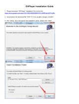
Page is loading ...

MICROCOMPUTER MN102H
MN102H75K/F75K/85K/F85K
LSI User’s Manual
Pub.No.22385-011E


PanaXSeries is a trademark of Matsushita Electric Industrial Co., Ltd.
The other corporation names, logotype and product names written in this book are trademarks or registered trademarks of their
corresponding corporations.
Request for your special attention and precautions in using the technical information
and semiconductors described in this book
(1) An export permit needs to be obtained from the competent authorities of the Japanese Government if any of
the products or technologies described in this book and controlled under the "Foreign Exchange and Foreign
Trade Law" is to be exported or taken out of Japan.
(2) The contents of this book are subject to change without notice in matters of improved function. When
finalizing your design, therefore, ask for the most up-to-date version in advance in order to check for any
changes.
(3) We are not liable for any damage arising out of the use of the contents of this book, or for any infringement
of patents or any other rights owned by a third party.
(4) No part of this book may be reprinted or reproduced by any means without written permission from our
company.
(5) This book deals with standard specification. Ask for the latest individual Product Standards or Specifications
in advance for more detailed information required for your design, purchasing and applications.
If you have any inquiries or questions about this book or our semiconductors, please contact one of our sales
offices listed at the back of this book.

Contents
MN102H75K/F75K LSI User Manual Panasonic Semiconductor Development Company
3
Panasonic
Contents
About This Manual . . . . . . . . . . . . . . . . . . . . . . . . . . . . . . . . . . . . . . . . . . . . . . . . . . . . . . . . . . . 16
Using This Manual. . . . . . . . . . . . . . . . . . . . . . . . . . . . . . . . . . . . . . . . . . . . . . . . . . . . . . . . . . . . . . . . . . 16
Text Conventions . . . . . . . . . . . . . . . . . . . . . . . . . . . . . . . . . . . . . . . . . . . . . . . . . . . . . . . . . . . . . . . . . . . 16
Register Conventions. . . . . . . . . . . . . . . . . . . . . . . . . . . . . . . . . . . . . . . . . . . . . . . . . . . . . . . . . . . . . . . . 16
Related Documents . . . . . . . . . . . . . . . . . . . . . . . . . . . . . . . . . . . . . . . . . . . . . . . . . . . . . . . . . . . . . . . . . 17
Questions and Comments . . . . . . . . . . . . . . . . . . . . . . . . . . . . . . . . . . . . . . . . . . . . . . . . . . . . . . . . . . . . 17
1 General Description . . . . . . . . . . . . . . . . . . . . . . . . . . . . . . . . . . . . . . . . . . . . . . . . . . . . . . . . . . 18
1.1 MN102H Series Overview. . . . . . . . . . . . . . . . . . . . . . . . . . . . . . . . . . . . . . . . . . . . . . . . . . . . . . . . . . . . 18
1.2 MN102H Series Features. . . . . . . . . . . . . . . . . . . . . . . . . . . . . . . . . . . . . . . . . . . . . . . . . . . . . . . . . . . . . 18
1.3 MN102H Series Description . . . . . . . . . . . . . . . . . . . . . . . . . . . . . . . . . . . . . . . . . . . . . . . . . . . . . . . . . . 21
1.4 General Specifications . . . . . . . . . . . . . . . . . . . . . . . . . . . . . . . . . . . . . . . . . . . . . . . . . . . . . . . . . . . . . . . 26
1.5 Block Diagram. . . . . . . . . . . . . . . . . . . . . . . . . . . . . . . . . . . . . . . . . . . . . . . . . . . . . . . . . . . . . . . . . . . . . 28
1.6 Pin Descriptions. . . . . . . . . . . . . . . . . . . . . . . . . . . . . . . . . . . . . . . . . . . . . . . . . . . . . . . . . . . . . . . . . . . . 30
1.6.1 MN102H85K Pin Description . . . . . . . . . . . . . . . . . . . . . . . . . . . . . . . . . . . . . . . . . . . . . . . . . . . . . . 30
1.6.2 MN102H75K Pin Description . . . . . . . . . . . . . . . . . . . . . . . . . . . . . . . . . . . . . . . . . . . . . . . . . . . . . . 31
1.7 Bus Interface . . . . . . . . . . . . . . . . . . . . . . . . . . . . . . . . . . . . . . . . . . . . . . . . . . . . . . . . . . . . . . . . . . . . . . 35
1.7.1 Description. . . . . . . . . . . . . . . . . . . . . . . . . . . . . . . . . . . . . . . . . . . . . . . . . . . . . . . . . . . . . . . . . . . . . 35
1.7.2 Bus Interface Control Registers . . . . . . . . . . . . . . . . . . . . . . . . . . . . . . . . . . . . . . . . . . . . . . . . . . . . . 36
2 Interrupts. . . . . . . . . . . . . . . . . . . . . . . . . . . . . . . . . . . . . . . . . . . . . . . . . . . . . . . . . . . . . . . . . . . 37
2.1 Description. . . . . . . . . . . . . . . . . . . . . . . . . . . . . . . . . . . . . . . . . . . . . . . . . . . . . . . . . . . . . . . . . . . . . . . . 37
2.2 Interrupt Setup Examples. . . . . . . . . . . . . . . . . . . . . . . . . . . . . . . . . . . . . . . . . . . . . . . . . . . . . . . . . . . . . 40
2.2.1 Setting Up an External Pin Interrupt . . . . . . . . . . . . . . . . . . . . . . . . . . . . . . . . . . . . . . . . . . . . . . . . . 40
2.2.2 Setting Up a Watchdog Timer Interrupt. . . . . . . . . . . . . . . . . . . . . . . . . . . . . . . . . . . . . . . . . . . . . . . 42
2.3 Interrupt Control Registers . . . . . . . . . . . . . . . . . . . . . . . . . . . . . . . . . . . . . . . . . . . . . . . . . . . . . . . . . . . 44
3 Low-Power Modes . . . . . . . . . . . . . . . . . . . . . . . . . . . . . . . . . . . . . . . . . . . . . . . . . . . . . . . . . . . 72
3.1 CPU Modes . . . . . . . . . . . . . . . . . . . . . . . . . . . . . . . . . . . . . . . . . . . . . . . . . . . . . . . . . . . . . . . . . . . . . . . 72
3.1.1 Description. . . . . . . . . . . . . . . . . . . . . . . . . . . . . . . . . . . . . . . . . . . . . . . . . . . . . . . . . . . . . . . . . . . . . 72
3.1.2 Exiting from SLOW Mode to NORMAL Mode . . . . . . . . . . . . . . . . . . . . . . . . . . . . . . . . . . . . . . . . 73
3.1.3 Notes on Invoking and Exiting STOP and HALT Modes . . . . . . . . . . . . . . . . . . . . . . . . . . . . . . . . . 74
3.2 Turning Individual Functions On and Off . . . . . . . . . . . . . . . . . . . . . . . . . . . . . . . . . . . . . . . . . . . . . . . . 75
3.3 CPU Control Register . . . . . . . . . . . . . . . . . . . . . . . . . . . . . . . . . . . . . . . . . . . . . . . . . . . . . . . . . . . . . . . 76
4 Timers . . . . . . . . . . . . . . . . . . . . . . . . . . . . . . . . . . . . . . . . . . . . . . . . . . . . . . . . . . . . . . . . . . . . . 77
4.1 8-Bit Timer Description. . . . . . . . . . . . . . . . . . . . . . . . . . . . . . . . . . . . . . . . . . . . . . . . . . . . . . . . . . . . . . 77
4.2 8-Bit Timer Features . . . . . . . . . . . . . . . . . . . . . . . . . . . . . . . . . . . . . . . . . . . . . . . . . . . . . . . . . . . . . . . . 78
4.3 8-Bit Timer Block Diagrams . . . . . . . . . . . . . . . . . . . . . . . . . . . . . . . . . . . . . . . . . . . . . . . . . . . . . . . . . . 79
4.4 8-Bit Timer Timing . . . . . . . . . . . . . . . . . . . . . . . . . . . . . . . . . . . . . . . . . . . . . . . . . . . . . . . . . . . . . . . . . 81
4.5 8-Bit Timer Setup Examples . . . . . . . . . . . . . . . . . . . . . . . . . . . . . . . . . . . . . . . . . . . . . . . . . . . . . . . . . . 82

Contents
Panasonic Semiconductor Development Company MN102H75K/F75K LSI User Manual
4
Panasonic
4.5.1 Setting Up an Event Counter Using Timer 0 . . . . . . . . . . . . . . . . . . . . . . . . . . . . . . . . . . . . . . . . . . . 82
4.5.2 Setting Up an Interval Timer Using Timers 1 and 2 . . . . . . . . . . . . . . . . . . . . . . . . . . . . . . . . . . . . . 84
4.6 8-Bit Timer Control Registers . . . . . . . . . . . . . . . . . . . . . . . . . . . . . . . . . . . . . . . . . . . . . . . . . . . . . . . . . 87
4.7 16-Bit Timer Description. . . . . . . . . . . . . . . . . . . . . . . . . . . . . . . . . . . . . . . . . . . . . . . . . . . . . . . . . . . . . 88
4.8 16-Bit Timer Features . . . . . . . . . . . . . . . . . . . . . . . . . . . . . . . . . . . . . . . . . . . . . . . . . . . . . . . . . . . . . . . 89
4.9 16-Bit Timer Block Diagrams . . . . . . . . . . . . . . . . . . . . . . . . . . . . . . . . . . . . . . . . . . . . . . . . . . . . . . . . . 90
4.10 16-Bit Timer Timing . . . . . . . . . . . . . . . . . . . . . . . . . . . . . . . . . . . . . . . . . . . . . . . . . . . . . . . . . . . . . . . . 90
4.11 16-Bit Timer Setup Examples . . . . . . . . . . . . . . . . . . . . . . . . . . . . . . . . . . . . . . . . . . . . . . . . . . . . . . . . . 94
4.11.1 Setting Up an Event Counter Using Timer 4 . . . . . . . . . . . . . . . . . . . . . . . . . . . . . . . . . . . . . . . . . . . 94
4.11.2 Setting Up a Single-Phase PWM Output Signal Using Timer 4 . . . . . . . . . . . . . . . . . . . . . . . . . . . . 96
4.11.3 Setting Up a Two-Phase PWM Output Signal Using Timer 4. . . . . . . . . . . . . . . . . . . . . . . . . . . . . 101
4.11.4 Setting Up a Single-Phase Capture Input Using Timer 4. . . . . . . . . . . . . . . . . . . . . . . . . . . . . . . . . 106
4.11.5 Setting Up a Two-Phase Capture Input Using Timer 4 . . . . . . . . . . . . . . . . . . . . . . . . . . . . . . . . . . 108
4.11.6 Setting Up a 4x Two-Phase Encoder Input Using Timer 5 . . . . . . . . . . . . . . . . . . . . . . . . . . . . . . . 111
4.11.7 Setting Up a 1x Two-Phase Encoder Input Using Timer 5 . . . . . . . . . . . . . . . . . . . . . . . . . . . . . . . 114
4.11.8 Setting Up a One-Shot Pulse Output Using Timer 5 . . . . . . . . . . . . . . . . . . . . . . . . . . . . . . . . . . . . 117
4.11.9 Setting Up an External Count Direction Controller Using Timer 5. . . . . . . . . . . . . . . . . . . . . . . . . 120
4.11.10 Setting Up External Reset Control Using Timer 5. . . . . . . . . . . . . . . . . . . . . . . . . . . . . . . . . . . . . . 123
4.12 16-Bit Timer Control Registers . . . . . . . . . . . . . . . . . . . . . . . . . . . . . . . . . . . . . . . . . . . . . . . . . . . . . . . 125
5 Serial Interfaces . . . . . . . . . . . . . . . . . . . . . . . . . . . . . . . . . . . . . . . . . . . . . . . . . . . . . . . . . . . . 127
5.1 Description. . . . . . . . . . . . . . . . . . . . . . . . . . . . . . . . . . . . . . . . . . . . . . . . . . . . . . . . . . . . . . . . . . . . . . . 127
5.2 Features . . . . . . . . . . . . . . . . . . . . . . . . . . . . . . . . . . . . . . . . . . . . . . . . . . . . . . . . . . . . . . . . . . . . . . . . . 127
5.3 Connecting the Serial Interfaces . . . . . . . . . . . . . . . . . . . . . . . . . . . . . . . . . . . . . . . . . . . . . . . . . . . . . . 128
5.3.1 Synchronous Serial Mode Connections. . . . . . . . . . . . . . . . . . . . . . . . . . . . . . . . . . . . . . . . . . . . . . 128
5.3.2 UART Mode Connections . . . . . . . . . . . . . . . . . . . . . . . . . . . . . . . . . . . . . . . . . . . . . . . . . . . . . . . . 128
5.3.3 I
2
C Mode Connection . . . . . . . . . . . . . . . . . . . . . . . . . . . . . . . . . . . . . . . . . . . . . . . . . . . . . . . . . . . 128
5.4 UART Mode Baud Rates . . . . . . . . . . . . . . . . . . . . . . . . . . . . . . . . . . . . . . . . . . . . . . . . . . . . . . . . . . . . 129
5.5 Serial Interface Timing . . . . . . . . . . . . . . . . . . . . . . . . . . . . . . . . . . . . . . . . . . . . . . . . . . . . . . . . . . . . . 129
5.5.1 Synchronous Serial Mode Timing . . . . . . . . . . . . . . . . . . . . . . . . . . . . . . . . . . . . . . . . . . . . . . . . . . 129
5.5.2 UART Mode Timing . . . . . . . . . . . . . . . . . . . . . . . . . . . . . . . . . . . . . . . . . . . . . . . . . . . . . . . . . . . . 130
5.6 Serial Interface Setup Examples . . . . . . . . . . . . . . . . . . . . . . . . . . . . . . . . . . . . . . . . . . . . . . . . . . . . . . 131
5.6.1 Setting Up UART Transmission Using Serial Interface 0 . . . . . . . . . . . . . . . . . . . . . . . . . . . . . . . . 131
5.6.2 Setting Up Synchronous Serial Reception Using Serial Interface 0 . . . . . . . . . . . . . . . . . . . . . . . . 134
5.6.3 Setting Up the Serial Interface Clock. . . . . . . . . . . . . . . . . . . . . . . . . . . . . . . . . . . . . . . . . . . . . . . . 135
5.6.4 Setting Up I
2
C Transmission Using Serial Interface 0 . . . . . . . . . . . . . . . . . . . . . . . . . . . . . . . . . . 137
5.6.5 Setting Up I
2
C Reception Using Serial Interface 0 . . . . . . . . . . . . . . . . . . . . . . . . . . . . . . . . . . . . . 139
5.7 Serial Interface Control Registers . . . . . . . . . . . . . . . . . . . . . . . . . . . . . . . . . . . . . . . . . . . . . . . . . . . . . 140
6 Analog-to-Digital Converter. . . . . . . . . . . . . . . . . . . . . . . . . . . . . . . . . . . . . . . . . . . . . . . . . . . 143
6.1 Description. . . . . . . . . . . . . . . . . . . . . . . . . . . . . . . . . . . . . . . . . . . . . . . . . . . . . . . . . . . . . . . . . . . . . . . 143
6.2 Features . . . . . . . . . . . . . . . . . . . . . . . . . . . . . . . . . . . . . . . . . . . . . . . . . . . . . . . . . . . . . . . . . . . . . . . . . 143
6.3 Block Diagram. . . . . . . . . . . . . . . . . . . . . . . . . . . . . . . . . . . . . . . . . . . . . . . . . . . . . . . . . . . . . . . . . . . . 144
6.4 A/D Conversion Timing. . . . . . . . . . . . . . . . . . . . . . . . . . . . . . . . . . . . . . . . . . . . . . . . . . . . . . . . . . . . . 144
6.4.1 Selecting the ADC Clock Source. . . . . . . . . . . . . . . . . . . . . . . . . . . . . . . . . . . . . . . . . . . . . . . . . . . 144

Contents
MN102H75K/F75K LSI User Manual Panasonic Semiconductor Development Company
5
Panasonic
6.4.2 Single Channel/Single Conversion Timing . . . . . . . . . . . . . . . . . . . . . . . . . . . . . . . . . . . . . . . . . . . 145
6.4.3 Multiple Channel/Single Conversion Timing . . . . . . . . . . . . . . . . . . . . . . . . . . . . . . . . . . . . . . . . . 145
6.4.4 Single Channel/Continuous Conversion Timing . . . . . . . . . . . . . . . . . . . . . . . . . . . . . . . . . . . . . . . 146
6.4.5 Multiple Channel/Continuous Conversion Timing . . . . . . . . . . . . . . . . . . . . . . . . . . . . . . . . . . . . . 146
6.5 ADC Setup Examples . . . . . . . . . . . . . . . . . . . . . . . . . . . . . . . . . . . . . . . . . . . . . . . . . . . . . . . . . . . . . . 147
6.5.1 Setting Up Software-Controlled Single-Channel A/D Conversion . . . . . . . . . . . . . . . . . . . . . . . . . 147
6.5.2 Setting Up Hardware-Controlled Intermittent Three-Channel A/D Conversion . . . . . . . . . . . . . . . 148
6.6 ADC Control Registers . . . . . . . . . . . . . . . . . . . . . . . . . . . . . . . . . . . . . . . . . . . . . . . . . . . . . . . . . . . . . 150
6.7 Caution about Analog-to-Digital Converter. . . . . . . . . . . . . . . . . . . . . . . . . . . . . . . . . . . . . . . . . . . . . . 152
7 On-Screen Display . . . . . . . . . . . . . . . . . . . . . . . . . . . . . . . . . . . . . . . . . . . . . . . . . . . . . . . . . . 153
7.1 Description. . . . . . . . . . . . . . . . . . . . . . . . . . . . . . . . . . . . . . . . . . . . . . . . . . . . . . . . . . . . . . . . . . . . . . . 153
7.2 Features . . . . . . . . . . . . . . . . . . . . . . . . . . . . . . . . . . . . . . . . . . . . . . . . . . . . . . . . . . . . . . . . . . . . . . . . . 153
7.3 Block Diagram. . . . . . . . . . . . . . . . . . . . . . . . . . . . . . . . . . . . . . . . . . . . . . . . . . . . . . . . . . . . . . . . . . . . 154
7.4 Power-Saving Considerations in the OSD Block. . . . . . . . . . . . . . . . . . . . . . . . . . . . . . . . . . . . . . . . . . 155
7.5 OSD Operation. . . . . . . . . . . . . . . . . . . . . . . . . . . . . . . . . . . . . . . . . . . . . . . . . . . . . . . . . . . . . . . . . . . . 156
7.5.1 OSD Clock. . . . . . . . . . . . . . . . . . . . . . . . . . . . . . . . . . . . . . . . . . . . . . . . . . . . . . . . . . . . . . . . . . . . 156
7.5.2 External Input Sync Signals. . . . . . . . . . . . . . . . . . . . . . . . . . . . . . . . . . . . . . . . . . . . . . . . . . . . . . . 156
7.5.3 Multi-Layer Format . . . . . . . . . . . . . . . . . . . . . . . . . . . . . . . . . . . . . . . . . . . . . . . . . . . . . . . . . . . . . 156
7.5.4 Output Pin Setup . . . . . . . . . . . . . . . . . . . . . . . . . . . . . . . . . . . . . . . . . . . . . . . . . . . . . . . . . . . . . . . 157
7.5.5 Microcontroller Interface. . . . . . . . . . . . . . . . . . . . . . . . . . . . . . . . . . . . . . . . . . . . . . . . . . . . . . . . . 157
7.5.6 VRAM . . . . . . . . . . . . . . . . . . . . . . . . . . . . . . . . . . . . . . . . . . . . . . . . . . . . . . . . . . . . . . . . . . . . . . . 157
7.5.7 Conditions for VRAM Writes . . . . . . . . . . . . . . . . . . . . . . . . . . . . . . . . . . . . . . . . . . . . . . . . . . . . . 158
7.6 Standard and Extended Display Modes. . . . . . . . . . . . . . . . . . . . . . . . . . . . . . . . . . . . . . . . . . . . . . . . . 159
7.6.1 Cursor Layer Display Modes. . . . . . . . . . . . . . . . . . . . . . . . . . . . . . . . . . . . . . . . . . . . . . . . . . . . . . 159
7.6.2 Graphics Layer Display Modes . . . . . . . . . . . . . . . . . . . . . . . . . . . . . . . . . . . . . . . . . . . . . . . . . . . . 160
7.7 Display Setup Examples . . . . . . . . . . . . . . . . . . . . . . . . . . . . . . . . . . . . . . . . . . . . . . . . . . . . . . . . . . . . 161
7.7.1 Setting Up the Graphics Layer. . . . . . . . . . . . . . . . . . . . . . . . . . . . . . . . . . . . . . . . . . . . . . . . . . . . . 161
7.7.2 Setting Up the Text Layer . . . . . . . . . . . . . . . . . . . . . . . . . . . . . . . . . . . . . . . . . . . . . . . . . . . . . . . . 163
7.8 VRAM . . . . . . . . . . . . . . . . . . . . . . . . . . . . . . . . . . . . . . . . . . . . . . . . . . . . . . . . . . . . . . . . . . . . . . . . . . 165
7.8.1 VRAM Operation. . . . . . . . . . . . . . . . . . . . . . . . . . . . . . . . . . . . . . . . . . . . . . . . . . . . . . . . . . . . . . . 165
7.8.2 VRAM Organization . . . . . . . . . . . . . . . . . . . . . . . . . . . . . . . . . . . . . . . . . . . . . . . . . . . . . . . . . . . . 169
7.8.3 Cautions about the number of display code set to VRAM. . . . . . . . . . . . . . . . . . . . . . . . . . . . . . . . 171
7.9 ROM. . . . . . . . . . . . . . . . . . . . . . . . . . . . . . . . . . . . . . . . . . . . . . . . . . . . . . . . . . . . . . . . . . . . . . . . . . . . 172
7.9.1 ROM Organization. . . . . . . . . . . . . . . . . . . . . . . . . . . . . . . . . . . . . . . . . . . . . . . . . . . . . . . . . . . . . . 172
7.9.2 Graphics ROM Organization in Different Color Modes . . . . . . . . . . . . . . . . . . . . . . . . . . . . . . . . . 173
7.10 Setting Up the OSD . . . . . . . . . . . . . . . . . . . . . . . . . . . . . . . . . . . . . . . . . . . . . . . . . . . . . . . . . . . . . . . . 178
7.10.1 Setting Up the OSD Display Colors. . . . . . . . . . . . . . . . . . . . . . . . . . . . . . . . . . . . . . . . . . . . . . . . . 178
7.10.2 Text Layer Functions . . . . . . . . . . . . . . . . . . . . . . . . . . . . . . . . . . . . . . . . . . . . . . . . . . . . . . . . . . . . 184
7.10.3 Display Sizes . . . . . . . . . . . . . . . . . . . . . . . . . . . . . . . . . . . . . . . . . . . . . . . . . . . . . . . . . . . . . . . . . . 187
7.10.4 Setting Up the OSD Display Position . . . . . . . . . . . . . . . . . . . . . . . . . . . . . . . . . . . . . . . . . . . . . . . 189
7.11 DMA and Interrupt Timing . . . . . . . . . . . . . . . . . . . . . . . . . . . . . . . . . . . . . . . . . . . . . . . . . . . . . . . . . . 191
7.12 Selecting the OSD Dot Clock . . . . . . . . . . . . . . . . . . . . . . . . . . . . . . . . . . . . . . . . . . . . . . . . . . . . . . . . 193
7.13 Controlling the Shuttering Effect. . . . . . . . . . . . . . . . . . . . . . . . . . . . . . . . . . . . . . . . . . . . . . . . . . . . . . 194
7.13.1 Controlling the Shuttered Area . . . . . . . . . . . . . . . . . . . . . . . . . . . . . . . . . . . . . . . . . . . . . . . . . . . . 194
7.13.2 Controlling Shutter Movement. . . . . . . . . . . . . . . . . . . . . . . . . . . . . . . . . . . . . . . . . . . . . . . . . . . . . 196

Contents
Panasonic Semiconductor Development Company MN102H75K/F75K LSI User Manual
6
Panasonic
7.13.3 Controlling Shuttering Effects . . . . . . . . . . . . . . . . . . . . . . . . . . . . . . . . . . . . . . . . . . . . . . . . . . . . . 198
7.13.4 Controlling Line Shuttering . . . . . . . . . . . . . . . . . . . . . . . . . . . . . . . . . . . . . . . . . . . . . . . . . . . . . . . 200
7.14 Field Detection Circuit. . . . . . . . . . . . . . . . . . . . . . . . . . . . . . . . . . . . . . . . . . . . . . . . . . . . . . . . . . . . . . 201
7.14.1 Block Diagram. . . . . . . . . . . . . . . . . . . . . . . . . . . . . . . . . . . . . . . . . . . . . . . . . . . . . . . . . . . . . . . . . 201
7.14.2 Description. . . . . . . . . . . . . . . . . . . . . . . . . . . . . . . . . . . . . . . . . . . . . . . . . . . . . . . . . . . . . . . . . . . . 201
7.14.3 Considerations for Interlaced Displays . . . . . . . . . . . . . . . . . . . . . . . . . . . . . . . . . . . . . . . . . . . . . . 202
7.15 OSD Registers . . . . . . . . . . . . . . . . . . . . . . . . . . . . . . . . . . . . . . . . . . . . . . . . . . . . . . . . . . . . . . . . . . . . 203
8 IR Remote Signal Receiver . . . . . . . . . . . . . . . . . . . . . . . . . . . . . . . . . . . . . . . . . . . . . . . . . . . 216
8.1 Description. . . . . . . . . . . . . . . . . . . . . . . . . . . . . . . . . . . . . . . . . . . . . . . . . . . . . . . . . . . . . . . . . . . . . . . 216
8.2 Block Diagram. . . . . . . . . . . . . . . . . . . . . . . . . . . . . . . . . . . . . . . . . . . . . . . . . . . . . . . . . . . . . . . . . . . . 217
8.3 IR Remote Signal Receiver Operation. . . . . . . . . . . . . . . . . . . . . . . . . . . . . . . . . . . . . . . . . . . . . . . . . . 218
8.3.1 Operating Modes . . . . . . . . . . . . . . . . . . . . . . . . . . . . . . . . . . . . . . . . . . . . . . . . . . . . . . . . . . . . . . . 218
8.3.2 Noise Filter. . . . . . . . . . . . . . . . . . . . . . . . . . . . . . . . . . . . . . . . . . . . . . . . . . . . . . . . . . . . . . . . . . . . 218
8.3.3 8-Bit Data Reception . . . . . . . . . . . . . . . . . . . . . . . . . . . . . . . . . . . . . . . . . . . . . . . . . . . . . . . . . . . . 219
8.3.4 Identifying the Data Format. . . . . . . . . . . . . . . . . . . . . . . . . . . . . . . . . . . . . . . . . . . . . . . . . . . . . . . 220
8.3.5 Generating Interrupts . . . . . . . . . . . . . . . . . . . . . . . . . . . . . . . . . . . . . . . . . . . . . . . . . . . . . . . . . . . . 221
8.3.5.1 Leader Detection . . . . . . . . . . . . . . . . . . . . . . . . . . . . . . . . . . . . . . . . . . . . . . . . . . . . . . . . . . . . 221
8.3.5.2 Trailer Detection. . . . . . . . . . . . . . . . . . . . . . . . . . . . . . . . . . . . . . . . . . . . . . . . . . . . . . . . . . . . . 221
8.3.5.3 8-Bit Data Reception Detection . . . . . . . . . . . . . . . . . . . . . . . . . . . . . . . . . . . . . . . . . . . . . . . . . 221
8.3.5.4 Pin Edge Detection. . . . . . . . . . . . . . . . . . . . . . . . . . . . . . . . . . . . . . . . . . . . . . . . . . . . . . . . . . . 221
8.3.6 Controlling the SLOW Mode. . . . . . . . . . . . . . . . . . . . . . . . . . . . . . . . . . . . . . . . . . . . . . . . . . . . . . 222
8.4 IR Remote Signal Receiver Control Registers. . . . . . . . . . . . . . . . . . . . . . . . . . . . . . . . . . . . . . . . . . . . 223
9 Closed-Caption Decoder . . . . . . . . . . . . . . . . . . . . . . . . . . . . . . . . . . . . . . . . . . . . . . . . . . . . . 227
9.1 Description. . . . . . . . . . . . . . . . . . . . . . . . . . . . . . . . . . . . . . . . . . . . . . . . . . . . . . . . . . . . . . . . . . . . . . . 227
9.2 Block Diagram. . . . . . . . . . . . . . . . . . . . . . . . . . . . . . . . . . . . . . . . . . . . . . . . . . . . . . . . . . . . . . . . . . . . 227
9.3 Functional Description. . . . . . . . . . . . . . . . . . . . . . . . . . . . . . . . . . . . . . . . . . . . . . . . . . . . . . . . . . . . . . 228
9.3.1 Analog-to-Digital Converter . . . . . . . . . . . . . . . . . . . . . . . . . . . . . . . . . . . . . . . . . . . . . . . . . . . . . . 228
9.3.2 Clamping Circuit . . . . . . . . . . . . . . . . . . . . . . . . . . . . . . . . . . . . . . . . . . . . . . . . . . . . . . . . . . . . . . . 229
9.3.3 Sync Separator Circuit . . . . . . . . . . . . . . . . . . . . . . . . . . . . . . . . . . . . . . . . . . . . . . . . . . . . . . . . . . . 230
9.3.3.1 HSYNC Separator . . . . . . . . . . . . . . . . . . . . . . . . . . . . . . . . . . . . . . . . . . . . . . . . . . . . . . . . . . . 232
9.3.3.2 VSYNC Separator . . . . . . . . . . . . . . . . . . . . . . . . . . . . . . . . . . . . . . . . . . . . . . . . . . . . . . . . . . . 233
9.3.3.3 Field Detection Circuit. . . . . . . . . . . . . . . . . . . . . . . . . . . . . . . . . . . . . . . . . . . . . . . . . . . . . . . . 233
9.3.4 Data Slicer . . . . . . . . . . . . . . . . . . . . . . . . . . . . . . . . . . . . . . . . . . . . . . . . . . . . . . . . . . . . . . . . . . . . 233
9.3.5 Controller and Sampling Circuit . . . . . . . . . . . . . . . . . . . . . . . . . . . . . . . . . . . . . . . . . . . . . . . . . . . 234
9.3.5.1 CRI Detection for Sampling Clock Generation . . . . . . . . . . . . . . . . . . . . . . . . . . . . . . . . . . . . . 235
9.3.5.2 Data Capture Control . . . . . . . . . . . . . . . . . . . . . . . . . . . . . . . . . . . . . . . . . . . . . . . . . . . . . . . . . 235
9.4 Closed-Caption Decoder Registers . . . . . . . . . . . . . . . . . . . . . . . . . . . . . . . . . . . . . . . . . . . . . . . . . . . . 236
10 Pulse Width Modulator. . . . . . . . . . . . . . . . . . . . . . . . . . . . . . . . . . . . . . . . . . . . . . . . . . . . . . . 249
10.1 Description. . . . . . . . . . . . . . . . . . . . . . . . . . . . . . . . . . . . . . . . . . . . . . . . . . . . . . . . . . . . . . . . . . . . . . . 249
10.2 Block Diagram. . . . . . . . . . . . . . . . . . . . . . . . . . . . . . . . . . . . . . . . . . . . . . . . . . . . . . . . . . . . . . . . . . . . 250
10.3 PWM Data Registers . . . . . . . . . . . . . . . . . . . . . . . . . . . . . . . . . . . . . . . . . . . . . . . . . . . . . . . . . . . . . . . 250

Contents
MN102H75K/F75K LSI User Manual Panasonic Semiconductor Development Company
7
Panasonic
11 I/O Ports. . . . . . . . . . . . . . . . . . . . . . . . . . . . . . . . . . . . . . . . . . . . . . . . . . . . . . . . . . . . . . . . . . . 251
11.1 Description. . . . . . . . . . . . . . . . . . . . . . . . . . . . . . . . . . . . . . . . . . . . . . . . . . . . . . . . . . . . . . . . . . . . . . . 251
11.2 I/O Port Circuit Diagrams . . . . . . . . . . . . . . . . . . . . . . . . . . . . . . . . . . . . . . . . . . . . . . . . . . . . . . . . . . . 252
11.3 I/O Port Control Registers . . . . . . . . . . . . . . . . . . . . . . . . . . . . . . . . . . . . . . . . . . . . . . . . . . . . . . . . . . . 277
12 ROM Correction . . . . . . . . . . . . . . . . . . . . . . . . . . . . . . . . . . . . . . . . . . . . . . . . . . . . . . . . . . . . 288
12.1 Description. . . . . . . . . . . . . . . . . . . . . . . . . . . . . . . . . . . . . . . . . . . . . . . . . . . . . . . . . . . . . . . . . . . . . . . 288
12.2 Block Diagram. . . . . . . . . . . . . . . . . . . . . . . . . . . . . . . . . . . . . . . . . . . . . . . . . . . . . . . . . . . . . . . . . . . . 289
12.3 Programming Considerations. . . . . . . . . . . . . . . . . . . . . . . . . . . . . . . . . . . . . . . . . . . . . . . . . . . . . . . . . 289
12.4 ROM Correction Control Registers . . . . . . . . . . . . . . . . . . . . . . . . . . . . . . . . . . . . . . . . . . . . . . . . . . . . 290
13 I
2
C Bus Controller. . . . . . . . . . . . . . . . . . . . . . . . . . . . . . . . . . . . . . . . . . . . . . . . . . . . . . . . . . . 293
13.1 Description. . . . . . . . . . . . . . . . . . . . . . . . . . . . . . . . . . . . . . . . . . . . . . . . . . . . . . . . . . . . . . . . . . . . . . . 293
13.2 Block Diagram. . . . . . . . . . . . . . . . . . . . . . . . . . . . . . . . . . . . . . . . . . . . . . . . . . . . . . . . . . . . . . . . . . . . 296
13.3 Functional Description. . . . . . . . . . . . . . . . . . . . . . . . . . . . . . . . . . . . . . . . . . . . . . . . . . . . . . . . . . . . . . 296
13.4 Setting Up the I
2
C Bus Connection. . . . . . . . . . . . . . . . . . . . . . . . . . . . . . . . . . . . . . . . . . . . . . . . . . . . 298
13.5 SDA and SCL Waveform Characteristics . . . . . . . . . . . . . . . . . . . . . . . . . . . . . . . . . . . . . . . . . . . . . . . 299
13.6 I
2
C Interface Setup Examples . . . . . . . . . . . . . . . . . . . . . . . . . . . . . . . . . . . . . . . . . . . . . . . . . . . . . . . . 300
13.6.1 Setting Up a Transition from Master Transmitter to Master Receiver. . . . . . . . . . . . . . . . . . . . . . . 300
13.6.1.1 Pre-configuring. . . . . . . . . . . . . . . . . . . . . . . . . . . . . . . . . . . . . . . . . . . . . . . . . . . . . . . . . . . . . . 300
13.6.1.2 Setting Up the First Interrupt . . . . . . . . . . . . . . . . . . . . . . . . . . . . . . . . . . . . . . . . . . . . . . . . . . . 300
13.6.1.3 Setting Up the Second Interrupt. . . . . . . . . . . . . . . . . . . . . . . . . . . . . . . . . . . . . . . . . . . . . . . . . 301
13.6.1.4 Setting Up the Third Interrupt . . . . . . . . . . . . . . . . . . . . . . . . . . . . . . . . . . . . . . . . . . . . . . . . . . 301
13.6.2 Setting Up a Transition from Slave Receiver to Slave Transmitter . . . . . . . . . . . . . . . . . . . . . . . . . 302
13.6.2.1 Pre-configuring. . . . . . . . . . . . . . . . . . . . . . . . . . . . . . . . . . . . . . . . . . . . . . . . . . . . . . . . . . . . . . 302
13.6.2.2 Setting Up the First Interrupt . . . . . . . . . . . . . . . . . . . . . . . . . . . . . . . . . . . . . . . . . . . . . . . . . . . 302
13.6.2.3 Setting Up the Second Interrupt. . . . . . . . . . . . . . . . . . . . . . . . . . . . . . . . . . . . . . . . . . . . . . . . . 303
13.6.2.4 Setting Up the Third Interrupt . . . . . . . . . . . . . . . . . . . . . . . . . . . . . . . . . . . . . . . . . . . . . . . . . . 303
13.7 I
2
C Bus Interface Registers . . . . . . . . . . . . . . . . . . . . . . . . . . . . . . . . . . . . . . . . . . . . . . . . . . . . . . . . . . 304
14 H Counter . . . . . . . . . . . . . . . . . . . . . . . . . . . . . . . . . . . . . . . . . . . . . . . . . . . . . . . . . . . . . . . . . 307
14.1 Description. . . . . . . . . . . . . . . . . . . . . . . . . . . . . . . . . . . . . . . . . . . . . . . . . . . . . . . . . . . . . . . . . . . . . . . 307
14.2 Block Diagram. . . . . . . . . . . . . . . . . . . . . . . . . . . . . . . . . . . . . . . . . . . . . . . . . . . . . . . . . . . . . . . . . . . . 307
14.3 H Counter Operation . . . . . . . . . . . . . . . . . . . . . . . . . . . . . . . . . . . . . . . . . . . . . . . . . . . . . . . . . . . . . . . 307
14.4 H Counter Control Registers . . . . . . . . . . . . . . . . . . . . . . . . . . . . . . . . . . . . . . . . . . . . . . . . . . . . . . . . . 310
Appendix A Register Map. . . . . . . . . . . . . . . . . . . . . . . . . . . . . . . . . . . . . . . . . . . . . . . . . . . . . . . . . . 312
Appendix B MN102HF75K Flash EEPROM Version . . . . . . . . . . . . . . . . . . . . . . . . . . . . . . . . . . . . . 316
B.1 Description. . . . . . . . . . . . . . . . . . . . . . . . . . . . . . . . . . . . . . . . . . . . . . . . . . . . . . . . . . . . . . . . . . . . . . . 316
B.2 Benefits . . . . . . . . . . . . . . . . . . . . . . . . . . . . . . . . . . . . . . . . . . . . . . . . . . . . . . . . . . . . . . . . . . . . . . . . . 317
B.3 Using the PROM Writer Mode . . . . . . . . . . . . . . . . . . . . . . . . . . . . . . . . . . . . . . . . . . . . . . . . . . . . . . . 317
B.4 Using the Onboard Serial Programming Mode . . . . . . . . . . . . . . . . . . . . . . . . . . . . . . . . . . . . . . . . . . . 319
B.4.1 Configuring the System for Onboard Serial Programming . . . . . . . . . . . . . . . . . . . . . . . . . . . . . . . 320

Contents
Panasonic Semiconductor Development Company MN102H75K/F75K LSI User Manual
8
Panasonic
B.4.2 Circuit Requirements for the Target Board . . . . . . . . . . . . . . . . . . . . . . . . . . . . . . . . . . . . . . . . . . . 321
B.4.3 Microcontroller Hardware Used in Onboard Serial Programming . . . . . . . . . . . . . . . . . . . . . . . . . 322
B.4.3.1 Serial Writer Interface Description . . . . . . . . . . . . . . . . . . . . . . . . . . . . . . . . . . . . . . . . . . . . . . 322
B.4.3.2 Serial Writer Interface Block Diagram . . . . . . . . . . . . . . . . . . . . . . . . . . . . . . . . . . . . . . . . . . . 322
B.4.4 Microcontroller Memory Map Used During Onboard Serial Programming . . . . . . . . . . . . . . . . . . 323
B.4.4.1 Flash ROM Address Space. . . . . . . . . . . . . . . . . . . . . . . . . . . . . . . . . . . . . . . . . . . . . . . . . . . . . 323
B.4.4.2 RAM Address Space . . . . . . . . . . . . . . . . . . . . . . . . . . . . . . . . . . . . . . . . . . . . . . . . . . . . . . . . . 324
B.4.5 Microcontroller Clock on the Target Board. . . . . . . . . . . . . . . . . . . . . . . . . . . . . . . . . . . . . . . . . . . 324
B.4.6 Setting Up the Onboard Serial Programming Mode . . . . . . . . . . . . . . . . . . . . . . . . . . . . . . . . . . . . 325
B.4.7 Branching to the User Program . . . . . . . . . . . . . . . . . . . . . . . . . . . . . . . . . . . . . . . . . . . . . . . . . . . . 327
B.4.7.1 Branching to the Reset Start Routine. . . . . . . . . . . . . . . . . . . . . . . . . . . . . . . . . . . . . . . . . . . . . 327
B.4.7.2 Branching to the Interrupt Start Routine . . . . . . . . . . . . . . . . . . . . . . . . . . . . . . . . . . . . . . . . . . 327
B.5 Reprogramming Flow . . . . . . . . . . . . . . . . . . . . . . . . . . . . . . . . . . . . . . . . . . . . . . . . . . . . . . . . . . . . . . 328
B.6 Programming Times. . . . . . . . . . . . . . . . . . . . . . . . . . . . . . . . . . . . . . . . . . . . . . . . . . . . . . . . . . . . . . . . 328

List of Tables
MN102H75K/F75K/85K/F85K LSI User Manual Panasonic Semiconductor Development Company
9
Panasonic
List of Tables
1-1 General Specifications. . . . . . . . . . . . . . . . . . . . . . . . . . . . . . . . . . . . . . . . . . . . . . . . . . . . . . . . . . . . . . . . . . 26
1-2 Block Diagram Explanation . . . . . . . . . . . . . . . . . . . . . . . . . . . . . . . . . . . . . . . . . . . . . . . . . . . . . . . . . . . . . 29
1-3 Pin Functions. . . . . . . . . . . . . . . . . . . . . . . . . . . . . . . . . . . . . . . . . . . . . . . . . . . . . . . . . . . . . . . . . . . . . . . . . 32
1-4 Wait Count Settings. . . . . . . . . . . . . . . . . . . . . . . . . . . . . . . . . . . . . . . . . . . . . . . . . . . . . . . . . . . . . . . . . . . . 36
2-1 Comparison of MN102H75K and MN102L35G Interrupt Features. . . . . . . . . . . . . . . . . . . . . . . . . . . . . . . 37
2-2 Handler Preprocessing. . . . . . . . . . . . . . . . . . . . . . . . . . . . . . . . . . . . . . . . . . . . . . . . . . . . . . . . . . . . . . . . . . 39
2-3 Handler Postprocessing . . . . . . . . . . . . . . . . . . . . . . . . . . . . . . . . . . . . . . . . . . . . . . . . . . . . . . . . . . . . . . . . . 39
2-4 Interrupt Control Registers . . . . . . . . . . . . . . . . . . . . . . . . . . . . . . . . . . . . . . . . . . . . . . . . . . . . . . . . . . . . . . 46
3-1 Peripheral Function On/Off Switches . . . . . . . . . . . . . . . . . . . . . . . . . . . . . . . . . . . . . . . . . . . . . . . . . . . . . . 75
3-2 CPU Mode Bit Settings . . . . . . . . . . . . . . . . . . . . . . . . . . . . . . . . . . . . . . . . . . . . . . . . . . . . . . . . . . . . . . . . . 76
4-1 8-Bit Timer Functions and Features . . . . . . . . . . . . . . . . . . . . . . . . . . . . . . . . . . . . . . . . . . . . . . . . . . . . . . . 78
4-2 8-Bit Timer Control Registers . . . . . . . . . . . . . . . . . . . . . . . . . . . . . . . . . . . . . . . . . . . . . . . . . . . . . . . . . . . . 87
4-3 16-Bit Timer Functions and Features . . . . . . . . . . . . . . . . . . . . . . . . . . . . . . . . . . . . . . . . . . . . . . . . . . . . . . 89
4-4 Count Direction for 4x Two-Phase Encoder Timing Example . . . . . . . . . . . . . . . . . . . . . . . . . . . . . . . . . . 113
4-5 Count Direction for 1x Two-Phase Encoder Timing Example . . . . . . . . . . . . . . . . . . . . . . . . . . . . . . . . . . 116
4-6 16-Bit Timer Control Registers . . . . . . . . . . . . . . . . . . . . . . . . . . . . . . . . . . . . . . . . . . . . . . . . . . . . . . . . . . 125
5-1 Serial Interface Functions and Features. . . . . . . . . . . . . . . . . . . . . . . . . . . . . . . . . . . . . . . . . . . . . . . . . . . . 127
5-2 Example Baud Rate Settings for the UART Mode . . . . . . . . . . . . . . . . . . . . . . . . . . . . . . . . . . . . . . . . . . . 129
5-3 Serial Interface Control Registers . . . . . . . . . . . . . . . . . . . . . . . . . . . . . . . . . . . . . . . . . . . . . . . . . . . . . . . . 140
6-1 ADC Functions and Features. . . . . . . . . . . . . . . . . . . . . . . . . . . . . . . . . . . . . . . . . . . . . . . . . . . . . . . . . . . . 143
6-2 ADC Control Registers . . . . . . . . . . . . . . . . . . . . . . . . . . . . . . . . . . . . . . . . . . . . . . . . . . . . . . . . . . . . . . . . 150
7-1 OSD Functions and Features. . . . . . . . . . . . . . . . . . . . . . . . . . . . . . . . . . . . . . . . . . . . . . . . . . . . . . . . . . . . 153
7-2 Power-Saving Control Bits for the OSD . . . . . . . . . . . . . . . . . . . . . . . . . . . . . . . . . . . . . . . . . . . . . . . . . . . 155
7-3 OSDPOFF and OSDREGE Settings . . . . . . . . . . . . . . . . . . . . . . . . . . . . . . . . . . . . . . . . . . . . . . . . . . . . . . 155
7-4 Associated Tiles for Cursor Tile Code Registers. . . . . . . . . . . . . . . . . . . . . . . . . . . . . . . . . . . . . . . . . . . . . 160
7-5 Example Graphics VRAM Settings. . . . . . . . . . . . . . . . . . . . . . . . . . . . . . . . . . . . . . . . . . . . . . . . . . . . . . . 161
7-6 Example Text VRAM Settings . . . . . . . . . . . . . . . . . . . . . . . . . . . . . . . . . . . . . . . . . . . . . . . . . . . . . . . . . . 163
7-7 VRAM Bit Allocation in Internal RAM . . . . . . . . . . . . . . . . . . . . . . . . . . . . . . . . . . . . . . . . . . . . . . . . . . . 165
7-8 Color Palette Registers. . . . . . . . . . . . . . . . . . . . . . . . . . . . . . . . . . . . . . . . . . . . . . . . . . . . . . . . . . . . . . . . . 178
7-9 RGB, YM, and YS Output Control Settings . . . . . . . . . . . . . . . . . . . . . . . . . . . . . . . . . . . . . . . . . . . . . . . . 181
7-10 OSD Dot Clock Source Settings . . . . . . . . . . . . . . . . . . . . . . . . . . . . . . . . . . . . . . . . . . . . . . . . . . . . . . . . . 193
7-11 OSD Dot Clock Division Settings. . . . . . . . . . . . . . . . . . . . . . . . . . . . . . . . . . . . . . . . . . . . . . . . . . . . . . . . 193
7-12 Bit Settings for Controlling the Shuttered Area . . . . . . . . . . . . . . . . . . . . . . . . . . . . . . . . . . . . . . . . . . . . . 194
7-13 Bit Settings for Controlling Shutter Movement. . . . . . . . . . . . . . . . . . . . . . . . . . . . . . . . . . . . . . . . . . . . . . 196
7-14 Bit Settings for Controlling Shuttering Effects . . . . . . . . . . . . . . . . . . . . . . . . . . . . . . . . . . . . . . . . . . . . . . 198
7-15 EOMON Output Criteria . . . . . . . . . . . . . . . . . . . . . . . . . . . . . . . . . . . . . . . . . . . . . . . . . . . . . . . . . . . . . . . 202
7-16 Cursor Vertical Size Settings . . . . . . . . . . . . . . . . . . . . . . . . . . . . . . . . . . . . . . . . . . . . . . . . . . . . . . . . . . . . 205
7-17 Graphics Vertical Size Settings . . . . . . . . . . . . . . . . . . . . . . . . . . . . . . . . . . . . . . . . . . . . . . . . . . . . . . . . . . 206
7-18 Text Vertical Size Settings. . . . . . . . . . . . . . . . . . . . . . . . . . . . . . . . . . . . . . . . . . . . . . . . . . . . . . . . . . . . . . 206
8-1 Logic Level Conditions for Data Formats. . . . . . . . . . . . . . . . . . . . . . . . . . . . . . . . . . . . . . . . . . . . . . . . . . 220
8-2 Long and Short Data Identification . . . . . . . . . . . . . . . . . . . . . . . . . . . . . . . . . . . . . . . . . . . . . . . . . . . . . . . 220
8-3 Leader Detection Conditions. . . . . . . . . . . . . . . . . . . . . . . . . . . . . . . . . . . . . . . . . . . . . . . . . . . . . . . . . . . . 221
8-4 Differences between SLOW and NORMAL Modes. . . . . . . . . . . . . . . . . . . . . . . . . . . . . . . . . . . . . . . . . . 222

List of Tables
Panasonic Semiconductor Development Company MN102H75K/F75K/85K/F85K LSI User Manual
10
Panasonic
8-5 IR Remote Signal Receiver Registers . . . . . . . . . . . . . . . . . . . . . . . . . . . . . . . . . . . . . . . . . . . . . . . . . . . . . 223
8-6 HEAMA and 5-/6-Bit Data Pulse Widths . . . . . . . . . . . . . . . . . . . . . . . . . . . . . . . . . . . . . . . . . . . . . . . . . . 223
9-1 Pins Used for CCD0 and CCD1 . . . . . . . . . . . . . . . . . . . . . . . . . . . . . . . . . . . . . . . . . . . . . . . . . . . . . . . . . 227
9-2 Caption decoder register setting . . . . . . . . . . . . . . . . . . . . . . . . . . . . . . . . . . . . . . . . . . . . . . . . . . . . . . . . . 229
9-3 Clamping Reference and Compare Levels . . . . . . . . . . . . . . . . . . . . . . . . . . . . . . . . . . . . . . . . . . . . . . . . . 229
9-4 Current Level Control . . . . . . . . . . . . . . . . . . . . . . . . . . . . . . . . . . . . . . . . . . . . . . . . . . . . . . . . . . . . . . . . . 230
9-5 Control Registers for Clamping Circuit. . . . . . . . . . . . . . . . . . . . . . . . . . . . . . . . . . . . . . . . . . . . . . . . . . . . 230
9-6 Control Registers for Sync Separator Circuit . . . . . . . . . . . . . . . . . . . . . . . . . . . . . . . . . . . . . . . . . . . . . . . 232
9-7 Control Registers for Data Slicer. . . . . . . . . . . . . . . . . . . . . . . . . . . . . . . . . . . . . . . . . . . . . . . . . . . . . . . . . 234
9-8 Control Registers for Controller and Sampling Circuit. . . . . . . . . . . . . . . . . . . . . . . . . . . . . . . . . . . . . . . . 234
9-9 Closed-Caption Decoder Register . . . . . . . . . . . . . . . . . . . . . . . . . . . . . . . . . . . . . . . . . . . . . . . . . . . . . . . . 236
10-1 Register Settings for Internal PWM Pullup. . . . . . . . . . . . . . . . . . . . . . . . . . . . . . . . . . . . . . . . . . . . . . . . . 249
11-1 I/O Port Pins . . . . . . . . . . . . . . . . . . . . . . . . . . . . . . . . . . . . . . . . . . . . . . . . . . . . . . . . . . . . . . . . . . . . . . . . 251
12-1 ROM Correction Address Match and Data Registers . . . . . . . . . . . . . . . . . . . . . . . . . . . . . . . . . . . . . . . . . 290
13-1 I
2
C Bus Terminology. . . . . . . . . . . . . . . . . . . . . . . . . . . . . . . . . . . . . . . . . . . . . . . . . . . . . . . . . . . . . . . . . . 293
13-2 Operating Modes for Devices on an I
2
C Bus . . . . . . . . . . . . . . . . . . . . . . . . . . . . . . . . . . . . . . . . . . . . . . . 294
13-3 Control Registers for Clamping Circuit. . . . . . . . . . . . . . . . . . . . . . . . . . . . . . . . . . . . . . . . . . . . . . . . . . . . 296
13-4 Registers Settings for SDA0/SCL0 or SDA1/SCL1 Ports. . . . . . . . . . . . . . . . . . . . . . . . . . . . . . . . . . . . . . 298
13-5 SDA and SCL Waveform Characteristics . . . . . . . . . . . . . . . . . . . . . . . . . . . . . . . . . . . . . . . . . . . . . . . . . . 299
13-6 STA and STO Settings. . . . . . . . . . . . . . . . . . . . . . . . . . . . . . . . . . . . . . . . . . . . . . . . . . . . . . . . . . . . . . . . . 304
14-1 H Counter Pins. . . . . . . . . . . . . . . . . . . . . . . . . . . . . . . . . . . . . . . . . . . . . . . . . . . . . . . . . . . . . . . . . . . . . . . 308
A-1 Register Map: x’007E00’ to x’007FFF’ . . . . . . . . . . . . . . . . . . . . . . . . . . . . . . . . . . . . . . . . . . . . . . . . . . . 312
A-2 Register Map: x’00FC00’ to x’00FDFF’. . . . . . . . . . . . . . . . . . . . . . . . . . . . . . . . . . . . . . . . . . . . . . . . . . . 313
A-3 Register Map: x’00FE00’ to x’00FFFF’ . . . . . . . . . . . . . . . . . . . . . . . . . . . . . . . . . . . . . . . . . . . . . . . . . . . 314
B-1 Programmable Areas in Each Programming Mode. . . . . . . . . . . . . . . . . . . . . . . . . . . . . . . . . . . . . . . . . . . 316
B-2 PROM Writer Hardware . . . . . . . . . . . . . . . . . . . . . . . . . . . . . . . . . . . . . . . . . . . . . . . . . . . . . . . . . . . . . . . 318
B-3 Pin Descriptions for Target Board–Serial Writer Connection . . . . . . . . . . . . . . . . . . . . . . . . . . . . . . . . . . 321
B-4 Flash ROM Address Space in Serial Programming Mode . . . . . . . . . . . . . . . . . . . . . . . . . . . . . . . . . . . . . 323
B-5 RAM Address Space in Serial Programming Mode . . . . . . . . . . . . . . . . . . . . . . . . . . . . . . . . . . . . . . . . . . 324
B-6 Microcontroller Clock Frequencies during Serial Programming . . . . . . . . . . . . . . . . . . . . . . . . . . . . . . . . 324
B-7 Programming Times for PROM and Serial Writers. . . . . . . . . . . . . . . . . . . . . . . . . . . . . . . . . . . . . . . . . . . 328

List of Figures
MN102H75K/F75K/85K/F85K LSI User Manual Panasonic Semiconductor Development Company
11
Panasonic
List of Figures
1-1 Conventional vs. MN102H Series Code Assignments . . . . . . . . . . . . . . . . . . . . . . . . . . . . . . . . . . . . . . . . . 19
1-2 Three-Stage Pipeline . . . . . . . . . . . . . . . . . . . . . . . . . . . . . . . . . . . . . . . . . . . . . . . . . . . . . . . . . . . . . . . . . . . 19
1-3 MN102H Series Interrupt Servicing . . . . . . . . . . . . . . . . . . . . . . . . . . . . . . . . . . . . . . . . . . . . . . . . . . . . . . . 20
1-4 Internal Registers, Memory, and Special Function Registers . . . . . . . . . . . . . . . . . . . . . . . . . . . . . . . . . . . . 23
1-5 Address Space . . . . . . . . . . . . . . . . . . . . . . . . . . . . . . . . . . . . . . . . . . . . . . . . . . . . . . . . . . . . . . . . . . . . . . . . 24
1-6 Interrupt Controller Configuration . . . . . . . . . . . . . . . . . . . . . . . . . . . . . . . . . . . . . . . . . . . . . . . . . . . . . . . . 25
1-7 Interrupt Servicing Sequence. . . . . . . . . . . . . . . . . . . . . . . . . . . . . . . . . . . . . . . . . . . . . . . . . . . . . . . . . . . . . 25
1-8 Functional Block Diagram. . . . . . . . . . . . . . . . . . . . . . . . . . . . . . . . . . . . . . . . . . . . . . . . . . . . . . . . . . . . . . . 28
1-9 MN102H85K Pin Configuration in Single-Chip Mode. . . . . . . . . . . . . . . . . . . . . . . . . . . . . . . . . . . . . . . . . 30
1-10 MN102H75K Pin Configuration in Single-Chip Mode. . . . . . . . . . . . . . . . . . . . . . . . . . . . . . . . . . . . . . . . . 31
1-11 Power Supply Wiring. . . . . . . . . . . . . . . . . . . . . . . . . . . . . . . . . . . . . . . . . . . . . . . . . . . . . . . . . . . . . . . . . . . 34
1-12 OSC1and OSC2 Connection Examples. . . . . . . . . . . . . . . . . . . . . . . . . . . . . . . . . . . . . . . . . . . . . . . . . . . . . 34
1-13 Reset Pin Connection Example 1 . . . . . . . . . . . . . . . . . . . . . . . . . . . . . . . . . . . . . . . . . . . . . . . . . . . . . . . . . 34
1-14 OSDXI and OSDXO Connection Examples. . . . . . . . . . . . . . . . . . . . . . . . . . . . . . . . . . . . . . . . . . . . . . . . . 34
1-15 Memory Space in External Extension Mode. . . . . . . . . . . . . . . . . . . . . . . . . . . . . . . . . . . . . . . . . . . . . . . . . 35
2-1 Interrupt Controller Block Diagram . . . . . . . . . . . . . . . . . . . . . . . . . . . . . . . . . . . . . . . . . . . . . . . . . . . . . . . 37
2-2 Interrupt Vector Group and Class Assignments. . . . . . . . . . . . . . . . . . . . . . . . . . . . . . . . . . . . . . . . . . . . . . . 38
2-3 Interrupt Servicing Time . . . . . . . . . . . . . . . . . . . . . . . . . . . . . . . . . . . . . . . . . . . . . . . . . . . . . . . . . . . . . . . . 39
2-4 Block Diagram of External Pin Interrupt. . . . . . . . . . . . . . . . . . . . . . . . . . . . . . . . . . . . . . . . . . . . . . . . . . . . 40
2-5 Timing for External Pin Interrupt Setup (Example) . . . . . . . . . . . . . . . . . . . . . . . . . . . . . . . . . . . . . . . . . . . 41
2-6 Block Diagram of Watchdog Timer Interrupt . . . . . . . . . . . . . . . . . . . . . . . . . . . . . . . . . . . . . . . . . . . . . . . . 42
2-7 Timing for Watchdog Timer Interrupt Setup (Example) . . . . . . . . . . . . . . . . . . . . . . . . . . . . . . . . . . . . . . . . 43
3-1 CPU State Changes . . . . . . . . . . . . . . . . . . . . . . . . . . . . . . . . . . . . . . . . . . . . . . . . . . . . . . . . . . . . . . . . . . . . 72
3-2 CPU Clock Switch (NORMAL/SLOW Modes) . . . . . . . . . . . . . . . . . . . . . . . . . . . . . . . . . . . . . . . . . . . . . . 73
4-1 Timer Configuration Examples . . . . . . . . . . . . . . . . . . . . . . . . . . . . . . . . . . . . . . . . . . . . . . . . . . . . . . . . . . . 77
4-2 Block Diagram of 8-Bit Timers. . . . . . . . . . . . . . . . . . . . . . . . . . . . . . . . . . . . . . . . . . . . . . . . . . . . . . . . . . . 77
4-3 Timer 0 Block Diagram. . . . . . . . . . . . . . . . . . . . . . . . . . . . . . . . . . . . . . . . . . . . . . . . . . . . . . . . . . . . . . . . . 79
4-4 Timer 1 Block Diagram. . . . . . . . . . . . . . . . . . . . . . . . . . . . . . . . . . . . . . . . . . . . . . . . . . . . . . . . . . . . . . . . . 79
4-5 Timer 2 Block Diagram. . . . . . . . . . . . . . . . . . . . . . . . . . . . . . . . . . . . . . . . . . . . . . . . . . . . . . . . . . . . . . . . . 80
4-6 Timer 3 Block Diagram. . . . . . . . . . . . . . . . . . . . . . . . . . . . . . . . . . . . . . . . . . . . . . . . . . . . . . . . . . . . . . . . . 80
4-7 Event Timer Input Timing (8-Bit Timers) . . . . . . . . . . . . . . . . . . . . . . . . . . . . . . . . . . . . . . . . . . . . . . . . . . . 81
4-8 Clock Output and Interval Timer Timing (8-Bit Timers) . . . . . . . . . . . . . . . . . . . . . . . . . . . . . . . . . . . . . . . 81
4-9 Block Diagram of Event Counter Using Timer 0 . . . . . . . . . . . . . . . . . . . . . . . . . . . . . . . . . . . . . . . . . . . . . 82
4-10 Event Counter Timing (Timer 0) . . . . . . . . . . . . . . . . . . . . . . . . . . . . . . . . . . . . . . . . . . . . . . . . . . . . . . . . . . 83
4-11 Configuration Example of Interval Timer Using Timers 1 and 2 . . . . . . . . . . . . . . . . . . . . . . . . . . . . . . . . . 84
4-12 Block Diagram of Interval Timer Using Timers 1 and 2. . . . . . . . . . . . . . . . . . . . . . . . . . . . . . . . . . . . . . . . 84
4-13 Interval Timer Timing (Timers 1 and 2) . . . . . . . . . . . . . . . . . . . . . . . . . . . . . . . . . . . . . . . . . . . . . . . . . . . . 86
4-14 Block Diagram of 16-Bit Timers. . . . . . . . . . . . . . . . . . . . . . . . . . . . . . . . . . . . . . . . . . . . . . . . . . . . . . . . . . 88
4-15 Timer 4 Block Diagram. . . . . . . . . . . . . . . . . . . . . . . . . . . . . . . . . . . . . . . . . . . . . . . . . . . . . . . . . . . . . . . . . 90
4-16 Timer 5 Block Diagram. . . . . . . . . . . . . . . . . . . . . . . . . . . . . . . . . . . . . . . . . . . . . . . . . . . . . . . . . . . . . . . . . 90
4-17 Single-Phase PWM Output Timing (16-Bit Timers). . . . . . . . . . . . . . . . . . . . . . . . . . . . . . . . . . . . . . . . . . . 90
4-18 Single-Phase PWM Output Timing with Data Change (16-Bit Timers). . . . . . . . . . . . . . . . . . . . . . . . . . . . 91
4-19 Two-Phase PWM Output Timing (16-Bit Timers) . . . . . . . . . . . . . . . . . . . . . . . . . . . . . . . . . . . . . . . . . . . . 91

List of Figures
Panasonic Semiconductor Development Company MN102H75K/F75K/85K/F85K LSI User Manual
12
Panasonic
4-20 One-Shot Pulse Output Timing (16-Bit Timers) . . . . . . . . . . . . . . . . . . . . . . . . . . . . . . . . . . . . . . . . . . . . . . 91
4-21 External Count Direction Control Timing (16-Bit Timers). . . . . . . . . . . . . . . . . . . . . . . . . . . . . . . . . . . . . . 92
4-22 Event Timer Input Timing (16-Bit Timers) . . . . . . . . . . . . . . . . . . . . . . . . . . . . . . . . . . . . . . . . . . . . . . . . . . 92
4-23 Single-Phase Capture Input Timing (16-Bit Timers). . . . . . . . . . . . . . . . . . . . . . . . . . . . . . . . . . . . . . . . . . . 92
4-24 Two-Phase Capture Input Timing (16-Bit Timers) . . . . . . . . . . . . . . . . . . . . . . . . . . . . . . . . . . . . . . . . . . . . 93
4-25 Two-Phase 4x Encoder Timing (16-Bit Timers) . . . . . . . . . . . . . . . . . . . . . . . . . . . . . . . . . . . . . . . . . . . . . . 93
4-26 Two-Phase 1x Encoder Timing (16-Bit Timers) . . . . . . . . . . . . . . . . . . . . . . . . . . . . . . . . . . . . . . . . . . . . . . 93
4-27 Block Diagram of Event Counter Using Timer 4 . . . . . . . . . . . . . . . . . . . . . . . . . . . . . . . . . . . . . . . . . . . . . 94
4-28 Event Counter Timing (Timer 4) . . . . . . . . . . . . . . . . . . . . . . . . . . . . . . . . . . . . . . . . . . . . . . . . . . . . . . . . . . 95
4-29 Block Diagram of Single-Phase PWM Output Using Timer 4 . . . . . . . . . . . . . . . . . . . . . . . . . . . . . . . . . . . 96
4-30 Single-Phase PWM Output Timing (Timer 4). . . . . . . . . . . . . . . . . . . . . . . . . . . . . . . . . . . . . . . . . . . . . . . . 99
4-31 Single-Phase PWM Output Timing with Dynamic Duty Changes (Timer 4). . . . . . . . . . . . . . . . . . . . . . . 100
4-32 Block Diagram of Two-Phase PWM Output Using Timer 4. . . . . . . . . . . . . . . . . . . . . . . . . . . . . . . . . . . . 101
4-33 Two-Phase PWM Output Timing (Timer 4) . . . . . . . . . . . . . . . . . . . . . . . . . . . . . . . . . . . . . . . . . . . . . . . . 104
4-34 Two-Phase PWM Output Timing with Dynamic Duty Changes (Timer 4). . . . . . . . . . . . . . . . . . . . . . . . . 105
4-35 Block Diagram of Single-Phase Capture Input Using Timer 4. . . . . . . . . . . . . . . . . . . . . . . . . . . . . . . . . . 106
4-36 Single-Phase Capture Input Timing (Timer 4) . . . . . . . . . . . . . . . . . . . . . . . . . . . . . . . . . . . . . . . . . . . . . . 107
4-37 Block Diagram of Two-Phase Capture Input Using Timer 4. . . . . . . . . . . . . . . . . . . . . . . . . . . . . . . . . . . . 108
4-38 Two-Phase Capture Input Timing (Timer 4) . . . . . . . . . . . . . . . . . . . . . . . . . . . . . . . . . . . . . . . . . . . . . . . . 110
4-39 Block Diagram of 4x Two-Phase Capture Input Using Timer 5 . . . . . . . . . . . . . . . . . . . . . . . . . . . . . . . . . 111
4-40 Configuration Example 1 of 4x Two-Phase Capture Input Using Timer 5 . . . . . . . . . . . . . . . . . . . . . . . . . 111
4-41 Configuration Example 2 of 4x Two-Phase Capture Input Using Timer 5 . . . . . . . . . . . . . . . . . . . . . . . . . 111
4-42 4x Two-Phase Encoder Input Timing (Timer 5) . . . . . . . . . . . . . . . . . . . . . . . . . . . . . . . . . . . . . . . . . . . . . 113
4-43 Block Diagram of 1x Two-Phase Capture Input Using Timer 5 . . . . . . . . . . . . . . . . . . . . . . . . . . . . . . . . . 114
4-44 Configuration Example 1 of 1x Two-Phase Capture Input Using Timer 5 . . . . . . . . . . . . . . . . . . . . . . . . . 114
4-45 Configuration Example 2 of 1x Two-Phase Capture Input Using Timer 5 . . . . . . . . . . . . . . . . . . . . . . . . . 114
4-46 1x Two-Phase Encoder Input Timing (Timer 5) . . . . . . . . . . . . . . . . . . . . . . . . . . . . . . . . . . . . . . . . . . . . . 116
4-47 Block Diagram of One-Shot Pulse Output Using Timer 5 . . . . . . . . . . . . . . . . . . . . . . . . . . . . . . . . . . . . . 117
4-48 One-Shot Pulse Output Timing (Timer 5). . . . . . . . . . . . . . . . . . . . . . . . . . . . . . . . . . . . . . . . . . . . . . . . . . 119
4-49 Block Diagram of External Count Direction Control Using Timer 5 . . . . . . . . . . . . . . . . . . . . . . . . . . . . . 120
4-50 Configuration Example of External Count Direction Control Using Timer 5. . . . . . . . . . . . . . . . . . . . . . . 120
4-51 External Count Direction Control Timing (Timer 5). . . . . . . . . . . . . . . . . . . . . . . . . . . . . . . . . . . . . . . . . . 122
4-52 Block Diagram of External Reset Control Using Timer 5. . . . . . . . . . . . . . . . . . . . . . . . . . . . . . . . . . . . . . 123
4-53 External Reset Control Timing (Timer 5) . . . . . . . . . . . . . . . . . . . . . . . . . . . . . . . . . . . . . . . . . . . . . . . . . . 124
5-1 Serial Interface Configuration Example . . . . . . . . . . . . . . . . . . . . . . . . . . . . . . . . . . . . . . . . . . . . . . . . . . . 127
5-2 Synchronous Serial Mode Connections. . . . . . . . . . . . . . . . . . . . . . . . . . . . . . . . . . . . . . . . . . . . . . . . . . . . 128
5-3 UART Mode Connections . . . . . . . . . . . . . . . . . . . . . . . . . . . . . . . . . . . . . . . . . . . . . . . . . . . . . . . . . . . . . . 128
5-4 I
2
C Mode Connection . . . . . . . . . . . . . . . . . . . . . . . . . . . . . . . . . . . . . . . . . . . . . . . . . . . . . . . . . . . . . . . . . 128
5-5 Synchronous Serial Transmission Timing. . . . . . . . . . . . . . . . . . . . . . . . . . . . . . . . . . . . . . . . . . . . . . . . . . 129
5-6 Synchronous Serial Reception Timing . . . . . . . . . . . . . . . . . . . . . . . . . . . . . . . . . . . . . . . . . . . . . . . . . . . . 130
5-7 UART Transmission Timing . . . . . . . . . . . . . . . . . . . . . . . . . . . . . . . . . . . . . . . . . . . . . . . . . . . . . . . . . . . . 130
5-8 UART Reception Timing. . . . . . . . . . . . . . . . . . . . . . . . . . . . . . . . . . . . . . . . . . . . . . . . . . . . . . . . . . . . . . . 130
5-9 Block Diagram of UART Transmission Using Serial Interface 0 . . . . . . . . . . . . . . . . . . . . . . . . . . . . . . . . 131
5-10 UART Transmission Timing (Serial Interface 0). . . . . . . . . . . . . . . . . . . . . . . . . . . . . . . . . . . . . . . . . . . . . 133
5-11 Block Diagram of Serial Interface Clock . . . . . . . . . . . . . . . . . . . . . . . . . . . . . . . . . . . . . . . . . . . . . . . . . . 135

List of Figures
MN102H75K/F75K/85K/F85K LSI User Manual Panasonic Semiconductor Development Company
13
Panasonic
5-12 Serial Interface Clock Timing . . . . . . . . . . . . . . . . . . . . . . . . . . . . . . . . . . . . . . . . . . . . . . . . . . . . . . . . . . . 136
5-13 Master Transmitter Timing in I
2
C Mode (with ACK). . . . . . . . . . . . . . . . . . . . . . . . . . . . . . . . . . . . . . . . . 138
5-14 Master Receiver Timing in I
2
C Mode (with ACK) . . . . . . . . . . . . . . . . . . . . . . . . . . . . . . . . . . . . . . . . . . . 139
6-1 ADC Architecture . . . . . . . . . . . . . . . . . . . . . . . . . . . . . . . . . . . . . . . . . . . . . . . . . . . . . . . . . . . . . . . . . . . . 143
6-2 ADC Block Diagram. . . . . . . . . . . . . . . . . . . . . . . . . . . . . . . . . . . . . . . . . . . . . . . . . . . . . . . . . . . . . . . . . . 144
6-3 ADC Timing . . . . . . . . . . . . . . . . . . . . . . . . . . . . . . . . . . . . . . . . . . . . . . . . . . . . . . . . . . . . . . . . . . . . . . . . 144
6-4 Single Channel/Single Conversion Timing . . . . . . . . . . . . . . . . . . . . . . . . . . . . . . . . . . . . . . . . . . . . . . . . . 145
6-5 Multiple Channel/Single Conversion Timing . . . . . . . . . . . . . . . . . . . . . . . . . . . . . . . . . . . . . . . . . . . . . . . 145
6-6 Single Channel/Continuous Conversion Timing . . . . . . . . . . . . . . . . . . . . . . . . . . . . . . . . . . . . . . . . . . . . . 146
6-7 Multiple Channel/Continuous Conversion Timing . . . . . . . . . . . . . . . . . . . . . . . . . . . . . . . . . . . . . . . . . . . 146
6-8 Single-Channel A/D Conversion . . . . . . . . . . . . . . . . . . . . . . . . . . . . . . . . . . . . . . . . . . . . . . . . . . . . . . . . . 147
6-9 Timing of Software-Controlled Single-Channel A/D Conversion. . . . . . . . . . . . . . . . . . . . . . . . . . . . . . . . 148
6-10 Multiple-Channel A/D Conversion . . . . . . . . . . . . . . . . . . . . . . . . . . . . . . . . . . . . . . . . . . . . . . . . . . . . . . . 148
6-11 Timing of Hardware-Controlled Intermittent Three-Channel A/D Conversion . . . . . . . . . . . . . . . . . . . . . 150
6-12 Cautions on Analog-to-Digital Converter . . . . . . . . . . . . . . . . . . . . . . . . . . . . . . . . . . . . . . . . . . . . . . . . . . 152
7-1 OSD Block Diagram . . . . . . . . . . . . . . . . . . . . . . . . . . . . . . . . . . . . . . . . . . . . . . . . . . . . . . . . . . . . . . . . . . 154
7-2 Cursor Tiles in Standard and Extended Modes . . . . . . . . . . . . . . . . . . . . . . . . . . . . . . . . . . . . . . . . . . . . . . 159
7-3 Graphic Tiles in Standard and Extended Modes . . . . . . . . . . . . . . . . . . . . . . . . . . . . . . . . . . . . . . . . . . . . . 160
7-4 Graphics Display Example . . . . . . . . . . . . . . . . . . . . . . . . . . . . . . . . . . . . . . . . . . . . . . . . . . . . . . . . . . . . . 162
7-5 Text Display Example . . . . . . . . . . . . . . . . . . . . . . . . . . . . . . . . . . . . . . . . . . . . . . . . . . . . . . . . . . . . . . . . . 164
7-6 VRAM Organization (When GEXTE = 0) . . . . . . . . . . . . . . . . . . . . . . . . . . . . . . . . . . . . . . . . . . . . . . . . . 169
7-7 Graphics VRAM Organization for Two Modes. . . . . . . . . . . . . . . . . . . . . . . . . . . . . . . . . . . . . . . . . . . . . . 170
7-8 Timing for OSD data . . . . . . . . . . . . . . . . . . . . . . . . . . . . . . . . . . . . . . . . . . . . . . . . . . . . . . . . . . . . . . . . . . 171
7-9 ROM Organization. . . . . . . . . . . . . . . . . . . . . . . . . . . . . . . . . . . . . . . . . . . . . . . . . . . . . . . . . . . . . . . . . . . . 172
7-10 Graphics ROM Setup Example for a Single Line . . . . . . . . . . . . . . . . . . . . . . . . . . . . . . . . . . . . . . . . . . . . 173
7-11 Graphics ROM in the Four Color Modes (16W x 16H Tiles) . . . . . . . . . . . . . . . . . . . . . . . . . . . . . . . . . . . 174
7-12 Graphics ROM in the Four Color Modes (16W x 18H Tiles) . . . . . . . . . . . . . . . . . . . . . . . . . . . . . . . . . . . 175
7-13 Graphics ROM Organization in 16-Color Mode (16W x 16H Tiles) . . . . . . . . . . . . . . . . . . . . . . . . . . . . . 176
7-14 Graphics ROM Organization in 8-Color Mode (16W x 16H Tiles) . . . . . . . . . . . . . . . . . . . . . . . . . . . . . . 176
7-15 Graphics ROM Organization in 4-Color Mode (16W x 16H Tiles) . . . . . . . . . . . . . . . . . . . . . . . . . . . . . . 176
7-16 Graphics ROM Organization in 2-Color Mode (16W x 16H Tiles) . . . . . . . . . . . . . . . . . . . . . . . . . . . . . . 176
7-17 Graphics ROM Organization in 16-Color Mode (16W x 18H Tiles) . . . . . . . . . . . . . . . . . . . . . . . . . . . . . 177
7-18 Graphics ROM Organization in 8-Color Mode (16W x 18H Tiles) . . . . . . . . . . . . . . . . . . . . . . . . . . . . . . 177
7-19 Graphics ROM Organization in 4-Color Mode (16W x 18H Tiles) . . . . . . . . . . . . . . . . . . . . . . . . . . . . . . 177
7-20 Graphics ROM Organization in 2-Color Mode (16W x 18H Tiles) . . . . . . . . . . . . . . . . . . . . . . . . . . . . . . 177
7-21 OSD Signal Waveform . . . . . . . . . . . . . . . . . . . . . . . . . . . . . . . . . . . . . . . . . . . . . . . . . . . . . . . . . . . . . . . . 182
7-22 OSD Signal Output Switches . . . . . . . . . . . . . . . . . . . . . . . . . . . . . . . . . . . . . . . . . . . . . . . . . . . . . . . . . . . 183
7-23 Character Outlining Example . . . . . . . . . . . . . . . . . . . . . . . . . . . . . . . . . . . . . . . . . . . . . . . . . . . . . . . . . . . 184
7-24 Character Shadowing Example . . . . . . . . . . . . . . . . . . . . . . . . . . . . . . . . . . . . . . . . . . . . . . . . . . . . . . . . . . 184
7-25 Box Shadowing Example. . . . . . . . . . . . . . . . . . . . . . . . . . . . . . . . . . . . . . . . . . . . . . . . . . . . . . . . . . . . . . . 185
7-26 Italicizing and Underlining Example. . . . . . . . . . . . . . . . . . . . . . . . . . . . . . . . . . . . . . . . . . . . . . . . . . . . . . 186
7-27 Graphic Tile Size Combinations . . . . . . . . . . . . . . . . . . . . . . . . . . . . . . . . . . . . . . . . . . . . . . . . . . . . . . . . . 187
7-28 Character Size Combinations . . . . . . . . . . . . . . . . . . . . . . . . . . . . . . . . . . . . . . . . . . . . . . . . . . . . . . . . . . . 188
7-29 HP
max
of Horizontal Display Position. . . . . . . . . . . . . . . . . . . . . . . . . . . . . . . . . . . . . . . . . . . . . . . . . . . . . 189
7-30 DMA and Interrupt Timing for the OSD. . . . . . . . . . . . . . . . . . . . . . . . . . . . . . . . . . . . . . . . . . . . . . . . . . . 192

List of Figures
Panasonic Semiconductor Development Company MN102H75K/F75K/85K/F85K LSI User Manual
14
Panasonic
7-31 Shuttered Area Setup Examples . . . . . . . . . . . . . . . . . . . . . . . . . . . . . . . . . . . . . . . . . . . . . . . . . . . . . . . . . 195
7-32 Shutter Movement Setup Examples. . . . . . . . . . . . . . . . . . . . . . . . . . . . . . . . . . . . . . . . . . . . . . . . . . . . . . . 197
7-33 Text-Layer Shuttering Setup Examples. . . . . . . . . . . . . . . . . . . . . . . . . . . . . . . . . . . . . . . . . . . . . . . . . . . . 199
7-34 Shutter Blanking Setup Examples. . . . . . . . . . . . . . . . . . . . . . . . . . . . . . . . . . . . . . . . . . . . . . . . . . . . . . . . 200
7-35 Line Shuttering Setup Example. . . . . . . . . . . . . . . . . . . . . . . . . . . . . . . . . . . . . . . . . . . . . . . . . . . . . . . . . . 200
7-36 Field Detection Circuit Block Diagram. . . . . . . . . . . . . . . . . . . . . . . . . . . . . . . . . . . . . . . . . . . . . . . . . . . . 201
7-37 Field Detection Timing . . . . . . . . . . . . . . . . . . . . . . . . . . . . . . . . . . . . . . . . . . . . . . . . . . . . . . . . . . . . . . . . 201
8-1 IR Remote Signal Receiver Block Diagram . . . . . . . . . . . . . . . . . . . . . . . . . . . . . . . . . . . . . . . . . . . . . . . . 217
8-2 IR Remote Signal Noise Filtering . . . . . . . . . . . . . . . . . . . . . . . . . . . . . . . . . . . . . . . . . . . . . . . . . . . . . . . . 218
8-3 Reception of 8-Bit Data with No Leader. . . . . . . . . . . . . . . . . . . . . . . . . . . . . . . . . . . . . . . . . . . . . . . . . . . 219
8-4 Reception of 8-Bit Data with Leader. . . . . . . . . . . . . . . . . . . . . . . . . . . . . . . . . . . . . . . . . . . . . . . . . . . . . . 219
8-5 Conditions for Detecting Data Formats. . . . . . . . . . . . . . . . . . . . . . . . . . . . . . . . . . . . . . . . . . . . . . . . . . . . 220
8-6 Pin Edge Detection . . . . . . . . . . . . . . . . . . . . . . . . . . . . . . . . . . . . . . . . . . . . . . . . . . . . . . . . . . . . . . . . . . . 221
9-1 Closed-Caption Decoder Block Diagram . . . . . . . . . . . . . . . . . . . . . . . . . . . . . . . . . . . . . . . . . . . . . . . . . . 227
9-2 Recommended ADC Configuration . . . . . . . . . . . . . . . . . . . . . . . . . . . . . . . . . . . . . . . . . . . . . . . . . . . . . . 228
9-3 External Connection with Both CCD0 and CCD1 Unused. . . . . . . . . . . . . . . . . . . . . . . . . . . . . . . . . . . . . 228
9-4 External Connection with Only CCD1 Unused. . . . . . . . . . . . . . . . . . . . . . . . . . . . . . . . . . . . . . . . . . . . . . 228
9-5 Clamping Circuit . . . . . . . . . . . . . . . . . . . . . . . . . . . . . . . . . . . . . . . . . . . . . . . . . . . . . . . . . . . . . . . . . . . . . 229
9-6 Sync Separator Circuit Block Diagram . . . . . . . . . . . . . . . . . . . . . . . . . . . . . . . . . . . . . . . . . . . . . . . . . . . . 231
9-7 HSYNC Securement and Interpolation . . . . . . . . . . . . . . . . . . . . . . . . . . . . . . . . . . . . . . . . . . . . . . . . . . . . 232
9-8 VSYNC Masking. . . . . . . . . . . . . . . . . . . . . . . . . . . . . . . . . . . . . . . . . . . . . . . . . . . . . . . . . . . . . . . . . . . . . 233
9-9 Data Slice Level Calculation . . . . . . . . . . . . . . . . . . . . . . . . . . . . . . . . . . . . . . . . . . . . . . . . . . . . . . . . . . . . 233
9-10 Sampling Clock Timing Determination. . . . . . . . . . . . . . . . . . . . . . . . . . . . . . . . . . . . . . . . . . . . . . . . . . . . 235
9-11 Caption Data Capture Timing . . . . . . . . . . . . . . . . . . . . . . . . . . . . . . . . . . . . . . . . . . . . . . . . . . . . . . . . . . . 235
9-12 SLSF and SLHD Multiplexing . . . . . . . . . . . . . . . . . . . . . . . . . . . . . . . . . . . . . . . . . . . . . . . . . . . . . . . . . . 238
9-13 Backporch Position Setting . . . . . . . . . . . . . . . . . . . . . . . . . . . . . . . . . . . . . . . . . . . . . . . . . . . . . . . . . . . . . 244
9-14 Sync Separator Level. . . . . . . . . . . . . . . . . . . . . . . . . . . . . . . . . . . . . . . . . . . . . . . . . . . . . . . . . . . . . . . . . . 244
9-15 BSP and PSP Multiplexing . . . . . . . . . . . . . . . . . . . . . . . . . . . . . . . . . . . . . . . . . . . . . . . . . . . . . . . . . . . . . 245
10-1 PWM Output Waveform . . . . . . . . . . . . . . . . . . . . . . . . . . . . . . . . . . . . . . . . . . . . . . . . . . . . . . . . . . . . . . . 249
10-2 PWM Block Diagram . . . . . . . . . . . . . . . . . . . . . . . . . . . . . . . . . . . . . . . . . . . . . . . . . . . . . . . . . . . . . . . . . 250
11-1 P00/RMIN/IRQ0 (Port 0) . . . . . . . . . . . . . . . . . . . . . . . . . . . . . . . . . . . . . . . . . . . . . . . . . . . . . . . . . . . . . . 252
11-2 P03/ADIN0 to P07/ADIN4 (Port 0) . . . . . . . . . . . . . . . . . . . . . . . . . . . . . . . . . . . . . . . . . . . . . . . . . . . . . . 253
11-3 P10/ADIN5/IRQ1, P11/ADIN6/IRQ2, and P12/ADIN7/IRQ3 (Port 1). . . . . . . . . . . . . . . . . . . . . . . . . . . 254
11-4 P13/ADIN8/WDOUT and P14/ADIN9/STOP (Port 1). . . . . . . . . . . . . . . . . . . . . . . . . . . . . . . . . . . . . . . . 255
11-5 P15/ADIN10/PWM0 and P16/ADIN11/PWM1 (Port 1) . . . . . . . . . . . . . . . . . . . . . . . . . . . . . . . . . . . . . . 256
11-6 /PWM2 (Port 1), P20/PWM3, P21/PWM4, P22/PWM5, and P23/PWM6 (Port 2) . . . . . . . . . . . . . . . . . . 257
11-7 P24/TM4IC/SBT1 (Port 2) . . . . . . . . . . . . . . . . . . . . . . . . . . . . . . . . . . . . . . . . . . . . . . . . . . . . . . . . . . . . . 258
11-8 P27/TM0IO (Port 2) . . . . . . . . . . . . . . . . . . . . . . . . . . . . . . . . . . . . . . . . . . . . . . . . . . . . . . . . . . . . . . . . . . 259
11-9 P35/DAROUT/R, P36/DAGOUT/G, P37/DABOUT/B (Port 3), and P40/DAYMOUT/YM (Port 4) . . . . 260
11-10 P25/TM4IOB/SBI1/SBD1 and P26/TM4IOA/SBO1 (Port 2). . . . . . . . . . . . . . . . . . . . . . . . . . . . . . . . . . . 261
11-11 P55 and P56 (Port 5) . . . . . . . . . . . . . . . . . . . . . . . . . . . . . . . . . . . . . . . . . . . . . . . . . . . . . . . . . . . . . . . . . . 262
11-12 P57/SBT0 (Port 5) . . . . . . . . . . . . . . . . . . . . . . . . . . . . . . . . . . . . . . . . . . . . . . . . . . . . . . . . . . . . . . . . . . . . 263
11-13 P02/SCL1 (Port 0) and P61/SCL0 (Port 6) . . . . . . . . . . . . . . . . . . . . . . . . . . . . . . . . . . . . . . . . . . . . . . . . . 264
11-14 P01/SDA1 (Port 1) and P60/SDA0 (Port 6). . . . . . . . . . . . . . . . . . . . . . . . . . . . . . . . . . . . . . . . . . . . . . . . . 265
11-15 P31/CVBS0 and P32/CVBS1 (Port 3). . . . . . . . . . . . . . . . . . . . . . . . . . . . . . . . . . . . . . . . . . . . . . . . . . . . . 266

List of Figures
MN102H75K/F75K/85K/F85K LSI User Manual Panasonic Semiconductor Development Company
15
Panasonic
11-16 P30/CLH and P33/CLL (Port 3) . . . . . . . . . . . . . . . . . . . . . . . . . . . . . . . . . . . . . . . . . . . . . . . . . . . . . . . . . 267
11-17 P34/VREF (Port 3) . . . . . . . . . . . . . . . . . . . . . . . . . . . . . . . . . . . . . . . . . . . . . . . . . . . . . . . . . . . . . . . . . . . 268
11-18 P41/TM1IO, P42/TM5IOA, and P43/TM5IOB/HI0 (Port 4) . . . . . . . . . . . . . . . . . . . . . . . . . . . . . . . . . . . 269
11-19 P44/TM5IC/HI1 (Port 4) . . . . . . . . . . . . . . . . . . . . . . . . . . . . . . . . . . . . . . . . . . . . . . . . . . . . . . . . . . . . . . . 269
11-20 P45/OSDXO and P46/OSDXI (Port 4) . . . . . . . . . . . . . . . . . . . . . . . . . . . . . . . . . . . . . . . . . . . . . . . . . . . . 270
11-21 P47/HSYNC
(Port 4). . . . . . . . . . . . . . . . . . . . . . . . . . . . . . . . . . . . . . . . . . . . . . . . . . . . . . . . . . . . . . . . . . 271
11-22 P50/SYSCLK (Port 5). . . . . . . . . . . . . . . . . . . . . . . . . . . . . . . . . . . . . . . . . . . . . . . . . . . . . . . . . . . . . . . . . 272
11-23 P51/YS (Port 5) . . . . . . . . . . . . . . . . . . . . . . . . . . . . . . . . . . . . . . . . . . . . . . . . . . . . . . . . . . . . . . . . . . . . . . 273
11-24 P52/IRQ4/VI0 (Port 5) . . . . . . . . . . . . . . . . . . . . . . . . . . . . . . . . . . . . . . . . . . . . . . . . . . . . . . . . . . . . . . . . 274
11-25 P53/RST
(Port 5) . . . . . . . . . . . . . . . . . . . . . . . . . . . . . . . . . . . . . . . . . . . . . . . . . . . . . . . . . . . . . . . . . . . . . 275
11-26 P54/IRQ5/VSYNC
(Port 5). . . . . . . . . . . . . . . . . . . . . . . . . . . . . . . . . . . . . . . . . . . . . . . . . . . . . . . . . . . . . 276
12-1 ROM Area Schematic Diagram. . . . . . . . . . . . . . . . . . . . . . . . . . . . . . . . . . . . . . . . . . . . . . . . . . . . . . . . . . 288
12-2 ROM Correction Flow . . . . . . . . . . . . . . . . . . . . . . . . . . . . . . . . . . . . . . . . . . . . . . . . . . . . . . . . . . . . . . . . . 288
12-3 ROM Correction Block Diagram. . . . . . . . . . . . . . . . . . . . . . . . . . . . . . . . . . . . . . . . . . . . . . . . . . . . . . . . . 289
13-1 Example of I
2
C Bus Application. . . . . . . . . . . . . . . . . . . . . . . . . . . . . . . . . . . . . . . . . . . . . . . . . . . . . . . . . 293
13-2 Connection of Two Microcontrollers to the I
2
C Bus. . . . . . . . . . . . . . . . . . . . . . . . . . . . . . . . . . . . . . . . . . 294
13-3 I
2
C Bus Interface Operation . . . . . . . . . . . . . . . . . . . . . . . . . . . . . . . . . . . . . . . . . . . . . . . . . . . . . . . . . . . . 295
13-4 I
2
C Bus Controller Block Diagram . . . . . . . . . . . . . . . . . . . . . . . . . . . . . . . . . . . . . . . . . . . . . . . . . . . . . . . 296
13-5 Pin Control Circuit for the I
2
C Bus Controller . . . . . . . . . . . . . . . . . . . . . . . . . . . . . . . . . . . . . . . . . . . . . . 298
13-6 SDA and SCL Waveforms. . . . . . . . . . . . . . . . . . . . . . . . . . . . . . . . . . . . . . . . . . . . . . . . . . . . . . . . . . . . . . 299
13-7 Waveform for Master Transmitter Transitioning to Master Receiver . . . . . . . . . . . . . . . . . . . . . . . . . . . . . 301
13-8 Waveform for Slave Receiver Transitioning to Slave Transmitter. . . . . . . . . . . . . . . . . . . . . . . . . . . . . . . . 303
14-1 H Counter Block Diagram. . . . . . . . . . . . . . . . . . . . . . . . . . . . . . . . . . . . . . . . . . . . . . . . . . . . . . . . . . . . . . 307
14-2 H Counter Operation Example . . . . . . . . . . . . . . . . . . . . . . . . . . . . . . . . . . . . . . . . . . . . . . . . . . . . . . . . . . 307
14-3 H Counter Input Signal Timing . . . . . . . . . . . . . . . . . . . . . . . . . . . . . . . . . . . . . . . . . . . . . . . . . . . . . . . . . . 308
B-1 Memory Map for Onboard Serial Programming Mode. . . . . . . . . . . . . . . . . . . . . . . . . . . . . . . . . . . . . . . . 316
B-2 PROM Writer Hardware Setup . . . . . . . . . . . . . . . . . . . . . . . . . . . . . . . . . . . . . . . . . . . . . . . . . . . . . . . . . . 317
B-3 Pin Configuration for Socket Adaptor. . . . . . . . . . . . . . . . . . . . . . . . . . . . . . . . . . . . . . . . . . . . . . . . . . . . . 317
B-4 Serial Writer Programming Configuration . . . . . . . . . . . . . . . . . . . . . . . . . . . . . . . . . . . . . . . . . . . . . . . . . 319
B-5 Serial Writer Hardware Setup . . . . . . . . . . . . . . . . . . . . . . . . . . . . . . . . . . . . . . . . . . . . . . . . . . . . . . . . . . . 320
B-6 Target Board–Serial Writer Connection . . . . . . . . . . . . . . . . . . . . . . . . . . . . . . . . . . . . . . . . . . . . . . . . . . . 321
B-7 Serial Writer Interface Block Diagram . . . . . . . . . . . . . . . . . . . . . . . . . . . . . . . . . . . . . . . . . . . . . . . . . . . . 322
B-8 Timing for the Serial Writer Interface. . . . . . . . . . . . . . . . . . . . . . . . . . . . . . . . . . . . . . . . . . . . . . . . . . . . . 325
B-9 Load Program Start Flow. . . . . . . . . . . . . . . . . . . . . . . . . . . . . . . . . . . . . . . . . . . . . . . . . . . . . . . . . . . . . . . 326
B-10 Flow of Branch to Reset Start Routine . . . . . . . . . . . . . . . . . . . . . . . . . . . . . . . . . . . . . . . . . . . . . . . . . . . . 327
B-11 Flow of Branch to Interrupt Start Routine. . . . . . . . . . . . . . . . . . . . . . . . . . . . . . . . . . . . . . . . . . . . . . . . . . 327
B-12 EEPROM Programming Flow . . . . . . . . . . . . . . . . . . . . . . . . . . . . . . . . . . . . . . . . . . . . . . . . . . . . . . . . . . . 328
About This Manual
Using This Manual
Panasonic Semiconductor Development Company MN102H75K/F75K/85K/F85K LSI User Manual
16
Panasonic
About This Manual
This manual is intended for assembly-language programming engineers. It
describes the internal configuration and hardware functions of the MN102H75K
and MN102H85K microcontrollers. Except when discusssiing differing specifi-
cations,this manual refers to the two microcontrollers as a single device :
MN102H75K/85K.
Using This Manual
The chapters in this manual deal with the internal blocks of the MN102H75K/
85K. Chapters 1 to 5 provide an overview of the MN102H75K/85K’s general
specifications, interrupts, power modes, timers, and serial connections. Chapters
6 to 10 describe the on-screen display and other specialized functions available
with the MN102H75K/85K. Chapter 11 provides the I/O port specifications,
chapter 12 describes the ROM correction feature, chapter 13 describes the I
2
C
interface, and chapter 14 describes the H scan line counter. Appendix A provides
a register map, and Appendix B describes the flash EEPROM version.
Text Conventions
Where applicable, this manual provides special notes and warnings. Helpful or
supplementary comments appear in the sidebar. In addition, the following
symbols indicate key information and warnings:
Register Conventions
This manual presents 8- and 16-bit registers in the following format:
REGISTER: Register Name x’000000’
The hexadecimal value (x’000000’) indicates the register address. The top row of
the register diagram holds the bit numbers. Bit 15 is the most significant bit
(MSB). The second row holds the bit or field names. A dash (—) indicates a
reserved bit. The third row shows the reset values, and the fourth row shows the
accessibility. (R = read only, W = write only, and R/W = readable/writable.)
Key information
These notes summarize key points relating to an operation.
Warning
Please read and follow these instructions to prevent damage or
reduced performance.
Bit:1514131211109876543210
———
Bit
Name
Bit
Name
Bit
Name
Bit
Name
Bit
Name
Bit
Name
Bit
Name
Bit
Name
Bit
Name
Bit
Name
Bit
Name
Bit
Name
Bit
Name
Reset:0000000000000000
R/W: R R R R/W R/W R/W R/W R/W R/W R/W R/W R/W R/W R/W R/W R/W

About This Manual
Related Documents
MN102H75K/F75K/85K/F85K LSI User Manual Panasonic Semiconductor Development Company
17
Panasonic
Related Documents
■ MN102H Series LSI User Manual
(Describes the core hardware.)
■ MN102H Series Instruction Manual
(Describes the instruction set.)
■ MN102H Series C Compiler User Manual: Usage Guide
(Describes the installation, commands, and options for the C compiler.)
■ MN102H Series C Compiler User Manual: Language Description
(Describes the syntax for the C compiler.)
■ MN102H Series C Compiler User Manual: Library Reference
(Describes the standard libraries for the C compiler.)
■ MN102H Series Cross-Assembler User Manual
(Describes the assembler syntax and notation.)
■ MN102H Series C Source Code Debugger User Manual
(Describes the use of the C source code debugger.)
■ MN102H Series Installation Manual
(Describes the installation of the C compiler, cross-assembler, and C source
code debugger and the procedures for using the in-circuit emulator.)

General Description
MN102H Series Overview
Panasonic Semiconductor Development Company MN102H75K/F75K/85K/F85K LSI User Manual
18
Panasonic
1 General Description
1.1 MN102H Series Overview
The 16-bit MN102H series is the high-speed linear addressing version of the
MN10200 series. The new architecture in this series is designed for C-language
programming and is based on a detailed analysis of the requirements for
embedded applications. From miniaturization to power savings, it provides for a
wide range of needs in user systems, surpassing all previous architectures in
speed and functionality.
This series uses a load/store architecture for computing within the registers rather
than the accumulator system for computing within the memory space, which
Panasonic has used in most of its previous major series. The basic instructions
are one byte/one machine cycle, drastically shrinking code size and improving
compiler efficiency. The circuit is designed for submicron technology, providing
optimized hardware and low system power consumption.
The devices in this series contain up to 16 megabytes of linear address space and
enable highly efficient program development. In addition, the optimized
hardware structure allows for low system-wide power consumption even in large
systems.
1.2 MN102H Series Features
Designed for embedded applications, the MN102H series contains a flexible and
optimized hardware architecture as well as a simple and efficient instruction set.
It provides both economy and speed. This section provides the features of the
MN102H series CPU.
■ High-speed signal processing
An internal multiplier multiplies two 16-bit registers for a 32-bit product in a
single cycle. In addition, the hardware contains a saturation calculator to
ensure that no signal processing is missed and to increase signal processing
speed.
■ Linear addressing for large systems
The MN102H series provides up to 16 megabytes of linear address space.
With linear addressing, the CPU does not detect any borders between
memory banks, which provides an effective development environment. The
hardware architecture is also optimized for large-scale designs. The memory
is not divided into instruction and data areas, so operations can share
instructions.

General Description
MN102H Series Features
MN102H75K/F75K/85K/F85K LSI User Manual Panasonic Semiconductor Development Company
19
Panasonic
■ Single-byte basic instruction length
The MN102H series has replaced general registers with eight internal CPU
registers divided functionally into four address registers (A0 - A3) and four
data registers (D0 - D3). The program can address a register pair in four or
less bits, and basic instructions such as register-to-register operations and
load/store operations occupy only one byte.
■ High-speed pipeline throughput
The MN102H series executes instructions in a high-speed three-stage
pipeline: fetch, decode, execute. With this architecture, the MN102H series
can execute single-byte instructions in only one machine cycle (50 ns at 40
MHz).
■ Simple instruction set
The MN102H series uses a streamlined set of 41 instructions, designed spe-
cifically for the programming model for embedded applications. To shrink
code size, instructions have a variable length of one to seven bytes, and the
most frequently used basic instructions are single-byte.
Figure 1-1 Conventional vs. MN102H Series Code Assignments
Figure 1-2 Three-Stage Pipeline
76543210
Register specification
(An/Dn)
Conventional code assignment for general register instructions
New Panasonic code assignments
1514131211109876543210
Register specification
(GRn)
1 machine cycle
Time
Instruction 1 Fetch Decode
Address
calculation
Fetch
Execute
Decode
Address
calculation
Execute
Instruction 2
/