Omega DBCL400, your new temperature calibrator, provides accurate and stable temperature control for calibrating a wide range of temperature sensors, systems, and thermometers. Its key features include:
- Wide temperature range from 5°C above ambient to 450°C, covering most industrial applications
- Precise temperature control, with accuracy of ±0.4°C and stability of ±0.

User’sGuide
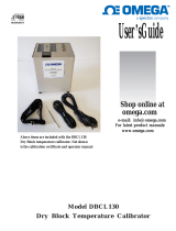
Shop online at
omega.com
e-mail: info@omega.com
For latest product manuals:
www.omega.com
Above items are included with the DBCL400
Dry Block temperature calibrator. Not shown
is the calibration certificate and operator manual
Model DBCL400
Dry Block Temperature Calibrator

2 | P a g e
DBCL400 Dry Block Temperature Calibrator
Introduction
The DBCL400 calibrator provides a safe, dry, constant temperature source for checking and calibrating a wide
range of temperature sensors, systems, indicators and thermometers. It is fast and economical and can be used
either on a bench top or as a portable field unit. The weight of the unit is only 11 pounds/5 kilograms. The unit
covers the temperature range from 5°C above ambient up to 450°C using a machined aluminum block as the
heat transfer medium. The temperature control circuit is built into the unit and includes over-temperature limit
protection.
Features include:
• Maximum temperature of 450°C/850°F
• An independent over-temperature cutout
Even though the unit heats up rapidly, highly efficient insulation and an internal cooling fan ensures that the
case remains cool enough to handle even at maximum operating temperatures. The DBCL400 calibrator has
been designed to comply with all relevant electromagnetic interference and electrical safety regulations.
Specification
11 lbs (5 Kg)
Dimensions* (H x W x D): 8.75 x 8 x 8 inches/222.25 x 203.2 x 203.2 mm
*excluding the carrying strap
Electrical supply
Voltage Cycles Power
230V 50/60Hz 900W
120V 50/60Hz 900W
Note:
The above specifications are quoted for an ambient temperature range of 10°C/50°F to 30°C/86°F.
Outside this range, the quoted figures may deteriorate but the unit will still work safely.
Working environment
The calibrator units are designed to work safely under the following conditions:
Ambient temperature range: 5°C/9°F to 40°C/104°F
Humidity: Up to 95% relative humidity, non-condensing
Figures quoted are at the base of the well at the time of calibration.
Temperature range: 5°C/9°F above ambient to 450°C/850°F
Over-temperature limit: 470°C/875°F
Display resolution: 0.1°
Accuracy: ±0.4°C (50 to 400°C) ±0.7°F (122 to 752°F)
±0.7°C (400 to 450°C) ±1.3°F (752 to 850°F)
Stability (after 15 minutes): ±0.050°C (50 to 400°C)
±0.090°F (122 to 752°F)
Well to well radial uniformity: 0.020°C at 200°C & 0.030°C at 400°C
Heat up time 25° C to 400°C: 12 minutes
Cool down 400°C to 100°C: 20 minutes
Immersion Depth: 4.5" (114.3mm)
Fan Cooling: Automatic
Weight:

3 | P a g e
Warning
Warning: HIGH TEMPERATURES ARE DANGEROUS
HIGH TEMPERATURES ARE DANGEROUS: They can cause serious burns to operators and ignite
combustible material. Accurate Thermal Systems has taken great care in the design of these units to
protect operators from hazards, but operators should pay attention to the following points:
• USE CARE AND WEAR PROTECTIVE GLOVES TO PROTECT HANDS
• DO NOT put hot objects on or near combustible objects
• DO NOT operate the unit close to inflammable liquids or gases
• DO NOT place any liquid directly in your unit
• At all times USE COMMON SENSE
Operator Safety
All operators of Omega Engineering equipment must have available the relevant literature needed to ensure
their safety. It is important that only suitably trained personnel operate this equipment in accordance with the
instructions contained in this manual and with general safety standards and procedures. If the equipment is
used in a manner not specified by Omega Engineering, the protection provided by the equipment to the
operator may be impaired. All Omega Engineering units have been designed to conform to international safety
requirements and are fitted with a self-resetting over-temperature cutout. If a safety problem is encountered,
switch off at the power socket and remove the plug from the supply. Please use caution when removing probes
and inserts as burns to the skin can occur if in contact.
Installation
1. All Omega Engineering units are supplied with a power cable.
2. Before connecting the power supply, check the voltage against the rating plate. Connect the power
cable to a suitable plug according to the table below. Note that the unit must be earth grounded to
ensure proper electrical safety.
Electrical
connections:
220V-240V
110V-120V
Live
Brown
Black
Neutral
Blue
White
Earth ground
Green/yellow
Green
The fused plug supplied with the power lead for use in the UK is fitted with the following value fuse
to protect the cable: 230V UK 4 AMP. The fuse in the unit protects the unit and the operator. Note that
units marked 230V on the rating plate work at 220V; units marked 120V work at 110V. In both cases,
however, the heating rate will degrade by approximately 8%. The rating plate is on the rear of the unit.
3. Plug the power cable into the socket on the rear of the unit.
4. Place the unit on a suitable bench or flat workspace, or in a fume cupboard if required, ensuring that
the air inlet vents on the underside are free from obstruction.
After use, when you have finished calibrating devices, remember that the insert and your
probe/thermometer may be very hot. Take the precautions listed earlier.

4 | P a g e
OPERATION
Preparation
1. The heater design, temperature sensor and control circuit give good temperature control and
uniformity, but make sure that there is a close fit of the probes in the block to allow efficient heat
transfer. Contact us about an insert that more closely fits your probe or device being calibrated.
2. Plug the power cable into the socket in the back of the unit. Connect the power cable to the
electrical supply and switch the power on. 1 = power on, 0 = power off.
3. Clean the heater block cavity out with
shop or canned air to remove any
particulate. Next place the probe insert
into the heater block as shown using the
supplied insert extractor to minimize the
risk of damaging the heater block and/or
probe insert. Never place a hot insert into
a cold heater block or vice versa as the
insert may become jammed which will
damage both parts. Always use the insert
extractor to both install and remove the
probe insert.
4. To prevent damage to the heater block,
insert, heaters and PRT block sensor DO
NOT use the following in or around the
block;
Oil, Thermal grease, Water
Aluminum oxide sand,
Ceramic fiber insulation or Kaowool
Setting the operating temperature
1. To set the operating temperature required, press and hold either the up or down arrow button to
increment to the value required. Alternatively you can press the key to move over to
individual digits to set higher values much quicker. Press to accept the set value.
2. When you have the correct set temperature displayed the unit will start to heat or cool to that
value.
3. Once the process value/actual temperature reaches the set point, allow the block to fully stabilize
for at least 15 minutes before performing a calibration.
4. Upon completion of your work set the temperature to 50°C/122°F or less and allow it to cool before
transporting or moving. The block fan will kick on to provide cooling. After a safe temperature has
been reached power can be switched off and the unit unplugged.
Display lockout
To prevent accidental changes to the calibration and temperature scale settings the display has been locked out
which is indicated by the key symbol in the display. To unlock the display press the down arrow and key at
the same time. The top line will show KEYP, press the up arrow so all values are zero then press and the
display will unlock. To relock the display press and then set the LOC parameter to LOC2. Press to save
and exit.

5 | P a g e
C to F temperature scale conversion
To change the temperature scale press to display parameter P0. Set this value to 11.0 for °C and 22.0 for
°F operation. Next press until parameter TPUN is displayed and set to C or F. Then change TP-H to
450(°C) or 850(°F). Do not set Tp-H any higher than the values shown or damage may occur. Press to
display parameter PVOF. This calibration value must be changed to maintain calibrated accuracy. The default
factory value is shown below. When switching from F to C divide the value by 1.8 and enter into PVOF and
multiply by 1.8 for conversion from C to F. Calibration adjustments are discussed below.
Calibration
The unit has been calibrated by the factory to meet specifications. In the event that you want to adjust or
correct the calibration use the following parameters with the display unlocked.
Press and PVOF will display which is the Zero or low end adjustment. Enter a negative value to correct for
low readings and vice versa. For example if your reference thermometer is showing that the ThermCal400 is 2.0
degrees low then enter a -2.0. Press to access PV6A which is the span or high end correction. Use a
negative value for readings that are low. In most cases you will only need to adjust PVOF to correct for any
errors.
The factory calibration values for unit S/N: are PVOF = PV6A = °C
Operator maintenance
NOTE THAT THIS EQUIPMENT SHOULD ONLY BE DISMANTLED BY PROPERLY TRAINED PERSONNEL.
REMOVING THE FRONT OR REAR PANELS EXPOSES POTENTIALLY LETHAL VOLTAGES. THERE ARE NO
OPERATOR MAINTAINABLE PARTS WITHIN THE EQUIPMENT
.
In the unlikely event that you experience any problems with your unit which cannot easily be remedied, you
should contact your supplier and return the unit if necessary. Please include any details of the fault observed
and remember to return the unit in its original packing. Omega Engineering will accept no responsibility for any
damage to units that are improperly packed for shipment. If in doubt, contact your supplier.
1.
Cleaning: Before cleaning your unit, ALWAYS disconnect it from the power supply and allow it to
cool below 50° C. Your unit can be cleaned by wiping with a damp soapy cloth. Care should be
exercised to prevent water from running inside the unit. Do not use abrasive cleaners.
2.
Fuse: The unit is protected by a fuse. It should only be changed by suitably qualified
personnel. If the fuse blows persistently, a serious fault is indicated and you may need to return the
unit to your supplier for repair.

6 | P a g e
Accessories
The following parts may be obtained directly from Omega Engineering
Part Number Description
4163 UK 240 volt power cable with 13amp UK plug (5 amp fuse)
4164 Euro style 240 volt power cable with R/A Schuko plug
4150 US style 120 volt power cable
4168 Unit carrying strap
4153 Insert extractor
DBCL-400-3041 Multiwell insert 1/8, 3/16, ¼, 5/16 & 3/8” holes
DBCL-400-3047 Blank insert
DBCL-400-3043 Insert 5 x 1/4" holes
DBCL-400-3048 Insert 1 x 9/16" & 1 x 1/4" holes
DBCL-400-3044 Insert 2 x 1/4" & 2 x 3/8" holes
DBCL-400-3049 Insert 1 x 5/8" & 1 x 1/4" holes
DBCL-400-3045 Insert 2 x 1/4" & 2 x 1/2" holes
DBCL-400-3050 Insert 1 x 11/16" & 1 x 1/4" holes
DBCL-400-3046 Insert 1 x 1/4" hole
DBCL-400-3051 Insert 1 x 3/4" & 1 x 1/4" holes
DBCL-3052 Carrying case
Spare Parts
Part Number Description
4146 225 watt, 120 volt heater
4317 Temperature controller
4147 PRT
4145 Solid state relay
4165 4 amp fuse (240 volt units)
4157 8 amp fuse (120 volt units)
AD66 Heater block
4148 120 volt block cooling fan
4162 240 volt block cooling fan
4170 120 volt chassis cooling fan
4171 240 volt chassis cooling fan

7 | P a g e
EU Declaration of Conformity (No. DC18-DBCL)
In accordance with European Parliament and Council Decision No 768/2008/EC Annex III
1. Product model / product:
Product Dry Block Temperature Calibrator
Model/type DBCL400 & DBCL130
Batch/serial no. S/N: 619-2993 & onward
2.Manufacturer
Name Omega Engineering
Address 800 Connecticut Ave, Norwalk, CT 06854
3. This declaration is issued under the sole responsibility of the manufacturer.
4. Object of the declaration:
Product Dry Block Temperature Calibrator
Specification Model DBCL400 operating range ambient +5 to 450°C
Model DBCL130 operating range -25 to 130°C (20°C ambient)
5. The object of the declaration described above is in conformity with the relevant Union
harmonisation legislation:
2014/35/EU The Low Voltage Directive
2014/30/EU The Electromagnetic Compatibility Directive
2011/65/EU The Restriction of Hazardous Substances Directive
6. References to the relevant harmonised standards used or references to the other technical
specifications in relation to which conformity is declared:
Reference & Date
Title
EN 60519-1:2015
Safety in installations for electroheating and electromagnetic
processing. General requirements
EN 61000-6-2:2005
Electromagnetic compatibility (EMC) - Part 6-2: Generic standards
- Immunity for industrial environments
EN 61000-6-4:2007 +
A1:2011
Electromagnetic compatibility (EMC) - Part 6-4: Generic standards
- Emission standard for industrial environments
EN 50581:2012
Technical documentation for the assessment of electrical and
electronic products with respect to the restriction of hazardous
substances
7. Additional information:
Signed for and on behalf of: Omega Engineering
Place of issue: Hainesport, NJ, USA
Date of issue: July 8, 2019
Name: Darren Sager
Signature:
Darren Sager
Rev 5 8/19

omega.com
info@omega.com
Servicing North America:
U.S.A
.
Omega Engineering, Inc.
Headquarters:
Toll-Free: 1-800-826-6342 (USA & Canada only)
Customer Service: 1-800-622-2378 (USA & Canada only)
Engineering Service: 1-800-872-9436 (USA & Canada only)
Tel: (203) 359-1660 Fax: (203) 359-7700
e-mail: [email protected]
For Other Locations Visit omega.com/worldwide
The information contained in this document is believed to be correct, but OMEGA accepts no liability for any errors it contains, and reserves
the right to alter specifications without notice.

OMEGA’s policy is to make running changes, not model changes, whenever an improvement is possible. This affords
our customers the latest in technology and engineering.
OMEGA is a registered trademark of OMEGA ENGINEERING, INC.
© Copyright 2016 OMEGA ENGINEERING, INC. All rights reserved. This document may not be copied, photocopied,
reproduced, translated, or reduced to any electronic medium or machine-readable form, in whole or in part, without the
prior written consent of OMEGA ENGINEERING, INC.
FOR WARRANTY RETURNS, please have the
following information available BEFORE contacting
OMEGA:
1. Purchase Order number under which the product
was PURCHASED,
2. Model and serial number of the product under
warranty, and
3. Repair instructions and/or specific problems
relative to the product.
FOR NON-WARRANTY REPAIRS,
consult
OMEGA for current repair charges. Have
the following information available BEFORE
contacting OMEGA:
1. Purchase Order number to cover the COST
of the repair,
2. Model and serial number of the product, and
3. Repair instructions and/or specific problems
relative to the product.
RETURN REQUESTS/INQUIRIES
Direct all warranty and repair requests/inquiries to the OMEGA Customer Service Department.
BEFORE RETURNING ANY PRODUCT(S) TO OMEGA, PURCHASER MUST OBTAIN AN AUTHORIZED
RETURN (AR) NUMBER FROM OMEGA’S CUSTOMER SERVICE DEPARTMENT (IN ORDER TO AVOID
PROCESSING DELAYS). The assigned AR number should then be marked on the outside of the return
package and on any correspondence.
The purchaser is responsible for shipping charges, freight, insurance and proper packaging to prevent
breakage in transit.
WARRANTY/DISCLAIMER
OMEGA ENGINEERING, INC. warrants this unit to be free of defects in materials and workmanship for a
period of 13 months from date of purchase. OMEGA’s WARRANTY adds an additional one (1) month
grace period to the normal one (1) year product warranty to cover handling and shipping time. This
ensures that OMEGA’s customers receive maximum coverage on each product.
If the unit malfunctions, it must be returned to the factory for evaluation. OMEGA’s Customer Service
Department will issue an Authorized Return (AR) number immediately upon phone or written request.
Upon examination by OMEGA, if the unit is found to be defective, it will be repaired or replaced at no
charge. OMEGA’s WARRANTY does not apply to defects resulting from any action of the purchaser,
including but not limited to mishandling, improper interfacing, operation outside of design limits,
improper repair, or unauthorized modification. This WARRANTY is VOID if the unit shows evidence of
having been tampered with or shows evidence of having been damaged as a result of excessive corrosion;
or current, heat, moisture or vibration; improper specification; misapplication; misuse or other operating
conditions outside of OMEGA’s control. Components in which wear is not warranted, include but are not
limited to contact points, fuses, and triacs.
OMEGA is pleased to offer suggestions on the use of its various products. However,
OMEGA neither assumes responsibility for any omissions or errors nor assumes liability for
any damages that result from the use of its products in accordance with information provided
by OMEGA, either verbal or written. OMEGA warrants only that the parts manufactured by the
company will be as specified and free of defects. OMEGA MAKES NO OTHER WARRANTIES OR
REPRESENTATIONS OF ANY KIND WHATSOEVER, EXPRESSED OR IMPLIED, EXCEPT THAT OF
TITLE, AND ALL IMPLIED WARRANTIES INCLUDING ANY WARRANTY OF MERCHANTABILITY
AND FITNESS FOR A PARTICULAR PURPOSE ARE HEREBY DISCLAIMED. LIMITATION OF
LIABILITY: The remedies of purchaser set forth herein are exclusive, and the total liability of
OMEGA with respect to this order, whether based on contract, warranty, negligence,
indemnification, strict liability or otherwise, shall not exceed the purchase price of the
component upon which liability is based. In no event shall OMEGA be liable for
consequential, incidental or special damages.
CONDITIONS: Equipment sold by OMEGA is not intended to be used, nor shall it be used: (1) as a “Basic
Component” under 10 CFR 21 (NRC), used in or with any nuclear installation or activity; or (2) in medical
applications or used on humans. Should any Product(s) be used in or with any nuclear installation or
activity, medical application, used on humans, or misused in any way, OMEGA assumes no responsibility
as set forth in our basic WARRANTY/DISCLAIMER language, and, additionally, purchaser will indemnify
OMEGA and hold OMEGA harmless from any liability or damage whatsoever arising out of the use of the
Product(s) in such a manner.

M0000/0019
Where Do I Find Everything I Need for
Process Measurement and Control?
OMEGA…Of Course!
Shop online at omega.com
TEMPERATURE
MU
Thermocouple, RTD & Thermistor Probes, Connectors, Panels & Assemblies
MU
Wire: Thermocouple, RTD & Thermistor
MU
Calibrators & Ice Point References
MU
Recorders, Controllers & Process Monitors
MU
Infrared Pyrometers
PRESSURE, STRAIN AND FORCE
MU
Transducers & Strain Gages
MU
Load Cells & Pressure Gages
MU
Displacement Transducers
MU
Instrumentation & Accessories
FLOW/LEVEL
MU
Rotameters, Gas Mass Flowmeters & Flow Computers
MU
Air Velocity Indicators
MU
Turbine/Paddlewheel Systems
MU
Totalizers & Batch Controllers
pH/CONDUCTIVITY
MU
pH Electrodes, Testers & Accessories
MU
Benchtop/Laboratory Meters
MU
Controllers, Calibrators, Simulators & Pumps
MU
Industrial pH & Conductivity Equipment
DATA ACQUISITION
MU
Communications-Based Acquisition Systems
MU
Data Logging Systems
MU
Wireless Sensors, Transmitters, & Receivers
MU
Signal Conditioners
MU
Data Acquisition Software
HEATERS
MU
Heating Cable
MU
Cartridge & Strip Heaters
MU
Immersion & Band Heaters
MU
Flexible Heaters
MU
Laboratory Heaters
ENVIRONMENTAL
MONITORING AND CONTROL
MU
Metering & Control Instrumentation
MU
Refractometers
MU
Pumps & Tubing
MU
Air, Soil & Water Monitors
MU
Industrial Water & Wastewater Treatment
MU
pH, Conductivity & Dissolved Oxygen Instruments
-
 1
1
-
 2
2
-
 3
3
-
 4
4
-
 5
5
-
 6
6
-
 7
7
-
 8
8
-
 9
9
-
 10
10


Omega DBCL400, your new temperature calibrator, provides accurate and stable temperature control for calibrating a wide range of temperature sensors, systems, and thermometers. Its key features include:
- Wide temperature range from 5°C above ambient to 450°C, covering most industrial applications
- Precise temperature control, with accuracy of ±0.4°C and stability of ±0.
Ask a question and I''ll find the answer in the document
Finding information in a document is now easier with AI
Related papers
-
Omega DBCL400 User guide
-
 Spectris Omega DBCL130 User manual
-
Omega GCW Series Owner's manual
-
-
-
-
-
-
-