Page is loading ...

THE HIGH PERFORMANCE COMPANY
SERIES 3W/3L
RESILIENT SEATED BUTTERFLY VALVES
INSTALLATION, OPERATION AND MAINTENANCE MANUAL
BRAY.COM

SERIES 3W/3L RESILIENT SEATED BUTTERFLY VALVES
Installation, Operation and Maintenance Manual
© 2021 BRAY INTERNATIONAL, INC. ALL RIGHTS RESERVED. BRAY.COM
The Information contained herein shall not be copied, transferred, conveyed, or displayed in any manner
that would violate its proprietary nature without the express written permission of Bray International, Inc.
2 of 22
CONTENTS
1.0 Definition of Terms . . . . . . . . . . . . . . . . . . . . . . . . . . . . . . . . . . . . . . . . . . . 3
2.0 Introduction . . . . . . . . . . . . . . . . . . . . . . . . . . . . . . . . . . . . . . . . . . . . . . . 4
3.0 Shipment and Storage . . . . . . . . . . . . . . . . . . . . . . . . . . . . . . . . . . . . . . . . . 5
4.0 Installation Considerations, Piping and Valve Orientation and Placement . . . . . . . . . . . . 6
4.1 Piping and Flanged Compatibilities ................................................6
4.2 Valves with Spring Return Actuators...............................................6
4.3 Valve Location ..................................................................7
4.4 Valve Orientation ................................................................8
5.0 Installation Procedure. . . . . . . . . . . . . . . . . . . . . . . . . . . . . . . . . . . . . . . . . .12
5.1 General Installation .............................................................12
6.0 Maintenance and Repair . . . . . . . . . . . . . . . . . . . . . . . . . . . . . . . . . . . . . . . .16
7.0 Disassembly/Assembly Instructions NPS 2-20 (DN50-500). . . . . . . . . . . . . . . . . . . .17
7.1 Disassembly ...................................................................17
7.2 Assembly ......................................................................17
8.0
Disassembly/Assembly Instructions NPS 24 (DN600) . . . . . . . . . . . . . . . . . . . . . . . . 19
8.1 Disassembly ...................................................................19
8.2 Assembly ..................................................................... 20
For information on this product and other Bray products please visit us at our web page - www.bray.com

SERIES 3W/3L RESILIENT SEATED BUTTERFLY VALVES
Installation, Operation and Maintenance Manual
© 2021 BRAY INTERNATIONAL, INC. ALL RIGHTS RESERVED. BRAY.COM
The Information contained herein shall not be copied, transferred, conveyed, or displayed in any manner
that would violate its proprietary nature without the express written permission of Bray International, Inc.
3 of 22
READ AND FOLLOW THESE INSTRUCTIONS CAREFULLY.
SAVE THIS MANUAL FOR LATER USE.
1.0 DEFINITION OF TERMS
WARNING
Indicates a potentially hazardous situation which, if not avoided, could
result in death or serious injury.
CAUTION
Indicates a potentially hazardous situation which, if not avoided, may
result in minor or moderate injury.
NOTICE
Used without the safety alert symbol, indicates a potential situation
which, if not avoided, may result in an undesirable result or state,
including property damage.

SERIES 3W/3L RESILIENT SEATED BUTTERFLY VALVES
Installation, Operation and Maintenance Manual
© 2021 BRAY INTERNATIONAL, INC. ALL RIGHTS RESERVED. BRAY.COM
The Information contained herein shall not be copied, transferred, conveyed, or displayed in any manner
that would violate its proprietary nature without the express written permission of Bray International, Inc.
4 of 22
2.0 INTRODUCTION
Historical Experience
Based on over thirty years experience in the butterfly valve
industry, Bray can state without question the majority of all field problems
for resilient seated butterfly valves are directly related to poor installation
procedures. For this reason, it is very important all distributors educate
their customers regarding proper installation of resilient seated butterfly
valves.
Butterfly Valve Seat / Disc Function
Before reviewing the proper installation, maintenance, and repair
procedures for resilient seated butterfly valves, let’s discuss the seat-disc
function of a butterfly valve. The seat in a resilient seated butterfly valve
has a molded tear drop profile on its flange face. As a result, no gaskets
are required as this profile serves the function of a gasket. The flange
face and molded profile of the seat extend beyond the body face-to-face
to ensure sealing at the flange faces.
The seat inside diameter (I.D.) of all resilient seated butterfly valves is
smaller than the disc outside diameter (O.D.) This dierence, the disc-seat
interference, has been engineered so as to be the basis for pressure rating
capability and the related seating/unseating torques.
Finally, unlike many valve types, the resilient seated
butterfly valve’s disc actually extends beyond the face of the valve body
at given angles of opening (say, 30° or more) when installed between
flanges.
CAUTION
It is very important before installation to ensure the critical chordal dimension of
the disc at the full open position is less than the adjacent pipe flange I.D. (Refer
to Series 3W/3L Technical Manual for chordal dimensions).

SERIES 3W/3L RESILIENT SEATED BUTTERFLY VALVES
Installation, Operation and Maintenance Manual
© 2021 BRAY INTERNATIONAL, INC. ALL RIGHTS RESERVED. BRAY.COM
The Information contained herein shall not be copied, transferred, conveyed, or displayed in any manner
that would violate its proprietary nature without the express written permission of Bray International, Inc.
5 of 22
3.0 SHIPMENT AND STORAGE
1. The seat, disc, stem and bushing of the resilient seated butterfly
valve should be coated with silicone lubricant unless specified
otherwise.
2. The disc should be positioned at 10° open.
Note: See page 6 for special considerations for valves with spring
return actuators.
3. Valves should be stored indoors with a preferred temperature range
from 40°F (4°C) to 85°F (29°C).
4. When valves are in storage, they should be opened and closed once
every 3 months.
5. Ship and store valves so that no heavy loads are applied to the
bodies
6. Polymer and elastomer parts should not be stored in the presence of
sunlight or artificial light with high ultraviolet content, or any source
of radiation as these are primary causes of aging.
7. If a component is cooled below 59°F (15°C), the entire valve
assembly should be allowed to rise above 68°F (20°C) before
installing into service.
8. Valve end protectors should only be removed at the time of valve
installation.

SERIES 3W/3L RESILIENT SEATED BUTTERFLY VALVES
Installation, Operation and Maintenance Manual
© 2021 BRAY INTERNATIONAL, INC. ALL RIGHTS RESERVED. BRAY.COM
The Information contained herein shall not be copied, transferred, conveyed, or displayed in any manner
that would violate its proprietary nature without the express written permission of Bray International, Inc.
6 of 22
4.0 INSTALLATION CONSIDERATIONS, PIPING AND VALVE
ORIENTATION AND PLACEMENT
4.1 Piping and Flanged Compatibilities
4.1.1 Piping
These valves have been engineered so that the critical disc chordal
dimension at the full open position will clear the adjacent inside diameter
of most types of piping, including Schedule 40, lined pipe, heavy wall, etc.
4.1.2 Metal Flanges
Bray’s resilient seated butterfly valves have been designed to be suitable
for all types of flanges (ASME, DIN, JIS and other international flange
standards), whether flat-faced, raised face, slip-on, weld-neck, etc. Proper
alignment of any butterfly valve between flanges is critical to good
performance of the valve. The flange bolts must also be evenly tightened
around the circumference of the valve, providing consistent flange
compression of the molded profile on the seat face.
Since Bray does not recommend the use of gaskets between flanges on
resilient seated butterfly valves, a uniform flange face is critical to proper
valve sealing. Most weld-neck and slip-on flanges conforming to ASME
specifications have an appropriate flange face. Type A and B butt-weld
stub-end flanges also provide a suitable mating surface for the molded
tear drop profile on the flange face.”
It should be noted that Type C butt-weld stub-end flanges have an “as
formed” flange face. The varying surface of this flange face can create
sealing problems between any resilient-seated butterfly valve and the
flange face. For this reason, Type C flanges are not recommended for use
with resilient-seating butterfly valves.
4.1.3 Non-Metallic Flanges
When non-metallic flanges, such as plastic or PVC, are used with resilient
seated butterfly valves, care must be taken not to over-tighten the flange
bolts. The inherent flexibility of these non-metallic flange materials allow
them to be over-tightened relatively easily. Flexing caused by this over-
tightening can actually reduce the compression of the valve between
the flanges, causing leaks between the valve and the flange face. Proper
alignment and firm, even, but not excessive tightening of flange bolts
are especially important with non-metallic flanges. In some cases, non-
metallic flanges of low quality will not mate tightly with butterfly valves
regardless of the care taken during installation.
4.2 Valves with Spring Return Actuators
4.2.1 Fail Closed Assemblies
If the valve is supplied with an actuator, the butterfly valve is shipped
in the full closed position (as no air pressure is present to compress the
springs and open the disc).
4.2.2 Fail Open Assemblies
If the valve is supplied with an actuator, the butterfly valve disc is shipped
in the full open position (as no air pressure is present to compress the
springs and close the valve disc.) The sealing surface, or disc edge, is
therefore exposed. Damage to that surface will cause premature seat
failure.

SERIES 3W/3L RESILIENT SEATED BUTTERFLY VALVES
Installation, Operation and Maintenance Manual
© 2021 BRAY INTERNATIONAL, INC. ALL RIGHTS RESERVED. BRAY.COM
The Information contained herein shall not be copied, transferred, conveyed, or displayed in any manner
that would violate its proprietary nature without the express written permission of Bray International, Inc.
7 of 22
CAUTION
Use caution installing the valve being careful not to damage the disc edge. It is
recommended to:
> Remove the actuator. Be sure to scribe the valve and actuator to ensure the
re-installed actuator is in the exact same quadrant as originally configured
> Install the valve per the attached installation tag instructions
> Re-install the actuator ensuring it is in the proper quadrant
4.3 Valve Location
1. Resilient seated butterfly valves should be installed if possible a
minimum of 6 pipe diameters from other line elements, i.e., elbows,
pumps, valves, etc. of course, 6 pipe diameters are not always
practical, but it is important to achieve as much distance as possible.
2. Where the resilient seated butterfly valve is connected to a check
valve or pump, use an expansion joint between them to ensure the
disc does not interfere with the adjacent equipment.

SERIES 3W/3L RESILIENT SEATED BUTTERFLY VALVES
Installation, Operation and Maintenance Manual
© 2021 BRAY INTERNATIONAL, INC. ALL RIGHTS RESERVED. BRAY.COM
The Information contained herein shall not be copied, transferred, conveyed, or displayed in any manner
that would violate its proprietary nature without the express written permission of Bray International, Inc.
8 of 22
4.4 Valve Orientation
1. In general, Bray recommends the resilient seated valve be installed
with the stem in the vertical position and the actuator mounted
directly above the valve; however, there are those applications as
discussed below where the stem should be horizontal. NOTE: Bray
does not recommend valves be installed in an upside-down position.
2. For slurries, sludge, mine tailing, pulp stock, dry cement, and any
media with sediment or particles, Bray recommends the resilient
seated valve be installed with the stem in the horizontal position
with the lower disc edge opening in the downstream direction as
illustrated below.
FLOW
Stem (Vertical)
INCORRECT INSTALLATION
Sludge builds up on disc
FLOW
Stem (Horizontal)
CORRECT INSTALLATION
Sludge passes under disc

SERIES 3W/3L RESILIENT SEATED BUTTERFLY VALVES
Installation, Operation and Maintenance Manual
© 2021 BRAY INTERNATIONAL, INC. ALL RIGHTS RESERVED. BRAY.COM
The Information contained herein shall not be copied, transferred, conveyed, or displayed in any manner
that would violate its proprietary nature without the express written permission of Bray International, Inc.
9 of 22
4.4 Valve Orientation (Continued)
Resilient seated butterfly valve, located at the discharge of a pump should be oriented as follows:
2 Centrifugal Pump –
Pump shaft vertical
and stem horizontal
1. Centrifugal Pump –
Pump shaft horizontal
and stem vertical
3. Axial Pump –
Pump shaft vertical
and stem vertical
INCORRECT INSTALLATION CORRECT INSTALLATION
Pump Shaft
(Horizontal)
Pump Shaft
(Horizontal)
Stem
(Horizontal)
Stem
(Vertical)
FLOW FLOW
Pump Shaft
(Vertical)
Pump Shaft
(Vertical)
FLOW FLOW
Stem
(Horizontal)
Stem
(Vertical)
Suction Suction
Pump Shaft
(Vertical)
Pump Shaft
(Vertical)
FLOW FLOW
Suction Suction
Stem
(Horizontal)
Stem
(Vertical)

SERIES 3W/3L RESILIENT SEATED BUTTERFLY VALVES
Installation, Operation and Maintenance Manual
© 2021 BRAY INTERNATIONAL, INC. ALL RIGHTS RESERVED. BRAY.COM
The Information contained herein shall not be copied, transferred, conveyed, or displayed in any manner
that would violate its proprietary nature without the express written permission of Bray International, Inc.
10 of 22
4.4 Valve Orientation (Continued)
Butterfly valves located downstream of a bend or pipe reducer should be oriented as follows:
2. Tee
1. Bend
3. Pipe Reducer
INCORRECT INSTALLATION CORRECT INSTALLATION
Stem
(Horizontal)
Stem
(Vertical)
FLOW
FLOW
FLOW
FLOW FLOW
FLOW
Stem
(Horizontal)
Stem
(Horizontal)
Stem
(Vertical)
Stem
(Vertical)

SERIES 3W/3L RESILIENT SEATED BUTTERFLY VALVES
Installation, Operation and Maintenance Manual
© 2021 BRAY INTERNATIONAL, INC. ALL RIGHTS RESERVED. BRAY.COM
The Information contained herein shall not be copied, transferred, conveyed, or displayed in any manner
that would violate its proprietary nature without the express written permission of Bray International, Inc.
11 of 22
Combination with all valve stems in the same direction
accelerates possible noise, vibration, & erosion problems.
Combination with the stem of the control valve at right angle
to those of other valves tends to cancel the drift of the fluid,
and reduces noises, vibration, and erosion.
4.4 Valve Orientation (Continued)
Butterfly valves in combination for control/isolation applications should be installed as follows:
INCORRECT INSTALLATION CORRECT INSTALLATION
FLOW FLOW

SERIES 3W/3L RESILIENT SEATED BUTTERFLY VALVES
Installation, Operation and Maintenance Manual
© 2021 BRAY INTERNATIONAL, INC. ALL RIGHTS RESERVED. BRAY.COM
The Information contained herein shall not be copied, transferred, conveyed, or displayed in any manner
that would violate its proprietary nature without the express written permission of Bray International, Inc.
12 of 22
5.0 INSTALLATION PROCEDURE
5.1 General Installation
1. Make sure the pipeline and pipe flange faces are clean. Any foreign
material such as pipe scale, metal chips, welding slag, welding rods,
etc., can obstruct disc movement or damage the disc or seat.
2. The Bray elastomer seat has a molded tear drop profile on the face
of the seat. As a result, no gaskets are required as this profile serves
the function of a gasket.
3. Align the piping and then spread the pipe flanges a distance apart
so as to permit the valve body to be easily dropped between the
flanges without contacting the pipe flanges (see Figure 1 page 13).
4. Check to see that the valve disc has been positioned to a partially
open position, with the disc edge about 1/2 inch to 3/8 inch inside
the face of the seat, (approximately 10° open) (see Figure 1 page 13)
Note: See page 6 for special consideration for valves with spring
return actuators.
5. Insert the valve between the flanges as shown in Figure 1 on page
13, taking care not to damage the seat faces. Always pick the valve
up by the locating holes or by using a nylon sling on the neck of the
body.
WARNING
Never pick up the valve by the actuator or operator mounted on top of the valve.
6. Place the valve between the flanges, center it, and then span
the valve body with all flange bolts, but do not tighten the bolts.
Carefully open the disc to the full open position, making sure the
disc does not hit the adjacent pipe I.D. Now systematically remove
jack bolts or other flange spreaders, and hand-tighten the flange
bolts as shown in Figure 2 (page 13). Very slowly close the valve
disc to ensure disc edge clearance from the adjacent pipe flange
I.D. Now open the disc to full open and tighten all flange bolts per
specification as shown in Figure 2 (page 13). Finally, repeat a full
close to full open rotation of the disc to ensure proper clearances
(See Figures 3 & 4 page 14).
7. For additional flange bolting information please reference the
Series 3W/3L Technical Sales Manual found at www.bray.com.

SERIES 3W/3L RESILIENT SEATED BUTTERFLY VALVES
Installation, Operation and Maintenance Manual
© 2021 BRAY INTERNATIONAL, INC. ALL RIGHTS RESERVED. BRAY.COM
The Information contained herein shall not be copied, transferred, conveyed, or displayed in any manner
that would violate its proprietary nature without the express written permission of Bray International, Inc.
13 of 22
INCORRECT INSTALLATION CORRECT INSTALLATION
Figure 1 – Insert Resilient Seated Butterfly Valve Between Flanges
Pipe spread and aligned, disc rotated;
Results: No undesirable beginning seating/unseating torque,
disc edge protected.
Figure 2 – Flange Bolt Tightening Pattern
Pipe not spread, disc opened beyond valve body face;
Results: Disc edge damaged when it hits pipe flange.
1
5
3
8
2 6
4
7

SERIES 3W/3L RESILIENT SEATED BUTTERFLY VALVES
Installation, Operation and Maintenance Manual
© 2021 BRAY INTERNATIONAL, INC. ALL RIGHTS RESERVED. BRAY.COM
The Information contained herein shall not be copied, transferred, conveyed, or displayed in any manner
that would violate its proprietary nature without the express written permission of Bray International, Inc.
14 of 22
INCORRECT INSTALLATION CORRECT INSTALLATION
Figure 3 – Initial Centering & Flanging of Valve
Nuts snugged, not torqued tight, disc edge within body face-
to-face but not fully closed, no flange gaskets;
Results: No disc edge damage, proper sealing allowed.
Figure 4 – Final Aligning & Tightening of Flange Bolts
Piping misaligned;
Results: Disc O.D. strikes pipe I.D. causing disc edge damage,
increased torque & leakage. Seat face o-rings will not seal
properly with incorrectly aligned piping.
Piping aligned properly when bolts tightened, disc in full
open position;
Results: Disc clears adjacent pipe I.D., seat face seals
properly, no excessive initial torque.
Disc in closed position; gaskets used;
Results: Seat distorted and over-compressed causing
high initial unseating torque problems.
INCORRECT INSTALLATION CORRECT INSTALLATION

SERIES 3W/3L RESILIENT SEATED BUTTERFLY VALVES
Installation, Operation and Maintenance Manual
© 2021 BRAY INTERNATIONAL, INC. ALL RIGHTS RESERVED. BRAY.COM
The Information contained herein shall not be copied, transferred, conveyed, or displayed in any manner
that would violate its proprietary nature without the express written permission of Bray International, Inc.
15 of 22
When resilient seated butterfly valves are to be installed between welding
type flanges, care should be taken to abide by the following procedure to
ensure no damage will occur to the seat:
1. Place the valve between the flanges with the flange bores and valve
body aligned properly. The disc should be in the 10° open position.
2. Span the body with the bolts.
3. Take this assembly of flange-body-flange and align it properly to the
pipe.
4. Tack weld the flanges to the pipe.
5. When tack welding is complete, remove the bolts and the valve from
the pipe flanges and complete the welding of the flanges. Be sure to
let the pipe and flanges cool before installing the valve.
CAUTION
Never complete the welding process (after tacking) with the valve between pipe
flanges. This causes severe seat damage due to heat transfer.

SERIES 3W/3L RESILIENT SEATED BUTTERFLY VALVES
Installation, Operation and Maintenance Manual
© 2021 BRAY INTERNATIONAL, INC. ALL RIGHTS RESERVED. BRAY.COM
The Information contained herein shall not be copied, transferred, conveyed, or displayed in any manner
that would violate its proprietary nature without the express written permission of Bray International, Inc.
16 of 22
6.0 MAINTENANCE AND REPAIR
No routine lubrication is required. All components – stem, disc, body/
seat, bushing, stem seal, etc., are field replaceable, no adjustment is
required. If components require replacement, the valve must be removed
from the line by placing the disc in the near closed position, then
supporting the valve and removing the flange bolts.
WARNING
No valve maintenance, including removal of manual or power actuators, should
be performed until the piping system is completely depressurized.

SERIES 3W/3L RESILIENT SEATED BUTTERFLY VALVES
Installation, Operation and Maintenance Manual
© 2021 BRAY INTERNATIONAL, INC. ALL RIGHTS RESERVED. BRAY.COM
The Information contained herein shall not be copied, transferred, conveyed, or displayed in any manner
that would violate its proprietary nature without the express written permission of Bray International, Inc.
17 of 22
7.0 DISASSEMBLY/ASSEMBLY INSTRUCTIONS NPS 2-20
(DN50-500)
Note: The molded-in seat and stem bearings are not removed from the
valve body during disassembly.
7.1 Disassembly
1. Remove the handle, gear operator, or power actuator from actuator
mounting flange.
2. Remove the Spirolox® retaining ring, the thrust washer and the two
C-ring stem retainers from the stem hole.
3. Then remove the stem, bushing and seal.
4. Remove the disc from the seat, protecting the disc edge at all times.
7.2 Assembly
1. Insert stem seal.
2. Push stem into the stem hole of the body until the bottom of the
stem is flush with the inner top edge of the seat.
3. Install a light coating of silicone or grease on the I.D. of seat. Insert
the disc into the seat by lining up the disc holes with the stem holes
of the seat.
Note: The broached double “D” flats in the disc must be toward the
bottom of the valve body.
4. With a downward pressure and rotating the stem back and forth,
push the stem until the stem touches the bottom of the body stem
hole.
NOTE: The Spirolox® retaining ring must be installed into the groove
cut into the stem hole I.D. in the body to perform it’s function
properly.
5. Replace handle, manual gear operator or power actuator
on the actuator mounting flange.

SERIES 3W/3L RESILIENT SEATED BUTTERFLY VALVES
Installation, Operation and Maintenance Manual
© 2021 BRAY INTERNATIONAL, INC. ALL RIGHTS RESERVED. BRAY.COM
The Information contained herein shall not be copied, transferred, conveyed, or displayed in any manner
that would violate its proprietary nature without the express written permission of Bray International, Inc.
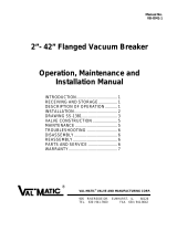
18 of 22
Disc
Body/Seat
Stem
Stem Seal
Stem Bushing
Retaining Ring
Thrust Washer
Stem Retainer
Series 3W - NPS 6 (DN 150)
Upper Stem Bearing
Lower Stem Bearing

SERIES 3W/3L RESILIENT SEATED BUTTERFLY VALVES
Installation, Operation and Maintenance Manual
© 2021 BRAY INTERNATIONAL, INC. ALL RIGHTS RESERVED. BRAY.COM
The Information contained herein shall not be copied, transferred, conveyed, or displayed in any manner
that would violate its proprietary nature without the express written permission of Bray International, Inc.
19 of 22
8.0
DISASSEMBLY/ASSEMBLY INSTRUCTIONS NPS 24 (DN 600)
8.1 Disassembly
1. Remove the gear operator or power actuator from the actuator
mounting flange.
2. Secure the valve in a horizontal position.
CAUTION
Prior to removal of the valve stems the valve disc must be secured and supported
to insure it does not drop out of the valve body once the stems are removed. Lay
the valve down with two wood blocks located under the disc at the 6 o’clock and
12 o’clock positions making sure the blocks are in close contact with the disc but
not supporting the valve.
3. Removal of the lower valve stem:
a. Remove the bottom plate screws, bottom plate, bottom plate
gasket and thrust bearing.
b. Remove the locking nut from the tie bolt
c. Remove the stem retainer..
d. Secure a hoist to the lower stem (end is imperial threaded).
e. Then use the hoist to remove the lower stem from the valve body.
f. Remove the stem bearing.
4. Removal of the upper valve stem:
a. Remove the packing gland by removing the retaining screws and
sliding the gland o the top of the stem.
b. Secure a hoist to the upper stem (end is imperial threaded).
c. Then use the hoist to remove the upper stem including the tie bolt
from the valve body.
5. Removal of the valve disc:
a. Remove the wood blocks noted above from below the disc.
b. Using a rubber hammer, pound one area of the disc (ex. 12 o’clock
position) repeatedly until the disc clears the face of the valve body.
6. Removal of packing and bearings:
a. Remove the stem packing.
b. Use a slotted screwdriver to carefully remove the upper and lower
stem bearings.
8.2 Assembly
1. Installation of the valve disc:
Note: Before installing the disc, check to assure the upper and lower
stems are matched to the upper and lower stem holes in the disc.
a. With the valve still in the vice in a vertical position, hoist the upper
stem with the splined end or the double keyed end pointing upward.
b. Push the upper stem into the stem hole of the upper body until the
bottom of the stem exceeds the upper stem hole of the seat by 20-
50 mm.
c. Apply a light coating of silicone or grease on the I.D. of the seat.
d. Insert the disc into the seat with the splined end or the double
keyed end up.
e. Push the disc into the seat while inserting the upper stem into the
upper stem hole in the disc.
f. Adjust the disc to assure the lower stem hole of the disc is properly
aligned with the lower body stem hole.

SERIES 3W/3L RESILIENT SEATED BUTTERFLY VALVES
Installation, Operation and Maintenance Manual
© 2021 BRAY INTERNATIONAL, INC. ALL RIGHTS RESERVED. BRAY.COM
The Information contained herein shall not be copied, transferred, conveyed, or displayed in any manner
that would violate its proprietary nature without the express written permission of Bray International, Inc.
20 of 22
2. Installation of the lower stem:
a. Close the valve so that the disc is inside the edge of the seat.
b. Carefully place the valve in a horizontal position assuring that there
is no damage to the body and disc coatings and disc edge.
c. Insert the stem bearing into the bottom stem hole of the body.
d. Insert the lower stem into the body and disc.
Note: The cone-shaped end of the lower stem should be toward the
center of the disc.
3. Installation of the upper stem:
CAUTION
a. Hoist the valve to an angle and secure it (be careful not to go too high so the
lower stem does not drop out).
b. Remove the upper stem from the valve.
c. Screw the tie bolt with lock nut to the splined or the double keyed end of the
upper stem, tighten the lock nut and insert the upper stem into the valve with
the tie bolt end first.
Note: The tie bolt will go through the disc and reach to the bottom of
the valve
Note: During this step, the keyway of the upper stem should be vertical
to the front face of the valve.
4. Installation of packing and bearings (upper valve stem):
a. Insert the stem bearing into the top hole of the body followed by
the stem packing and packing gland follower.
b. Use two hexagon bolts to fasten the packing gland
5. Installation of packing and bearings (lower valve stem):
a. Insert the stem retainer into the bottom hole of the body using a
nut to fasten it.
b. Install the locking nut on the tie bolt.
c. Install the thrust bearing, bottom plate gasket and bottom plate
follower.
d. Use four hexagon bolts to fasten the bottom plate tightly.
/