Page is loading ...

A DIVISION OF DOUGLAS DYNAMICS, LLC
December 15, 2017
Lit. No. 42135, Rev. 04
31269‑1
MOUNT KIT
Ford Super Duty F‑250/350/450/550 2008 ‑ 16
Installation Instructions
CAUTION
Read this document before installing the
snowplow.
CAUTION
See your sales outlet/website for specic
vehicle application recommendations before
installation. The online selection system has
specic vehicle and snowplow requirements.

Lit. No. 42135, Rev. 04 2 December 15, 2017
31269‑1
SAFETY DEFINITIONS
NOTE: Indicates a situation or action that can lead
to damage to your snowplow and vehicle or other
property. Other useful information can also be
described.
CAUTION
Indicates a potentially hazardous situation
that, if not avoided, may result in minor or
moderate injury. It may also be used to alert
against unsafe practices.
WARNING/CAUTION AND INSTRUCTION
LABELS
Become familiar with and inform users about the
warning and instruction labels on the back of the
blade.
NOTE: If labels are missing or cannot be read, see
your sales outlet.
Warning/Caution Label
Instruction Label
WARNING
Indicates a potentially hazardous situation
that, if not avoided, could result in death or
serious personal injury.

Lit. No. 42135, Rev. 04 3 December 15, 2017
31269‑1
WARNING
To prevent accidental movement of the blade,
always turn the control OFF whenever the
snowplow is not in use. The power indicator
light will turn OFF.
CAUTION
Refer to the online selection system for
minimum vehicle recommendations and
ballast requirements.
WARNING
Lower the blade when the vehicle is parked.
Temperature changes could change
hydraulic pressure, causing the blade to
drop unexpectedly or damaging hydraulic
components. Failure to do this could result in
serious personal injury.
WARNING
Remove blade assembly before placing
vehicle on hoist.
WARNING
The driver shall keep bystanders clear of the
blade when it is being raised, lowered, or
angled. Do not stand between the vehicle and
the blade or within 8 feet of a moving blade. A
moving or falling blade could cause personal
injury.
WARNING
Keep hands and feet clear of the blade and
A‑frame when mounting or removing the
snowplow. Moving or falling assemblies could
cause personal injury.
WARNING
Do not exceed GVWR or GAWR including the
blade and ballast. The rating label is found on
the driver‑side vehicle door cornerpost.
SAFETY PRECAUTIONS
Improper installation and operation could cause
personal injury and/or equipment and property damage.
Read and understand labels and the Owner's Manual
before installing, operating, or making adjustments.
PERSONAL SAFETY
• Remove ignition key and put the vehicle in park or
in gear to prevent others from starting the vehicle
during installation or service.
• Wear only snug-tting clothing while working on
your vehicle or snowplow.
• Do not wear jewelry or a necktie, and secure long
hair.
• Wear safety goggles to protect your eyes from
battery acid, gasoline, dirt, and dust.
• Avoid touching hot surfaces such as the engine,
radiator, hoses, and exhaust pipes.
• Always have a re extinguisher rated BC handy,
for ammable liquids and electrical res.
FIRE AND EXPLOSION
Be careful when using gasoline. Do not use gasoline
to clean parts. Store only in approved containers away
from sources of heat or ame.
CELL PHONES
A driver's rst responsibility is the safe operation of
the vehicle. The most important thing you can do
to prevent a crash is to avoid distractions and pay
attention to the road. Wait until it is safe to operate
Mobile Communication Equipment such as cell phones,
text messaging devices, pagers, or two‑way radios.
VENTILATION
WARNING
Gasoline is highly ammable and gasoline
vapor is explosive. Never smoke while
working on vehicle. Keep all open ames
away from gasoline tank and lines. Wipe up
any spilled gasoline immediately.
WARNING
Vehicle exhaust contains lethal fumes.
Breathing these fumes, even in low
concentrations, can cause death. Never
operate a vehicle in an enclosed area without
venting exhaust to the outside.

Lit. No. 42135, Rev. 04 4 December 15, 2017
31269‑1
INSTALLATION INSTRUCTIONS
NOTE: For easier assembly and installation,
vehicle and all snowplow components should
be on a smooth, level, hard surface, such as
concrete.
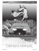
1. Remove the air dam and bumper. Retain the
fasteners for later installation.
2. Remove compatibility structures, if vehicle is so
equipped. Retain them for reinstallation if the
snowplow mount is removed from the vehicle.
3. Remove the metal sway bar brackets and retain
for reinstallation later in this procedure.
CAUTION
Read instructions before assembling.
Fasteners should be nger tight until
instructed to tighten according to the torque
chart. Use standard methods and practices
when attaching snowplow, including proper
personal protective safety equipment.
1/4-20 10
91
54
1/4-28 12
11
71
5/16-1
81
50 212
5/16-2
41
70 240
3/8-16 269 376
3/8-24 29
74
20
7/16-1442
96
06
7/16-20
9/16-12
9/16-18
5/8-11
5/8-18
3/4-10
3/4-16
7/8-9
7/8-14 47
46
69
64
49
091-8
1-12 70
49
95
1/2-13
1/2-20
11.9
13.7
24.6
27.3
43.6
26.9
53.3
93
148
49.4
69.8
77.9
106.4
120.0
8.4
9.7
17.4
19.2
30.8
35.0
49.4
55.2
75.3
85.0
M6 x 1.00
M12 x 1.75
M8 x 1.25
M14 x 2.00
M10 x 1.50
M27 x 3.00
M22 x 2.50
M30 x 3.50
M24 x 3.00
M20 x 2.5011.1
19.5
38.5
67
107
7.7
613
778
1139
1545
450
428
562
796
1117
M33 x 3.50
M36 x 4.00
2101
2701
1468
1952
325
M16 x 2.00 231167
M18 x 2.50 318222
Recommended Fastener Torque Chart
Size Size
Torque (ft-lb)
Grade
5
Grade
8
Metric Fasteners Class 8.8 and 10.9
These torque values apply to fasteners
except those noted in the instructions.
Torque (ft-lb)
Grade
5
Grade
8
Size Size
Torque (ft-lb)
Class
8.8
Class
10.9
Torque (ft-lb)
Class
8.8
Class
10.9
Inch Fasteners Grade 5 and Grade 8
NOISE
Airborne noise emission during use is below 70 dB(A)
for the snowplow operator.
VIBRATION
Operating snowplow vibration does not exceed
2.5 m/s2 to the hand‑arm or 0.5 m/s2 to the whole
body.
TORQUE CHART
Remove compatibility structures.

Lit. No. 42135, Rev. 04 5 December 15, 2017
31269‑1
4. Completely remove the sway bar fasteners and
bolt clips from the keyholes in the truck frame.
Retain the fasteners and clips for reinstallation if
the mount kit is removed from the vehicle.
5. Place a spacer inside the passenger's side of the
truck frame with the slots closest to the center
of the vehicle. Insert a 7/16" x 2‑1/2" cap screw
down through a 7/16" washer, the spacer, and the
truck frame.
6. Position the passenger‑side rear bracket so that
the cap screw goes through the appropriate hole.
On 2011–16 model year F‑250 and F‑350
installations and all F‑450 and F‑550
installations, insert an additional 7/16" washer
between the truck frame and the rear bracket.
Place the sway bar in position and align the sway
bar bracket so that the fastener is in the correct
hole. Attach a 7/16" locknut and hand tighten.
7. Insert a second 7/16" x 2‑1/2" cap screw through a
washer, the spacer, and the truck frame.
On 2011–16 model year F‑250 and F‑350
installations and all F‑450 and F‑550
installations, insert an additional 7/16" washer
between the truck frame and the rear bracket.
Insert the cap screw through the rear bracket
and sway bar bracket. Attach a 7/16" locknut and
hand tighten.
8. Insert a 1/2" x 1‑1/2" cap screw and 1/2" washer
into the truck frame and out through the front
hole in the rear bracket. Attach a 1/2" locknut and
hand tighten.
9. Position the passenger‑side mount so that the rear
hole is aligned with the rear hole in the bracket.
Insert a 1/2" x 1‑1/2" cap screw through the hole in
the mount and rear bracket, attach a 1/2" locknut,
and hand tighten.
10. Rotate the mount up against the truck frame.
Insert a 1/2" x 1‑1/2" cap screw into the rear inner
hole at the front of the mount and through the
truck frame. Attach a 1/2" washer and 1/2" locknut
on the inside of the truck frame and hand tighten.
11. Insert a 1/2" x 1‑1/2" cap screw into the front
inner hole in the passenger‑side mount. Attach a
1/2" washer and 1/2" locknut on the inside of the
truck frame and hand tighten.
12. Insert a 1/2" x 1‑1/2" cap screw and 1/2" washer
into the truck frame and out through the rear
outer hole in the mount. Attach a 1/2" washer and
locknut and hand tighten.
13. For 2008–09 model years: Insert a
1/2" x 1‑1/2" cap screw into the truck frame and
out through the front outer hole in the mount.
Attach a 1/2" locknut and hand tighten.
For 2010–16 model years: Insert a
1/2" x 1‑1/2" cap screw into the truck frame and
out through the middle outer hole in the mount.
Attach a 1/2" locknut and hand tighten.
14. Install two more cap screws through the holes in
the mount and rear bracket. Attach locknuts to
fully secure the rear bracket to the mount. Hand
tighten fasteners.
For 2010–16 models, insert
1/2" x 1-1/2" cap screw
in the middle outer hole.
For 2008–09 models, insert
1/2" x 1-1/2" cap screw
in the front outer hole.

Lit. No. 42135, Rev. 04 6 December 15, 2017
31269‑1
15. Repeat Steps 5–9 on the driver's side.
16. Rotate the mount up against the truck frame.
Insert a 1/2" x 1‑1/4" cap screw and 1/2" washer
into the truck frame and out through the rear
inner hole at the front of the mount. Attach a
1/2" locknut and hand tighten.
17. Insert a 1/2" x 1‑1/4" cap screw into the truck
frame and out through the front inner hole in
the driver‑side mount. Attach a 1/2" washer and
1/2" locknut and hand tighten.
18. Insert a 1/2" x 1‑1/2" cap screw and 1/2" washer
into the truck frame and out through the rear
outer hole in the mount. Attach a 1/2" washer and
locknut and hand tighten.
19. For 2008–09 model years: Insert a
1/2" x 1‑1/2" cap screw into the truck frame and
out through the front outer hole in the mount.
Attach a 1/2" locknut and hand tighten.
For 2010–16 model years: Insert a
1/2" x 1‑1/2" cap screw into the truck frame and
out through the middle outer hole in the mount.
Attach a 1/2" locknut and hand tighten.
20. Install two more 1/2" x 1‑1/2" cap screws through
the holes in the mount and rear bracket. Attach
1/2" locknuts to fully secure the rear bracket to the
mount. Hand tighten fasteners.
21. Install the cross bar on the rear side of the mount
tabs using four 1/2" x 1‑1/2" cap screws and
1/2" locknuts. Hand tighten fasteners.
22. Fully tighten the rear bracket fasteners according
to the torque chart.
23. Make sure the mounts are tight up against the
truck frame. Fully tighten the fasteners securing
the mount to the truck frame and rear bracket
according to the torque chart.
24. Remove the plastic bracket holding the metallic
cooling lines from the passenger's side of the
truck frame. Stack three 1/2" washers over the
fastener.
CAUTION
Diesel-equipped vehicles must use supplied
1/2" x 1‑1/4" cap screws between frame and
intercooler to prevent intercooler damage
during assembly and use.
1/
2" x 1-1/2"
Cap Scre
w
(I
nsert from
insi
de of frame.)
1/2" x 1-1/2"
Cap Screw
1/2" x 1-1/4" Cap Screw
(Insert from
inside of frame,
driver's side only.)
For 2008–09 models,
use the front outer hole.
For 2010–16 models
,
use the middle
outer hole
.
Remove bracket
and add 3 washers.

Lit. No. 42135, Rev. 04 7 December 15, 2017
31269‑1
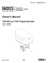
27. Check for a U-bracket distance of 30-7/16" ± 1/8".
Take a second measurement farther back on
the mounts to ensure that they are parallel. If the
U -bracket distance is not within 30-7/16" ± 1/8",
then 1/2" at washers may be used to shim one
or both mounts in the appropriate direction to
obtain the desired dimension. Tighten all fasteners
according to the torque chart after achieving the
appropriate dimensions.
28. Reattach the bumper using the original fasteners.
29. If the air dam does not clear the U-brackets, notch
it as needed.
NOTE: For 2008–10 model year vehicle applications,
install the 68210 Headlamp Extension Bracket Kit
to the headgear according to the instructions
included with the bracket kit.
NOTE: After ve to ten hours of snowplow usage,
retorque all mount assembly fasteners.
25. Reinsert the fastener into the original hole to hold
its position. Wrap the cable tie around the entire
frame and tubing behind the bracket. Do not wrap
cable tie over any other wires or tubes or go inside
the truck frame.
26. Tighten cable tie until it is snug, taking care not to
crimp tubing. Trim excess length.
Place cable tie around entire
frame and under all cables.
Tubing should
clear cap screws.
30-7/16" ± 1/8"
Center to Center

Lit. No. 42135, Rev. 04 8 December 15, 2017
31269‑1
The company reserves the right under its product improvement policy to change construction or design details and furnish equipment when
so altered without reference to illustrations or specications used. This equipment manufacturer or the vehicle manufacturer may require or
recommend optional equipment for snow removal. Do not exceed vehicle ratings with a snowplow. The company offers a limited warranty for
all snowplows and accessories. See separately printed page for this important information.
Printed in U.S.A.
/