Page is loading ...

FEBRUARY 2003
KV1500A
KV1501A
KV1502A
KV1503A
FREE tech support 24 hours a day, 7 days a week: Call 724-746-5500 or fax 724-746-0746.
Mailing address: Black Box Corporation, 1000 Park Dr., Lawrence, PA 15055-1018
World-Wide Web: www.blackbox.com • E-mail: [email protected]
© Copyright 2003. Black Box Corporation. All rights reserved.
Customer Support Information:

1
THE SERVSWITCH™ FAMILY
Welcome to the ServSwitch™ Family!
Thank you for purchasing a BLACK BOX
®
ServSwitch™ Brand KVM switch! We
appreciate your business, and we think you’ll appreciate the many ways that this
product will save you money, time, and effort.
Our ServSwitch family is all about breaking away from the traditional, expensive
model of computer management and display. You know, the one-size-fits-all-even-if-it-
doesn’t model that says, “One computer gets one dedicated monitor or user station, no
more, no less.” Why not a single user station (monitor, keyboard, and mouse) for
multiple computers—even computers of different platforms? Why not a pair of user
stations, each of which can control multiple computers? Why not many monitors or
user stations for the same computer? Why not access or display any of your computers,
anywhere in the world, with any of your user stations or monitors?
With our ServSwitch products, there’s no reason why not. We carry a broad line of
robust solutions for all these applications:
•
Do you have just two PCs and need an economical alternative to keeping two mice,
keyboards, and monitors on your desk? Or do you need to share many computers,
including a mix of IBM
®
PC, RS/6000
®
, Apple
®
Macintosh
®
, Sun Microsystems
®
,
and SGI™ types among multiple worldwide users with different access levels?
• Do you have to send video from one computer to two different local monitors? Or
do you need to send video from multiple computers to dozens of remote monitors?
•
Does your switch have to sit solidly on a worktable and use regular everyday cables?
Or does it have to be mounted in an equipment rack, use convenient many-to-one
cables, and have a rackmounted user station that folds and slides into 1U of space?
No matter how large or small your setup is, no matter how simple or how complex,
we’re confident we have a ServSwitch system that’s just right for you. The ServSwitch™
family from Black Box—the one-stop answer for all your video and KVM switching and
extension needs!
*
This manual will tell you all about your new ServSwitch™ Summit, including how to
install, operate, and troubleshoot it. For an introduction to the Summit, see Chapter 3.
The Summit product codes covered in this manual are:
KV1500A KV1501A KV1502A KV1503A
This manual also includes information about the ServSwitch™ Summit’s User-Station
and Computer-Interface Modules, some of which have their own manuals or
installation guides:
KV1510A KV1515A KV1516A KV1517A KV1518A KV1519A

2
SERVSWITCH™ SUMMIT
FEDERAL COMMUNICATIONS COMMISSION AND INDUSTRY CANADA
RADIO-FREQUENCY INTERFERENCE STATEMENTS
This equipment generates, uses, and can radiate radio-frequency energy, and if not
installed and used properly, that is, in strict accordance with the manufacturer’s
instructions, may cause interference to radio communication. It has been tested
and found to comply with the limits for a Class A computing device in accordance
with the specifications in Subpart B of Part 15 of FCC rules, which are designed to
provide reasonable protection against such interference when the equipment is
operated in a commercial environment. Operation of this equipment in a
residential area is likely to cause interference, in which case the user at his own
expense will be required to take whatever measures may be necessary to correct the
interference.
Changes or modifications not expressly approved by the party responsible for
compliance could void the user’s authority to operate the equipment.
This digital apparatus does not exceed the Class A limits for radio noise emission from
digital apparatus set out in the Radio Interference Regulation of Industry Canada.
Le présent appareil numérique n’émet pas de bruits radioélectriques dépassant les limites
applicables aux appareils numériques de la classe A prescrites dans le Règlement sur le
brouillage radioélectrique publié par Industrie Canada.
TRADEMARKS USED IN THIS MANUAL
BLACK BOX and the logo are registered trademarks, and ServSwitch and
ServSwitch Summit are trademarks, of Black Box Corporation.
Apple and Macintosh are registered trademarks of Apple Computer, Inc.
Lexan is a registered trademark of GE.
IBM, PC/AT, PS/2, and RS/6000 are registered trademarks of International
Business Machines Corporation.
Windows is a registered trademark or trademark of Microsoft Corporation in the
United States and/or other countries.
Sun and Sun Microsystems are registered trademarks of Sun Microsystems, Inc. in
the United States and other countries.
UL is a registered trademark of Underwriters Laboratories Incorporated.
Any other trademarks mentioned in this manual are acknowledged to be the property of the
trademark owners.

3
EU DECLARATION OF CONFORMITY, VCCI STATEMENT
EUROPEAN UNION DECLARATION OF CONFORMITY
This equipment has been tested and found to comply with the limits for a class A
computing device in accordance with the specifications in the European standard
EN55022. These limits are designed to provide reasonable protection against
harmful interference. This equipment generates, uses and can radiate radio-
frequency energy, and if not installed and used in accordance with the
instructions, might cause harmful interference to radio or television reception.
However, there is no guarantee that harmful interference will not occur in a
particular installation. If this equipment does cause interference to radio or
television reception, which can be determined by turning the equipment on and
off, you can correct the interference with one or more of the following measures:
(a) Reorient or relocate the receiving antenna.
(b) Increase the separation between the equipment and the receiver.
(c) Connect the equipment to an outlet on a circuit different from that to which
the receiver is connected.
(d) Consult the supplier or an experienced radio/TV technician for help.
Shielded cables must be used to connect other compliant devices to this
equipment in order to maintain compliance with radio-frequency-energy emission
regulations and ensure a suitably high level of immunity to electromagnetic
disturbances.

4
SERVSWITCH™ SUMMIT
NORMAS OFICIALES MEXICANAS (NOM)
ELECTRICAL SAFETY STATEMENT
INSTRUCCIONES DE SEGURIDAD
1. Todas las instrucciones de seguridad y operación deberán ser leídas antes de
que el aparato eléctrico sea operado.
2. Las instrucciones de seguridad y operación deberán ser guardadas para
referencia futura.
3. Todas las advertencias en el aparato eléctrico y en sus instrucciones de
operación deben ser respetadas.
4. Todas las instrucciones de operación y uso deben ser seguidas.
5. El aparato eléctrico no deberá ser usado cerca del agua—por ejemplo, cerca
de la tina de baño, lavabo, sótano mojado o cerca de una alberca, etc.
6. El aparato eléctrico debe ser usado únicamente con carritos o pedestales que
sean recomendados por el fabricante.
7. El aparato eléctrico debe ser montado a la pared o al techo sólo como sea
recomendado por el fabricante.
8. Servicio—El usuario no debe intentar dar servicio al equipo eléctrico más allá
a lo descrito en las instrucciones de operación. Todo otro servicio deberá ser
referido a personal de servicio calificado.
9. El aparato eléctrico debe ser situado de tal manera que su posición no
interfiera su uso. La colocación del aparato eléctrico sobre una cama, sofá,
alfombra o superficie similar puede bloquea la ventilación, no se debe colocar
en libreros o gabinetes que impidan el flujo de aire por los orificios de
ventilación.
10. El equipo eléctrico deber ser situado fuera del alcance de fuentes de calor
como radiadores, registros de calor, estufas u otros aparatos (incluyendo
amplificadores) que producen calor.
11. El aparato eléctrico deberá ser connectado a una fuente de poder sólo del
tipo descrito en el instructivo de operación, o como se indique en el aparato.

5
NOM STATEMENT
12. Precaución debe ser tomada de tal manera que la tierra fisica y la polarización
del equipo no sea eliminada.
13. Los cables de la fuente de poder deben ser guiados de tal manera que no
sean pisados ni pellizcados por objetos colocados sobre o contra ellos,
poniendo particular atención a los contactos y receptáculos donde salen del
aparato.
14. El equipo eléctrico debe ser limpiado únicamente de acuerdo a las
recomendaciones del fabricante.
15. En caso de existir, una antena externa deberá ser localizada lejos de las lineas
de energia.
16. El cable de corriente deberá ser desconectado del cuando el equipo no sea
usado por un largo periodo de tiempo.
17. Cuidado debe ser tomado de tal manera que objectos liquidos no sean
derramados sobre la cubierta u orificios de ventilación.
18. Servicio por personal calificado deberá ser provisto cuando:
A: El cable de poder o el contacto ha sido dañado; u
B: Objectos han caído o líquido ha sido derramado dentro del aparato; o
C: El aparato ha sido expuesto a la lluvia; o
D: El aparato parece no operar normalmente o muestra un cambio en su
desempeño; o
E: El aparato ha sido tirado o su cubierta ha sido dañada.

6
SERVSWITCH™ SUMMIT
Contents
Chapter Page
1. Quick Install Guide .................................................................................... 8
1.1 Basic Installation ................................................................................. 9
1.2 Initial Administrative Testing ........................................................... 10
2. Specifications ........................................................................................... 12
3. Introduction ............................................................................................. 17
3.1 Overview ............................................................................................ 17
3.2 Features and Benefits ....................................................................... 18
3.3 Complete Packages ........................................................................... 19
3.4 The Summit Illustrated .................................................................... 20
4. Installation and Initial Configuration .................................................... 21
4.1 Using the OSUI for Initial Configuration ....................................... 21
4.2 Installing a Summit System with a Single Base Unit ....................... 22
4.3 Installing a Cascaded Summit System .............................................. 27
5. User Functions ......................................................................................... 32
5.1 Login .................................................................................................. 32
5.2 Selecting a Computer ....................................................................... 33
5.3 Customizing How the USM Operates for You ................................ 37
5.4 Keyboard-Controlled OSUI Functions ............................................ 41
5.5 The Information Menu .................................................................... 42
6. Administrator Functions ......................................................................... 43
6.1 The Administration Menu ................................................................ 43
6.2 System Configuration ....................................................................... 44
6.3 User Configuration ........................................................................... 47
6.4 Channel Configuration .................................................................... 49
6.5 User Station Profile ........................................................................... 51
6.6 Refresh Configurations ..................................................................... 52
6.7 Autoscanning and Autoskipping ...................................................... 52
6.8 Resetting a Base Unit to Its Factory Defaults .................................. 52

7
TABLE OF CONTENTS
Chapter Page
7. Troubleshooting ...................................................................................... 53
7.1 Calling Black Box .............................................................................. 53
7.2 Shipping and Packaging ................................................................... 53
Appendix A: Group Settings (Access Rights) ............................................... 54
Appendix B: USM Direct Mode ..................................................................... 55
Appendix C: Using a KV1519A to Access a Local CPU ................................ 56
Appendix D: Updating the Summit’s Firmware ........................................... 59
Appendix E: Surface/Rackmounting ............................................................ 63
Appendix F: CAT5 Cable Guidelines ............................................................ 68
Appendix G: Using the RS-232 Serial CIM: (KV1518A) ............................... 69
G.1 Introduction to the KV1518A ........................................................... 69
G.2 Installing the KV1518A ..................................................................... 70
G.3 Operating the KV1518A ................................................................... 71
G.3.1 Screen Layout .......................................................................... 71
G.3.2 On-Line Mode ......................................................................... 73
G.3.3 Buffer Edit Mode .................................................................... 73
G.4 Configuring the KV1518A ................................................................ 76
G.5 Troubleshooting the KV1518A ........................................................ 78
Appendix H: Emulating Sun Keys with a PS/2 Keyboard ............................ 79

8
SERVSWITCH™ SUMMIT
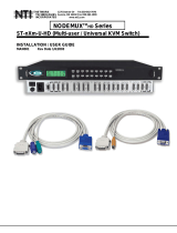
1. Quick Install Guide
Figure 1-1. The elements of a ServSwitch Summit system.
Numbers refer to basic-
installation steps on
the facing page

9
CHAPTER 1: Quick Install Guide
1.1 Basic Installation
CAUTION!
The Summit and all devices you want to attach to it must be unplugged
and powered OFF prior to installation.
To install a ServSwitch Summit system with a single Base Unit, take the following
steps, referring to Figure 1-1 on the facing page. (For cascaded systems with two or
more Base Units, see Chapter 4. For rackmounting instructions, see Appendix E.)
1. Plug the Base Unit’s included power cord into the power inlet on the rear of
the Base Unit.
2. Connect one end of a Category 5 UTP cable to RJ-45 user port # 1 on the rear
of the Base Unit. You can use one of the Summit’s included CAT5 cables for
this purpose if you want to.
3. Connect the other end of the cable to the RJ-45 CAT5 port on the rear of a
User Station Module (“USM”).
4. Plug the USM’s included power cord into the power inlet on the rear of the
USM. Power ON the USM.
5. Connect an IBM
®
PS/2
®
type keyboard, PS/2 type mouse, and VGA monitor
to the USM. Plug in and power ON the monitor.
Repeat steps 2 through 5 for all other keyboard/monitor/mouse user stations you
want to attach.
6. Connect one end of a Category 5 UTP cable to RJ-45 channel port # 1 on the
rear of the Base Unit. Again, you can use one of the Summit’s CAT5 cables.
7. Connect the other end of the cable to the RJ-45 port on a Computer Interface
Module (“CIM”).
8.
Plug the CIM’s keyboard, video,
and mouse cords into a computer CPU’s
keyboard, video, and mouse ports.
9. Power ON the CPU.
Repeat steps 6 through 9 for all other CPUs you want to attach.

10
SERVSWITCH™ SUMMIT
1.2 Initial Administrative Testing
To verify that an attached computer can be viewed and controlled through the
ServSwitch Summit system, take these steps:
1. When you first power ON the ServSwitch Summit Base Unit, an attached
USM, and the USM’s attached monitor, a Login Menu will be displayed on
the monitor, as shown in Figure 1-2. Type admin (all lowercase) in the User
Name field and press [Enter]. Type blackbox (all lowercase) in the
Password field and press [Enter].
NOTE
The factory-default user names are user01 through up to user15
(depending on the model of the Base Unit) for regular users and admin
for the admin user. User names are not case-sensitive. By default, a
password is required only for the admin user, and that password is
blackbox. Passwords are case-sensitive.
Figure 1-2. The Login Menu for a KV1502A.
2. The monitor will display an On-Screen User Interface (OSUI) Selection
Menu (shown in Figure 1-3) with the channel of the connected CPU
displayed in green. (It will have no default name—the Name field will be
blank.)
3. Use the up- and down-arrow keys on the user station’s keyboard to move the
highlight to the green computer channel and press [Enter].
4. Normal computer access and operation indicates a successful connection.
A video-gain adjustment is available to focus the video image, which can be
especially useful if you’re using an LCD flat-panel monitor. To make this
adjustment, activate the OSUI (if you haven’t done so already) by rapidly pressing
the keyboard’s [Scroll Lock] key twice. Use the “+” and “-” (plus- and minus-sign)
keys on the keyboard’s numeric keypad to adjust the video image until it appears
to be in focus.
Please Login ServSwitch Summit
Device ID: Summit 8x32
User Port: 1
User Name:
Password:
Enter Name and Password

11
CHAPTER 1: Quick Install Guide
For more information about installing, configuring, operating, and
troubleshooting a Summit system, read the rest of this manual.
Figure 1-3. The Selection Menu for a KV1502A (shown after a
hypothetical basic system configuration is finished).
Selection Menu
Summit 8x32 Page 1/8
No Ch.ID Name Scn
-- -------- ------------ ---
1 01 03
2 02 NT40-Mail 03
3 03 Wins95_Bob 03
4 04 Wins98_Jack 03
5 05 Wins98_Jana 03
6 06 NT40-Fax 03
7 07 Wins95_Paul 03
8 08 Wins98_Sher 03
-- -------- ------------ ---
ScrlLock | Scan | Skip NCSL
3 03 Wins95_Bob 03
Page FKey Ent Esc

12
SERVSWITCH™ SUMMIT
2. Specifications
Cable Required: Between Base Units, USMs, and CIMs: Four-pair (eight-
wire) Category 5 solid-core unshielded twisted-pair
(UTP) pinned and paired according to TIA-568B
Compliance: EMI/RFI radiation: CE; FCC Part 15 Subpart B Class A,
IC Class/classe A;
EMI/RFI immunity: CE;
Electrical safety: UL
®
, cUL
Standards: VGA, SVGA, XGA, or XGA-2 video;
Interfaces: On all units: Proprietary composite of supported
keyboard, video, mouse, and (when any KV1518As are
involved) serial signals;
On the Base Unit:
Serial: EIA/TIA RS-232 pinned to TIA-574, DCE (for
firmware updates only);
Expansion: Wide SCSI-2 (nonfunctional);
On the USM:
Video: VGA;
Keyboard and mouse: IBM PS/2 or Sun compatible;
Serial: EIA/TIA RS-232 pinned to TIA-574, DCE (for
firmware updates only);
On all CIMs except KV1518A: To computers’ keyboard
and mouse ports:
KV1515A or KV1519A: IBM PS/2 compatible;
KV1516A: Sun compatible;
KV1517A: USB;
On the KV1518A CIM: EIA/TIA RS-232, DTE, to CPUs’
RS-232 serial ports
Resolution and
Refresh Rate: With premium CAT5 cable: Up to 1280 x 1024 at up to
75 Hz
Serial
Characteristics: Base Units and USMs: Proprietary (communicate with
firmware-upgrade program only);

13
CHAPTER 2: Specifications
Serial (continued): KV1518A: Supports X-ON/X-OFF flow control to
attached device; other characteristics are user-
selectable: 2400, 4800, 9600, or 19,200 bps; 7 or 8 data
bits; even, odd, or no parity; and 1 or 2 stop bits (if
7 data bits has been selected, there must be 2 stop bits)
Maximum
Distance: End to end, from CPUs to user stations: 500 ft. (152 m)
User Controls: On-Screen User Interface (OSUI);
Keyboard commands;
Rear-mounted ON/OFF rocker switch on each Base Unit
and USM
Indicators: On Base Units: All front-mounted: (1) Unit-power LED,
(1) port-power LED for each user and channel port;
On USMs: (1) Front-mounted unit-power LED
On CIMs: (1) Power/activity LED; near 6-pin mini-DIN
connector on KV1518A, near RJ-45 on other models
Connectors: On Base Units: All rear-mounted:
RJ-45 female to USMs:
KV1500A: (2);
KV1501A: (4);
KV1502A: (8);
KV1503A: (16);
RJ-45 female to CIMs:
KV1500A and KV1501A: (42);
KV1502A: (32);
KV1503A: (64);
(2) Internal-style micro D68 expansion ports (reserved
for future use);
(1) DB9 female RS-232 serial admin port for firmware
upgrades;
(1) IEC 320 male power inlet;
On USM (KV1510A): All-rear-mounted:
(1) RJ-45 female to Base Unit;
(1) HD15 female to monitor;
(2) 6-pin mini-DIN female: (1) to PS/2 keyboard,
(1) to PS/2 mouse;
(1) 8-pin mini-DIN female to Sun keyboard and mouse;
(1) DB9 female RS-232 serial admin port for firmware
upgrades;
(1) IEC 320 male power inlet;

14
SERVSWITCH™ SUMMIT
Connectors
(continued): On all CIMs:
(1) HD15 male to CPU’s video port;
(1) RJ-45 female to Base Unit;
On KV1515A and KV1519A:
(2) 6-pin mini-DIN male: (1) to CPU’s PS/2 keyboard
port, (1) to CPU’s PS/2 mouse port;
On KV1519A:
(1) RJ-45 female to USM;
On KV1516A:
(1) 8-pin mini-DIN male to Sun keyboard/mouse port;
On KV1517A:
(1) USB Type A male to USB keyboard/mouse port;
On KV1518A:
(1) DB25 female to RS-232 serial port (DTE—can’t be
directly connected)
Maximum
Altitude: Operating: 10,000 ft. (3048 m);
Storage: 40,000 ft. (12,192 m)
Temperature
Tolerance: Operating: 32 to 104˚F (0 to 40˚C);
Storage: 32 to 122˚F (0 to 50˚C)
Humidity
Tolerance: Operating: 20 to 85% noncondensing;
Storage:
KV1518A: 20 to 90% noncondensing;
All other Summit devices: 10 to 90% noncondensing
Vibration
Tolerance: Passes testing at 5-55-5 Hz, 0.38 mm, 1 minute per cycle;
30 minutes for each axis (X, Y, Z)
Enclosure: Base Units and USM: Steel and Lexan
®
;
CIMs: Injection-molded plastic
MTBF (calculated): KV1500A and KV1501A: 117,000 hours;
KV1502A: 853,000 hours;
KV1503A: 131,000 hours;
KV1510A: 813,000 hours;
KV1515A: 8,844,000 hours;
KV1516A: 2,399,000 hours;

15
CHAPTER 2: Specifications
MTBF (continued): KV1517A: 2,308,000 hours;
KV1518A: 1,691,000 hours;
KV1519A: 879,000 hours
Power: All Base Units and USM: From utility-power (mains)
outlet, through detachable power cord and IEC 320
inlet, to internal transformer:
Input: 100 to 240 VAC at 47 to 63 Hz, up to 600 mA;
Average consumption at 110 VAC:
KV1500A, KV1510A: 17.6 watts;
KV1501A: 19.8 watts;
KV1502A: 25.3 watts;
KV1503A: 34 watts;
KV1518A: From utility-power (mains) outlet, through
detachable power cord and IEC 320 inlet, to external
transformer:
Input: 100 to 240 VAC at 47 to 63 Hz and up to
500 mA;
Output: 5 VDC at up to 300 mA;
All other CIMs: 5 VDC from attached keyboard port:
KV1515A and KV1516A: At ~120 mA;
KV1517A: At ~150 mA;
KV1519A: At ~200 mA
Size: KV1500A and KV1501A: 1.75"H x 17.2"W x 10.4"D (4.4 x
43.7 x 26.4 cm);
KV1502A: 1.75"H x 16.7"W x 11.3"D (4.4 x 42.4 x 28.7 cm);
KV1503A: 3.5"H x 17.25"W x 10.75"D (8.9 x 43.8 x
27.3 cm);
KV1510A: 1.75"H x 11.4"W x 10.1"D (4.4 x 29 x 25.7 cm);
KV1515A and KV1516A: 0.6"H x 1.3"W x 3"D (1.5 x 3.3 x
7.6 cm), plus a 4" (10.2-cm) cord from the CIM to its
HD15 connector (which is 1.9" [4.8 cm] long) and a
13" (33-cm) cord from its HD15 connector to its
keyboard/mouse connector(s);
KV1517A: 0.6"H x 1.3"W x 3"D (1.5 x 3.3 x 7.6 cm), plus
a 4" (10.2-cm) cord from the CIM to its HD15
connector (which is 1.9" [4.8 cm] long) and a 14"
(35.6-cm) cord from its HD15 connector to the end of
its USB Type A connector;
KV1518A: 0.9"H x 4.3"W x 3.6"D (2.3 x 10.9 x 9.1 cm);

16
SERVSWITCH™ SUMMIT
Size (continued): KV1519A: 1"H x 2.4"W x 3.5"D (2.5 x 6.1 x 8.9 cm), plus
a 14" (35.6-cm) cord from the CIM to its HD15
connector and two 18" (45.7-cm) cords from the CIM
to its 6-pin mini-DIN connectors
Weight: KV1500A: 8.4 lb. (3.8 kg);
KV1501A: 8.5 lb. (3.9 kg);
KV1502A: 7.4 lb. (3.4 kg);
KV1503A: 12 lb. (5.4 kg);
KV1510A: 4.3 lb. (2 kg);
KV1515A and KV1517A: 2.6 oz. (74 g);
KV1516A: 2.1 oz. (60 g);
KV1518A: 0.7 lb. (0.3 kg);
KV1519A: 0.4 lb. (0.2 kg)

17
CHAPTER 3: Introduction
3. Introduction
3.1 Overview
The ServSwitch™ Summit is designed to perform heavy-duty multiple-user-to-
many-computer keyboard/video/mouse (KVM) matrix switching without
burdening you with big, confusing hydra-headed cables. Instead, the Summit uses
standard Category 5 unshielded twisted-pair (UTP) cabling, like the type that’s
already installed at many sites. It can connect users with computers across as much
as 500 ft. (152 m) of such cabling.
ServSwitch Summit systems consist of three components: Base Units, which do
the matrix switching; Computer-Interface Modules (CIMs) connected to each
computer; and User-Station Modules (USMs) connected to each set of user-station
equipment.
There are a number of Base Unit models that support different numbers of
directly attached users and computer CPUs:
• Product code KV1500A supports 2 users and 42 CPUs;
• KV1501A supports 4 users and 42 CPUs;
• KV1502A supports 8 users and 32 CPUs;
• KV1503A supports 16 users and 64 CPUs.
There are also several different CIMs for different types of computers (all must
output VGA video):
• KV1515A and KV1519A support CPUs with IBM
®
PS/2
®
type keyboard and
mouse ports; KV1519A has an extra RJ-45 port to support a “local CPU”
installed between a USM and a Base Unit (see Appendix C).
• KV1516A supports CPUs with Sun
®
type keyboard and mouse ports;
• KV1517A supports CPUs with USB keyboard and mouse ports;
• KV1518A supports CPUs connected through their RS-232 serial ports;
There is one universal USM (KV1510A) that supports either a PS/2 or Sun type
keyboard and mouse. (We recommend that you use a Sun keyboard if there are
any Sun CPUs in your system; if you must use a PS/2 keyboard to control Sun
CPUs, see Appendix H for how to produce a Sun keyboard’s special characters.) If
you want to connect one user station to one CPU across a long stretch of CAT5 or
higher cable, you can run such a cable between a “direct mode” USM and a CIM
(see Appendix B).

18
SERVSWITCH™ SUMMIT
3.2 Features and Benefits
Some useful features of the Summit:
• Base Unit available in models to which you can directly attach 2 users and
42 computers (KV1500A), 4 users and 42 computers (KV1501A), 8 users and
32 computers (KV1502A), or 16 users and 64 computers (KV1503A).
• Cascade Matrix Switching Units to expand to up to 2048 servers.
• Base Unit chassis can be mounted in 2U (KV1503A) or 1U (all other models)
of vertical space in a 19" rack using the included brackets.
• Connect users and computers up to 500 feet (152 m) apart.
• Simple plug-and-play, auto-configure installation.
• Hot-swappable components have no impact on server operation.
• Platform-specific Computer-Interface Modules (CIMs) for computer CPUs
with PS/2 (KV1515A regular or KV1519A for local PC), Sun (KV1516A), or
USB (KV1517A) keyboard and mouse ports, or with RS-232 serial (KV1518A)
ports.
• KV1510A User-Station Module (USM) supports both PS/2 and Sun keyboards
and mice.
• The USM can be set loosely on a flat surface, mounted on a flat surface with
the included mounting hardware, or mounted in a rack with the RMKSMU kit
(available separately; see Appendix E).
• Supports high-resolution video, up to 1280 x 1024 at up to 75 Hz.
• Powerful, intuitive on-screen user interface for simple operation.
• Up to 127 customized user profiles.
• Flexible, multi-level security for authorized computer access.
• Three system-operation modes—private, public, and share.
• Flash-upgradable firmware.

19
CHAPTER 3: Introduction
3.3 Complete Packages
The ServSwitch Summit Base Units come with:
• (1) Base Unit;
• (2) 20-ft. (6.1-m) CAT5 test cables (replacement product code
EYN737MS-0020);
• (1) Pair of rackmount brackets and associated screws (replacement product
code RMKSM2 for KV1503A, RMKSM1 for all other models);
• (1) 10-ft. (3-m) DB9 male-to-female serial administration cable (replacement
product code BC00230);
• (1) 6-ft. (1.8-m) AC power cord; and
• This manual.
The ServSwitch Summit USM comes with:
• (1) User-Station Module;
• (1) Surface-mount bracket and associated screws (replacement product code
RMKSM0);
• (1) 6-ft. (1.8-m) AC power cord;
• (1) 6-ft. (1.8-m) AC power-extension cord for the attached monitor; and
• An installation and operation guide.
The ServSwitch Summit serial CIM (KV1518A) comes with:
• (1) Computer-Interface Module;
• (1) AC power supply with a 6-ft. (1.8-m) input cord and a 4-ft. (1.2-m) output
cord;
• An installation and operation guide.
The other CIMs don’t ship with anything besides the Computer-Interface Modules
themselves and an installation guide.
If you didn’t receive everything, or if anything arrived damaged, contact Black
Box right away.
/